Advertisement
Quick Links
Applied Machines: C554e/C454e/C364e/C284e/C224e/C554/C454/C364/C284/C224/C368/C308/554e/454e/364e/
284e/224e/367/287/227
COLOR MFP: 55 ppm/45 ppm/36 ppm/30 ppm/28 ppm/22 ppm
MFP: 55 ppm/45 ppm/36 ppm/28 ppm/22 ppm
Product Code: A5AY/A5C0/A5C1/A5C2/A5C4/A2XK/A4FJ/A161/A4FK/A4FM/A7PU/A7PY/A61D/A61E/A61F/A61G/
A61H/A789/A7AH/A7AK
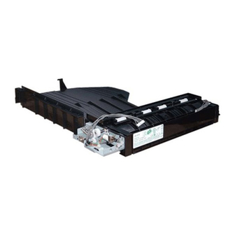
1. Accessory parts
No.
Name
1. Upper tray
2. Sensor unit
3. Film
4. Hook
*1
5. Regulating
*1
plate
6. Screw A
(3 x 8 mm)
7. Screw B
(3 x 10 mm)
8. Screw C
*2
(3 x 16 mm)
9. Screw D
*1
(4 x 8 mm)
10. Installation
manual
JS-506
INSTALLATION MANUAL
Shape
Q'ty
1
1
1
1
1
1
3
2
1
1 set
Job Separator
*1
This part is used only when the Job Separator
is installed to 367/287/227.
*2
This part is used only when the Job Separator
is installed to C554e/C454e/C364e/C284e/
C224e/C554/C454/C364/C284/C224/C368/
C308/554e/454e/364e/284e/224e.
Keep this bag away from babies and
children. Do not use in cribs, beds,
carriages, or playpens.
The thin film may cling to nose and
mouth and prevent breathing. This bag is
not a toy.
Note:
• This manual provides the illustrations of the
accessory parts and machine that may be
slightly different in shape from yours. In that
case, instead of the illustrations, use the
appearance of your machine to follow the
installation procedure. This does not cause any
significant change or problem with the proce-
dure.
• If none of the later steps instruct you to use the
parts including screw and cover that you
removed following the instructions described in
this manual, discard them.
E-1
A2YV-9551-00
Advertisement

Related Manuals for Konica Minolta JS-506


Summary of Contents for Konica Minolta JS-506
- Page 1 JS-506 Job Separator INSTALLATION MANUAL Applied Machines: C554e/C454e/C364e/C284e/C224e/C554/C454/C364/C284/C224/C368/C308/554e/454e/364e/ 284e/224e/367/287/227 COLOR MFP: 55 ppm/45 ppm/36 ppm/30 ppm/28 ppm/22 ppm MFP: 55 ppm/45 ppm/36 ppm/28 ppm/22 ppm Product Code: A5AY/A5C0/A5C1/A5C2/A5C4/A2XK/A4FJ/A161/A4FK/A4FM/A7PU/A7PY/A61D/A61E/A61F/A61G/ A61H/A789/A7AH/A7AK 1. Accessory parts This part is used only when the Job Separator is installed to 367/287/227.
-
Page 2: Installation Procedures
2. Installation procedures Note: When installing this option to C554e/C454e/C554/ C454/554e/454e, the following steps (3) to (9) are <C554e/C454e/C364e/C284e/C224e/C554/C454/ performed only if the optional Output Tray OT-506 C364/C284/C224/C368/C308/554e/454e/364e/ is installed. 284e/224e> (3) Check whether the output tray has the snap-fit Follow the installation procedures starting on page hook illustrated below or not. - Page 3 (6) Remove the output tray from the main unit. (10) Remove the cover from the main unit as shown in the illustration. (Two screws) < With the snap-fit hook > <C554e/C454e/C364e/C284e/C224e/C554/C454/ C364/C284/C224/554e/454e/364e/284e/224e> < Without the snap-fit hook > <C368/C308> (7) Reattach the upper left cover removed in step (5) to the main unit.
- Page 4 (12) Remove the cover from the main unit as shown (15) Attach the supplied sensor unit to the main unit in the illustration. (One screw) by fitting the two tabs into the holes. (13) Remove the knockout from the cover removed in step (12) with nippers.
- Page 5 b) Connect the sensor unit’s connector to the con- b) Connect the sensor unit connector to the con- nector described in step a). nector as shown in the illustration. Connector c) Route the harness through the wire saddles A, c) Route the sensor unit harness through the wire B, and the edge cover.
- Page 6 (19) Install the supplied upper tray into the main unit (21) Reattach the cover removed in step (10). (Two by fitting the tab into the hole. screws removed in step (10)) (22) Attach the job separator by fitting the three tabs Note: into the holes.
- Page 7 <367/287/227> (25) Plug in the two connectors of the job separator. Fit the head of the cable tie into the mounting (1) Turn OFF the power switch and unplug the hole on the main unit. power cord from the power outlet. (2) Remove protective tape and protective materials and take out accessory parts.
- Page 8 (4) Remove the guide from the main unit. (8) Remove the paper backing from the supplied film and attach it to the main unit as shown in the illustration. Note: • Alignment in vertical direction: Align the lower edge of the film with the surface of the cover in the exit section.
- Page 9 (11) Conduct the following procedure to connect the (12) Install the supplied upper tray into the main unit sensor unit's connector to the main unit. by fitting the tab into the hole. Note: a) If present, disconnect the relay connector from Fit the two protrusions on the upper tray into the the sensor unit connector.
- Page 10 (14) Reattach the cover removed in step (5). (One (17) Install the supplied hook into the job separator screw removed in step (5)) according to the following procedure. a) Press the hook into the job separator. (15) Mount the supplied regulating plate to the machine at the position shown in the illustra- b) Secure the hook by turning it in the direction tion.
- Page 11 (19) Secure the job separator with one supplied screw D. (20) Remove the cover shown in the illustration from the back of the main unit. (One screw) (21) Plug in the two connectors of the job separator. Fit the head of the cable tie into the mounting hole on the main unit.