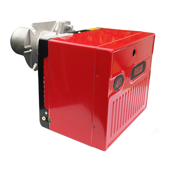
Riello 40 GS10 Installation, Use And Maintenance Instructions
Forced draught gas burner
Hide thumbs
Also See for 40 GS10:
- Installation, use and maintenance instructions (36 pages) ,
- Installation, use and maintenance instructions (36 pages) ,
- Installation, use and maintenance instructions (32 pages)
Summary of Contents for Riello 40 GS10
- Page 1 Installation, use and maintenance instructions Forced draught gas burner One - stage operation CODE MODEL TYPE 3755489 RIELLO 40 GS10 554 T85 2903159 (2) - 07/2022...
-
Page 3: Table Of Contents
INDEX BURNER DESCRIPTION ... WORKING ..... . . Burner equipment ....4.1 Combustion adjustment. -
Page 4: Technical Data
TECHNICAL DATA 2.1 TECHNICAL DATA TYPE 554T85 Thermal power 42 – 116 kW 36,000 – 100,000 kcal/h Net heat val3ue: 8 – 12 kWh/Nm 7,000 – 10,340 kcal/Nm Natural gas (Family 2) Pressure: min. 16 mbar max. 100 mbar ± Electrical supply Single phase, 100 V 50/60 Hz... -
Page 5: Installation
TEST BOILER The working field has been defined according to EN 676 standard. COMMERCIAL BOILERS The burner-boiler matching is assured if the boiler conforms to EN 303 and the combustion chamber dimen- sions are similar to those shown in the diagram EN 676. For applications where the boiler does not conform to EN 303, or where the combustion chamber is much smaller than the dimensions given in EN 676, please con- sult the manufacturers. -
Page 6: Probe-Electrode Positioning
3.2 PROBE - ELECTRODE POSITIONING Ignition electrode Ionization probe Diffuser Probe Electrode D5104 – 3 WARNING 3.3 GAS FEEDING LINE D5949 1 – Gas supply pipe 6 – Gas pressure switch 2 – Manual cock 7 – Safety valve 3 – Filter 8 –... -
Page 7: Electrical Wiring
ELECTRICAL WIRING KEY TO LAY-OUT – Capacitor CN1 – Connector SO – Electrode – Terminal strip MV – Motor – Min. air pressure switch – Min. gas pressure svitch Control box – Ionisation probe RMG 88..– Lock-out signal T6A – Fuse Ignition transformer –... -
Page 8: Fixing The Electrical Wiring
3.5 FIXING THE ELECTRICAL WIRING All the electrical wires, which are to be connected to the terminal strip (7, fig. 1, page 1) should pass through the cable grommet (4, fig. 1). All the electrical wires, which are to be connected into the terminal strip must be gripped in the cable clamps (3, fig. -
Page 9: Air Damper Setting
4.3 AIR DAMPER SETTING The regulation of the air-rate is made by adjusting the air damper (1), after loosing the screws (2). When the optimal regulation is reached, screw tight the screws (2). 4.4 COMBUSTION CHECK D5231 It is advisable to not exceed 10% of CO (natural gas) , in order to avoid the risk that small changes of the adjustments due, for instance, at draught variation, may cause combustion with insufficient air and consequently formation of CO. -
Page 10: Start-Up Cycle Diagnostics
4.6 START-UP CYCLE DIAGNOSTICS During start-up, indication is according to the following table: COLOUR CODE TABLE Sequences Colour code Pre-purging Firing phase Operation, flame ok Operating with weak flame signal Electrical supply lower than ~ 170V Lockout Extraneous light Key to layout: Yellow Green 3159... - Page 11 SAFETY TEST - WITH GAS BALL VALVE CLOSED It is fundamental to ensure the correct execution of the electrical connections between the gas solenoid valves and the burner to perform safely the commissioning. For this purpose, after checking that the connections have been carried out in accordance with the burner's elec- trical diagrams, an ignition cycle with closed gas ball valve -dry test- must be performed.
-
Page 12: Resetting The Control Box And Using
4.7 RESETTING THE CONTROL BOX AND USING DIAGNOSTICS The control box features a diagnostics function through which any causes of malfunctioning are easily identified (indicator: RED LED). To use this function, you must wait at least 10 seconds once it has entered the safety condition (lockout), and then press the reset button. - Page 13 The sequence of pulses issued by the control box identifies the possible types of malfunction, which are listed in the table below. Signal Problem Possible cause Recommended remedy 2 blinks Once the pre-purg- The operation solenoid lets little gas Increase ing phase and safety through time have passed,...
- Page 14 Signal Problem Possible cause Recommended remedy 7 blinks The burner goes into The operation solenoid lets little gas Increase lockout immediately through following the appear- Ionisation probe incorrectly adjusted Adjust ance of the flame Insufficient ionisation (less than 5 A) Check probe position Earth probe Withdraw or replace cable...
- Page 15 Signal Problem Possible cause Recommended remedy No blink Ignition with pulsa- Poorly adjusted head Adjust tions Ignition electrode incorrectly adjusted Adjust Incorrectly adjusted fan air damper: too Adjust much air Output during ignition phase is too high Reduce The burner does not Remote control device TR fails to close Adjust or replace move into the 2nd...
-
Page 16: Maintenance
MAINTENANCE Disconnect the electric supply to the burner by switching off the main power switch and close the gas shut-off valve before maintaining or checking the system. The burner requires scheduled maintenance that must be carried out by qualified personnel and in compliance with local legislation. - Page 20 RIELLO S.p.A. I-37045 Legnago (VR) Tel.: +39.0442.630111 http:// www.riello.it http:// www.riello.com Subject to modifications...


