Table of Contents

Related Manuals for TCS SZ1025b


Summary of Contents for TCS SZ1025b
- Page 1 PRODUCT MANUAL SZ1025b The SZ1025b is a microprocessor-based controller designed for VAV terminal unit applications. VAV Box Controller v0717.2 2800 Laura Lane Madison, WI 53562 | 800.836.9044 Fax: 608.836.9044 | www.tcsbasys.com...
-
Page 2: Table Of Contents
TABLE OF CONTENTS Table of Contents Manual Key . . . . . . . . . . . . . . . . . . . . . . . . . . . . . . . . . . . . . . . . . . . . . 2 Features . -
Page 3: Features
• External time clock input Mounting Use two #10 sheet metal screws to mount the SZ1025b. For best results, the room sensor should be mounted on an interior wall that reflects normal room environment, at a height of approximately five feet from the floor. Avoid areas exposed to direct sunlight, unusual heat sources, open doors and windows, or unventilated locations. -
Page 4: Wiring
Dry contact. Must not be powered. 24AC transformer. The SZ1025b power must be dedicated. Dry contact rated 24 VAC @ 2A. Do not power relay with SZ1025b power. If using TS2000 or TS1009, use red and black leads. If using PX1060 sensor connect to T1 left terminal. -
Page 5: Setup
Controller Address Screen. If using a tube port that faces SET ADDRESS: PC to access the SZ1025b, set a unique the flow. Connect address from 0 to 255, excluding 248. the low port on the... - Page 6 Setpoint High Limit Value Screen. Enter Duct Size Rectangular. Enter the width SETPOINT HIGH DUCT SIZE a setpoint high limit value. The setpoint in inches. will not be allowed to be set higher than LIMIT: WIDTH: this setting. SETPOINT SOURCE: Setpoint Source Screen.
- Page 7 Pressure Dependant Screen. Enter in % Anolog Output 2 Output Range Screen. OUTPUT COOL MINIMUM POSITION: the min cooling damper position. Choose wether the output range will be 0-20mA or 4-20mA. RANGE: 0-20mA MOTOR COOL MAXIMUM POSITION: Pressure Dependant Screen. Enter in % the max cooling damper position.
- Page 8 NO4 Differential Screen. Enter a Stage 3 Mode Screen. Select wether STAGE 4 STAGE 3 MODE differential value for Stage 4. the relay control: HEAT, COOL, FAN, or OCC functions. DIFF: Programming Access Screen. REQUIRE CODE FOR Choose whether or not a code will be STAGE 3 required to enter programming setup.
- Page 9 AO1 Pressure Independent Mode AO1 PRESSURE INDEPENDENT MODE Output CFM SETPOINT DETERMINATION Direct Acting Reverse Acting P(temp) Max. Heating CFM Min. P(CFM) P(CFM) Heating CFM CFM SP CFM SP CFM Measured CFM Measured Room Temp (F) P(temp) Max. Cooling CFM Min.
-
Page 10: Sequence Of Operations
(PX1060) zone sensor. Observe the damper operation and cooling stage(s) if used. P(CFM)=CFM Proportional Band 6. Note that the operation of the SZ1025b will depend on MODULATING OUTPUT AO1 how it is programmed. For pressure independent systems, a CFM setpoint is The SZ1025b is now ready for operation. - Page 11 Modulating Output AO2 AO2 MODES Chilled Water Valve (CWV) Hot Water Valve (HWV) Reverse Acting Direct Acting Direct Acting Reverse Acting Proportional Band Proportional Band Deadband Deadband Setpoint Offset Setpoint Offset Setpoint Offset Setpoint Offset Deadband Deadband Proportional Band Proportional Band Room Temp (F) Room Temp (F) Room Temp (F)
-
Page 12: Led Description
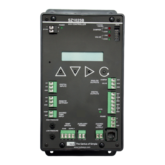
LED Description Six LEDs on the face allow the occupant to view the current operating status of the SZ1025b. POWER: This LED will be lit whenever the unit has power. CW and CCW: These four LEDs will be lit when the corresponding tri-state relay is active. The upper two indicate the relays and the lower two indicate the CW1 &...