
Related Manuals for Phantom Cables CA-1120F2-GY


Summary of Contents for Phantom Cables CA-1120F2-GY
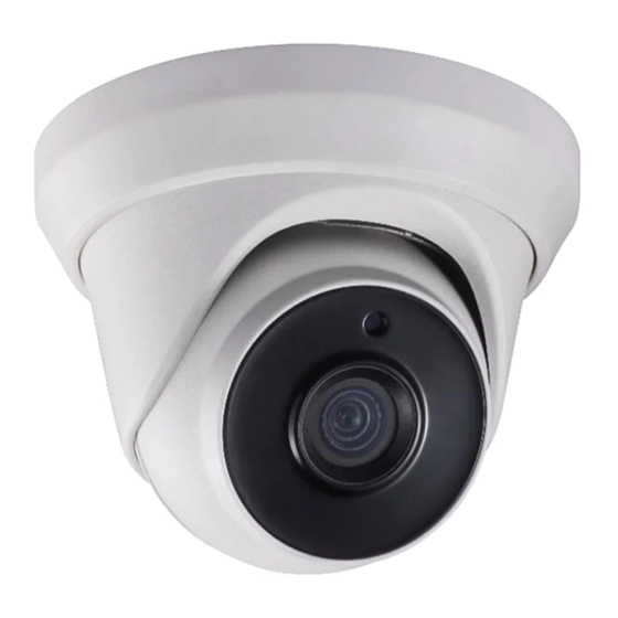
- Page 1 2 MP TURBO HD Dome, Bullet & Turret Camera CA-1120F2-WH / CA-1120F2-GY CA-1120F6-WH / CA-1420V-WH CA-1220V-WH User Manual...
-
Page 2: Regulatory Information
Regulatory Information FCC Information Please take attention that changes or modification not expressly approved by the party responsible for compliance could void the user’s authority to operate the equipment. FCC compliance: This equipment has been tested and found to comply with the limits for a Class A digital device, pursuant to part 15 of the FCC Rules. - Page 3 Safety Instruction These instructions are intended to ensure that user can use the product correctly to avoid danger or property loss. The precaution measure is divided into “Warnings” and “Cautions”. Warnings: Serious injury or death may occur if any of the warnings are neglected.
-
Page 4: Product Features
While in delivery, the camera shall be packed in its original packing, or packing of the same texture. 1 Introduction 1.1 Product Features The camera is applicable for both indoor and outdoor conditions, and the application scenarios include road, warehouse, underground parking lot, bar, etc.. -
Page 5: Installation
2 Installation Before you start: Make sure that the device in the package is in good condition and all the assembly parts are included. Make sure that all the related equipment is power-off during the installation. Check the specification of the products for the ... - Page 6 For cement wall, expansion bolts are required to fix the camera. For wooden wall, self-tapping screws are required. 5. Connect the corresponding power cord, and video cable. 6. Power on the camera to check whether the image on the monitor is gotten from the optimum angle. If not, adjust the surveillance angle.
- Page 7 Junction Box Body Screw Figure 2-5 Fix the Camera to the Ceiling 7. Route the cables through the cable hole, or the side opening of the junction box. 8. Combine the junction box cover with its body. Figure 2-6 Fix the Junction Box Cover back to its Body 9.
- Page 8 Figure 2-9 Fix the Mounting Base on the Ceiling Note: The supplied screw package contains self-tapping screws, and expansion bolts. For cement wall, expansion bolts are required to fix the camera. For wooden wall, self-tapping screws are required. 5.
- Page 9 Figure 2-12 Drill Template of the Junction Box Note: Drill the cable hole, when adopting the ceiling outlet to route the cable. 3. Refer to step 3 of 2.2.1 Ceiling/Wall Mounting without Junction Box to take out the camera’s main body.
-
Page 10: Menu Description
3 Menu Description Purpose: Call the menu by clicking button on the PTZ Control interface, or call preset No.95. Steps: 1. Connect the camera with the TVI DVR, and the monitor shown as the Figure 3-1. TVI DVR Camera Monitor Figure 3-1 Connection 2. -
Page 11: Exposure Mode
3.3 FOCUS Move the cursor to FOCUS, and press the Iris+ to enter the submenu. Click FOCUS+, FOCUS-, ZOOM+, and ZOOM- to adjust the focus. 3.4 MAIN MENU 3.4.1 AE (AUTO EXPOSURE) Auto Exposure describes the brightness-related parameters, which can be adjusted by BRIGHTNESS, EXPOSURE MODE, AGC, and SENSE UP. -
Page 12: Video Setting
the environment. It can remove unrealistic color casts in the image. You can set WB mode as ATW, or MWB. ATW (Aoto Tracking White Balance) Under ATW mode, white balance is being adjusted automatically according to the color temperature of the scene illumination. - Page 13 CONTRAST This feature enhances the difference in color and light between parts of an image. You can set the CONTRAST value from 1 to 10. SHARPNESS Sharpness determines the amount of detail an imaging system can reproduce. You can set the SHARPNESS value from 1 to 10.
-
Page 14: Save And Exit
position and size of the area. Set the SENSITIVITY from 0 to 100. CAMERA ID Edit the camera ID on this section. CAM ID SETTING MODE CAM ID X POSITION 75 Y POSITION RETURN Figure 3-9 CAM ID SETTING Set the MODE as on.