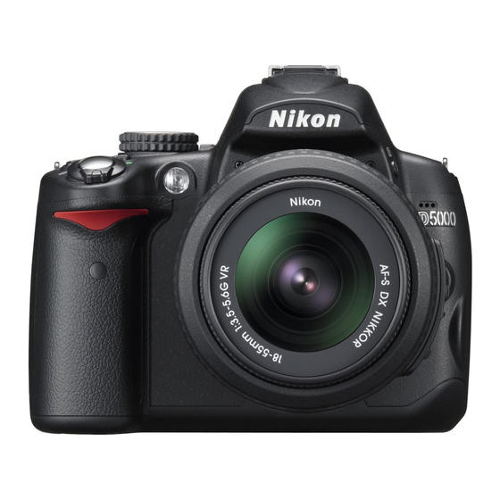
Summary of Contents for Nikon D5000
- Page 1 VBA24001-R.3783.A 作成承認印 配布許可印 サービス 計画課 M logo_Q0770 VBA24001 081219_Gdesign_ito REPAIR MANUAL Copyright c 2009 by Nikon Corporation. All Rights Reserved. 無断転載を禁ず !! Printed in Japan APRIL.2009...
- Page 2 7. Rear body ..................................D32 Microphone ................................. D32 Main condenser ................................D32 SB PCB unit ................................. D33 DC/DC PCB unit ................................ D34 Battery box .................................. D35 Eyelet unit, etc ................................D36 8. Front body ..................................D37 Shutter ..................................D37 - D5000 -...
- Page 3 Main mirror and Sub-mirror ......................A16 Shutter ..................................A25 2. Rear body ..................................A26 Eyelet unit, etc ................................A26 Battery box .................................. A27 DC/DC PCB unit ................................ A29 SB PCB unit ................................. A30 Main condenser ................................A31 - D5000 -...
- Page 4 SD cover unit ................................A66 8. External appearance ..............................A68 Accuracy inspection and adjustment (Camera body excl. imaging) ..............A69 D5000 Inspection and Adjustment Software (J65135) ..................... A70 Procedure for installation ............................A71 Procedure for installing USB driver .......................... A74 Necessary adjustments when parts are replaced ......................
- Page 5 Operation check of cleaning image sensor ......................A100 Hinge SW inspection ..............................A103 Main/sub mirror angle inspection tool - use chart ....................A104 Wiring ......................................E1 Mounting Drawing ..................................E2 Inspection standards .................................. R1 Tools ......................................T1 Screw sheet ....................................S1 - D5000 -...
- Page 6 Caution: When "Separation of Front body from Rear body", "Disassembly of Image sensor unit" and "Disassembly of Bayonet" are performed, be sure to carry out "RESET AF-DEFOCUS COMPENSATION" of the D5000 adjustment software after assembly. - D1 ・ D5000 -...
- Page 7 ・ Open and tilt the battery cover unit (#B151) at approx. 35° angle, then pull it out at the angle. ・ Open the power cable cover. ・ Take out the four screws (#735) and five screws (#671). ・ Remove the bottom cover (#25). Approx. 35° #671 #735 Power cable cover #735 - D2 ・ D5000 -...
- Page 8 There are high voltege parts inside. Be careful of this electric shock, when you remove the cover. You must discharge the main condenser according to the instruction of this repair manual after you remove the cover. 2K Ω /5W - D3 ・ D5000 -...
- Page 9 VBA24001-R.3783.A Removal of back cover ・ Take out the two screws (#618), the two screws (#690), the two screws (#697) and two screws (#740). #618 #697 #690 #740 - D4 ・ D5000 -...
- Page 10 ・ Remove the cover by lifting it at the grip side first, and then the whole. ・ Disconnect the FPC and harness (of the rear cover) from the connectors of the TOGO PCB UNIT(#B2001). ・ Remove the IF cover (#71). - D5 ・ D5000 -...
- Page 11 VBA24001-R.3783.A 2. Back cover ・ Peel off the tape (#705). #705 ・ Take out the two screws (#741). ・ Remove the hinge rear cover A (#445) and hinge rear cover B (#446). #741 #446 #445 - D6 ・ D5000 -...
- Page 12 VBA24001-R.3783.A ・ Take out the two screws (#682). ・ Remove the TFT monitor unit from the back cover. (When removing this, be careful not to catch the harness.) #682 Be careful NOT to catch. - D7 ・ D5000 -...
- Page 13 Sponge/Button/FPC/Speaker ・ Peel off the tape (#707). ・ Unsolder the speaker (#1047). #707 #478 #424 #425 #426 #421 #427 #471 #422 #472 #475 #474 #1047 #683 #412 #418 #419 #B1019 #413 #683 #707 #415 #729 - D8 ・ D5000 -...
- Page 14 ・ Remove the superglue from the SD access lamp window (#408), and remove [#408]. #706 #477 #408 Adhesive: Superglue ・ Remove the two rubbers (#473). ・ Remove the rubber (#469). ・ Peel off the double-stick tapes (#470 and #476). #473 #469 #470 #476 - D9 ・ D5000 -...
- Page 15 VBA24001-R.3783.A SD cover unit ・ Take out the two screws (#684). ・ Remove the SD cover unit (#B443). #684 #B443 ・ Peel off the label (#448). #448 - D10 ・ D5000 -...
- Page 16 ・ Pull out the shaft, and remove the SD-cover torsion spring. (Be careful NOT to lose the spring.) ・ Remove the plate from the SD cover (#443). SD-cover torsion spring Screw SD-cover click spring Shaft Plate #443 - D11 ・ D5000 -...
- Page 17 ・ Remove the TFT window (#402), and peel off the TFT window double-sticking tape (#403). ・ Remove the sensor magnet (#490) from the TFT monitor unit (#B2049). ・ Remove the magnet spacer (#494) from the sensor magnet (#490). #402 #490 #403 #494 #B2049 - D12 ・ D5000 -...
- Page 18 (Caution : must be exercised that each part do not get scratched or dented. If it does, use a new one.) #671 #438 Unhook here Unhook here #437 ・ Position [#B454] as below, and take out the two screws (#673) and two screws (#674). #673 #B454 #674 - D13 ・ D5000 -...
- Page 19 (Caution : must be exercised that each part does not get scratched or dented. If it does, use a new one.) Back #434 ・ Remove the lock knob (#431). ・ Remove the lock-plate spring (#432). #432 #431 - D14 ・ D5000 -...
- Page 20 (Caution must be exercised that the part does not get scratched or dented. If it does, use a new one.) #438 #677 ・ Unsolder the wires [Orange/Blue/Black/Red]. ・ Disconnect the harness from the connector. ・ Remove the hinge unit (#B454). [Orange/Blue/Black/Red] #B454 - D15 ・ D5000 -...


