
Related Manuals for Saitek X-56 RHINO H.O.T.A.S. SYSTEM


Summary of Contents for Saitek X-56 RHINO H.O.T.A.S. SYSTEM
- Page 1 X-56 RHINO H.O.T.A.S. SYSTEM ™ HANDS ON THROTTLE AND STICK COMBAT SERIES USER MANUAL...
- Page 2 Welcome Message from the Developers The Saitek Pro Flight team thanks you for purchasing this groundbreaking piece of Pro Flight hardware. Rest assured that, as with all the products we’ve developed over the years, a wealth of knowledge, skill, and endeavor went into the development phase. Thanks to our dedicated pool of beta testers –...
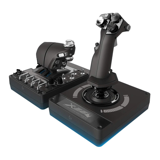
- Page 3 STICK OVERVIEW A. POV B. Thumb Pickle Button C. Thumb HATs, Witches and Castle D. Stick Buttons with Trigger Thumb Pickle: General Controls-> Boost and 2 x Head Buttons E. X, Y, and Rz Axes, Elevator, Aileron and Rudder Axes F.
- Page 4 THROTTLE OVERVIEW A. Throttle Rotaries with inset buttons B. 2-position Slider C. Thumb Controls with 2 HATs, Thumb Button, Mini AnalogStick D. Twin Throttles with Throttle Lock C) Mini Analog Stick: E. Throttle Tension Adjuster Settings-> Controls->Menu Navigation->Misc(at the bottom) F.
-
Page 5: Getting Started
8/10 (32- and 64-bit) ® A) Drivers Only 1. Download and install the X-56 Rhino Software from www.saitek.com 2. After reading the Disclaimer, select the ‘I accept the terms of the Disclaimer’ option and click ‘Next’ to continue 3. At the Plug In screen, plug the Stick and Throttle units into the PC. - Page 6 7 (32- and 64-bit) ® A) Drivers Only 1. Download and install the X-56 Rhino Drivers from www.saitek.com 2. After reading the Disclaimer, select the ‘I accept the terms of the Disclaimer’ option and click ‘Next’ to continue 3. At the Plug In screen, plug the Stick and Throttle units into the PC. Click ‘Next’ when it becomes highlighted 4.
-
Page 7: Controller Settings
CONTROLLER SETTINGS If at any time you wish to check that the X-56 is working correctly, open the Game Controllers page and click on the controller’s Properties tab. Here are the various ways to do this from each operating system: Windows 8/10 (all 32- and 64-bit versions) ®... - Page 8 From the Controller Test screen you can test all the functions, axes, buttons, rotaries, etc. When you have completed your tests, click ‘OK’ twice to get back to the main desktop...
- Page 9 F.E.E.L. Spring Tension System Each spring placed on the Rhino stick shaft will give a different feeling. You can also operate the stick without a spring, providing a total of five different forces. Each spring has a unique feel and different identification. These identifiers are color swatches at the top of each spring –...
- Page 10 Changing or removing a spring To insert, change, or remove a spring, follow these steps. Ensure the trigger is facing away from you and that the X-56 Rhino logo plate is facing you. 1. Turn the Locking Bezel (part B) counterclockwise until the Stick comes away from the base. 2.
-
Page 11: Software Overview
H.U.D. Software Overview H.U.D. Software allows you to program the X-56 Rhino with an array of keyboard commands, from basic single-key commands to very advanced, timed, and macro commands. It will also allow you to program any axis with keyboard commands, and program mouse commands. In the H.U.D. - Page 12 Related products that we feel that you would be interested in Live Facebook feed from Saitek Pro Flight Social media and website short cuts, Saitek.com, Twitter, YouTube, Instagram, etc Language selection, use the flag icon in the bottom-right corner to access this...
- Page 13 PROGRAMMING TAB After selecting the PROGRAMMING Tab you will see the X-56’s programming environment. You will see a high-resolution image of the controller you are going to program on the left side of the screen. On the right side of the screen you will see a list of command boxes, called “Cells,” going down the page.
- Page 14 Making your first Profile 1. Either hover the mouse pointer over the Cell, or press the button you want to create a Profile for on the controller. If you hover your mouse over the Button ‘A’ Cell, Button ‘A’ will light up on the 3D Joystick image.
- Page 15 5. Test your Profile by opening the “Testing” window. Above the 3D image there are seven icons. The one that is second from the right, which looks like a silver cog, is labeled “Test Profile.” Click on this icon and a new window will open. A cursor will already be flashing in the test area.
- Page 16 Icons in the Profile Editor 1. New Profile Opens a blank Profile for you to edit/build. 2. Open Profile Opens a previously created Profile for editing. 3. Save Profile Clicking “Save” will save a new Profile or overwrite a current Profile. Using the drop-down arrow next to “Save,”...
- Page 17 Settings The settings page will allow you to alter the deadzone and response curves of all axes on both the Stick and the Throttle. Response Curves Depending on the type of aircraft that you fly, you may want your joystick to be more or less sensitive around the middle or end points of the axes.
- Page 18 Once you are in the ‘STICK // AXIS MODIFICATION’ screen, you’ll see a raft of options. We’ll go through them one by one. 1. Name of the Part being Modified 2. Modifiable Axes 3. Manual Axis Adjustment and Test Area 4.
-
Page 19: Back Button
1. Name of the Part being Modified This will either be the Stick or the Throttle unit for the X-56. If you wish to change the part that you’re not currently on, use the back button (5) to go back to the selection screen. 2. -
Page 20: Apply Button
7. Manual Axis Attribute Boxes This area allows you to input raw data to setup your deadband, curvature, range saturation, and physical saturation settings. This is very useful if you already have the data or a third-party source is supplying the data. - Page 21 Altering Axis Attributes Axis Status Notifications You’ll need to be aware of several notifications in the axis highlighter box when manipulating and applying axis data. On the left is a list of the current device’s axes. The colors indicate the status of each axis.
- Page 22 Setting a Physical Axis To set the physical axis range on any axis, move the Physical Axis Adjustment Slider (part 6). Moving this slider will shrink the minimum and maximum range of the physical axis. After moving the sliders to set your axis, every time you move the physical axis you'll see that the minimum and maximum range has shrunk.
-
Page 23: Knowledge Base
View Online Videos of the X-56 Rhino Clicking this icon will launch the X-56 YouTube channel. A number of videos on this channel will ® highlight the X-56 Rhino’s standout features. View the Manual in PDF Format Opens up a PDF version of this Manual. View the Quick Start Guide (QSG) in PDF Format Opens up a PDF version of the Quick Start Guide. -
Page 24: Troubleshooting
Q7 Why are my axes off center or moving erratically? A 1. Please visit the FAQ page in the support section of the Saitek webpage to find simple instructions on how to reset the calibration. All addresses are listed within the Technical Support area of this manual. -
Page 25: Technical Support
TECHNICAL SUPPORT Can’t get started? Don’t worry; we’re here to help you! Nearly all the products that are returned to us as faulty are not faulty at all - they have just not been installed properly. If you experience any difficulty with this product, please first visit our website http://support.madcatz.com.