Table of Contents
Advertisement
Quick Links
Advertisement
Table of Contents
Troubleshooting

Related Manuals for Supermicro SuperWorkstation SYS-531A-IL


Summary of Contents for Supermicro SuperWorkstation SYS-531A-IL
- Page 1 SuperWorkstation SYS-531A-IL USER’S MANUAL Revision 1.0...
- Page 2 State of California, USA. The State of California, County of Santa Clara shall be the exclusive venue for the resolution of any such disputes. Supermicro's total liability for all claims will not exceed the price paid for the hardware product.
- Page 3 If you have any questions, please contact our support team at: support@supermicro.com This manual may be periodically updated without notice. Please check the Supermicro website for possible updates to the manual revision level. Secure Data Deletion A secure data deletion tool designed to fully erase all data from storage devices can be found on our website: https://www.supermicro.com/about/policies/disclaimer.cfm?url=/wdl/utility/...
-
Page 4: Table Of Contents
Contents Contents Chapter 1 Introduction 1.1 Overview ..........................8 1.2 System Features ........................9 Front View ...........................9 Control Panel .........................10 Rear View ..........................11 Side View ..........................12 1.3 Motherboard Layout ......................13 Quick Reference Table ......................14 System Block Diagram ......................16 Chapter 2 Workstation Installation 2.1 Overview ..........................17 2.2 Unpacking the System .......................17 2.3 Preparing for Setup ......................17... - Page 5 Contents 3.8 Power Supply ........................39 Chapter 4 Motherboard Connections 4.1 Power Connections ......................41 4.2 Headers and Connectors ....................43 Control Panel .........................47 4.3 Input/Output Ports ......................50 Rear I/O Ports ........................50 4.4 Jumpers ..........................54 How Jumpers Work ......................54 4.5 LED Indicators ........................57 Chapter 5 Software 5.1 Microsoft Windows OS Installation ..................59 5.2 Driver Installation ........................61...
- Page 6 7.7 Reporting an Issue ......................78 Technical Support Procedures ..................78 Returning Merchandise for Service ...................78 Vendor Support Filing System ..................79 7.8 Feedback ..........................79 7.9 Contacting Supermicro .......................80 Appendix A Standardized Warning Statements for AC Systems Appendix B System Specifications BSMI/RoHS ..........................103...
- Page 7 Super Micro Computer, Inc. 980 Rock Ave. San Jose, CA 95131 U.S.A. Tel: +1 (408) 503-8000 Fax: +1 (408) 503-8008 Email: marketing@supermicro.com (General Information) support@supermicro.com (Technical Support) Website: www.supermicro.com Europe Address: Super Micro Computer B.V. Het Sterrenbeeld 28, 5215 ML...
-
Page 8: Chapter 1 Introduction
Mid-Tower (WxHxD) 7.6 x 16.7 x 21.2 in. (193 x 424 x 536 mm) A Quick Reference Guide can be found on the product page of the Supermicro website. The following safety models associated with the SYS-531A-IL have been certified as compliant with UL or CSA: 735-6, 735D4-S6X13. -
Page 9: System Features
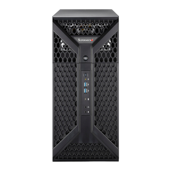
Chapter 1: Introduction 1.2 System Features The SYS-531A-IL is a mid-tower barebone workstation system designed for small and medium- sized businesses. The workstation can be proposed-built and configured for professional video editing, 3D modeling, or other professional applications. The following views of the system display the main features. -
Page 10: Control Panel
Chapter 1: Introduction Control Panel Power HDD LED USB (Type C) Line-out Mic In Figure 1-2. Control Panel Control Panel Features Feature Description The main power switch applies or removes primary power from the power Power Button with LED supply to the workstation but maintains standby power. HDD LED Indicates activity on the storage drives when flashing. -
Page 11: Rear View
Chapter 1: Introduction Rear View Power Supply Rear I/O Ports Expansion Slots Figure 1-3. System: Rear View System Features: Rear Feature Description Power Supply One PS2 668W multi-output 80+ Platinum power supply Rear Exhaust Fan One 12cm fan Rear I/O Backpanel For details, see 4.3 Input/Output Ports. -
Page 12: Side View
Chapter 1: Introduction Side View Power Supply 5.25" Drive Bays 3.5" Drive Trays Optional 2.5" Drive Cage Optional Fan Module Figure 1-4. System: Side View System Features: Side Feature Description Power Supply One 668W 80PLUS Platinum PS2 power supply 5.25" Drive Bays Two 5.25"... -
Page 13: Motherboard Layout
Chapter 1: Introduction 1.3 Motherboard Layout Below is a layout of the X13SAE motherboard with jumper, connector and LED locations shown. See the table on the following page for descriptions. For detailed descriptions, pinout information and jumper settings, refer to Chapter 4 or the Motherboard Manual. -
Page 14: Quick Reference Table
Chapter 1: Introduction Quick Reference Table Jumper Description Default Setting JBT1 Clear CMOS (Onboard) Short pads to clear CMOS Pins 1-4: External Speaker Speaker/Buzzer Pins 3-4: Buzzer (Default) JPAC1 HD Audio Enable/Disable Pins 1-2 (Enabled) JPL1, JPL2 LAN1/LAN2 Enable/Disable Pins 1-2 (Enabled) JPME2 ME Manufacturing Mode Pins 1-2 (Normal) - Page 15 Chapter 1: Introduction Connector Description 12V_PUMP_PWR1 12V 4-pin Power Connector (for CPU liquid cooling pump) AUDIO Back Panel High Definition Audio Ports AUDIO_FP Front Panel Audio Header Onboard Battery COM1 COM Header CPU_FAN1, CPU_FAN2 CPU_FAN1, CPU_FAN2: CPU Fan Headers SYS_FAN1 - SYS_FAN3 SYS_FAN1 - SYS_FAN3: System Fan Headers Back Panel DisplayPort (1.4a) HDMI...
-
Page 16: System Block Diagram
Chapter 1: Introduction System Block Diagram The block diagram below shows the connections and relationships between the subsystems and major components of the overall system. X13SAE CPU_PE5*8 PCIe x16 SLOT #7 PCIe Gen5 CPU_PE5*8 Mux/DeMux SVID IMVP9.1 VR PESLOT4_PRSNT_N INTEL LGA1700 PCIe x8 SLOT #4 DDR5 (CHA) DIMMA1... -
Page 17: Chapter 2 Workstation Installation
PCBs by their edges and keep them in anti-static bags when not in use. 2.2 Unpacking the System Inspect the box in which the SuperWorkstation SYS-531A-IL was shipped, and note if it was damaged in any way. If any equipment appears damaged, file a damage claim with the carrier who delivered it. - Page 18 Chapter 2: Workstation Installation • Use a regulating uninterruptible power supply (UPS) to protect the workstation from power surges, voltage spikes and to keep your system operating in case of a power failure. • Allow the power supply unit to cool before touching it. •...
-
Page 19: Chapter 3 Maintenance And Component Installation
Chapter 3: Maintenance and Component Installation Chapter 3 Maintenance and Component Installation This chapter provides instructions on installing and replacing main system components. To prevent compatibility issues, only use components that match the specifications and/or part numbers given. Installation or replacement of most components require that power first be removed from the system. -
Page 20: Accessing The System
Chapter 3: Maintenance and Component Installation 3.2 Accessing the System The CSE-735D4-668B has removable side and front covers for interior access. Removing the Side Cover 1. Begin by removing power from the system, follow instructions in section 3.1. 2. Remove the two screws securing the left side cover to the chassis. 3. -
Page 21: Processor And Heatsink Installation
Thermal grease is pre-applied on a new heatsink. No additional thermal grease is needed. • Refer to the Supermicro website for updates on processor support. • All graphics in this manual are for illustrations only. Your components may look different. - Page 22 Chapter 3: Maintenance and Component Installation 2. Gently push down the load lever to release and lift it, then lift the load plate to open it completely. Lever lock 3. Use your thumb and your index finger to hold the CPU. Align the small triangle marker and notches on the CPU to the corresponding triangle marker and notches on the CPU load bracket.
- Page 23 Chapter 3: Maintenance and Component Installation 6. Close the load plate with the CPU inside the socket. Gently push the load lever down until it locks under the Lever Lock latch. Lever lock Attention! You can only install the CPU inside the socket in one direction. Make sure that it is properly inserted into the CPU socket before closing the load plate.
-
Page 24: Installing A Cpu Heatsink
Chapter 3: Maintenance and Component Installation Installing a CPU Heatsink Note 1: The installation described in this section is for reference only. The actual in- stallation steps may vary depending on the CPU heatsink model. Please refer to the heatsink instruction for more details. Note 2: Graphic drawings included in this manual are for reference only. - Page 25 Chapter 3: Maintenance and Component Installation 3. Attach the backplate into the mounting holes around the CPU socket on the bottom side of the motherboard. Backplate bottom side Motherboard bottom side Mounting hole Motherboard Top side...
- Page 26 Chapter 3: Maintenance and Component Installation 4. Apply the proper amount of thermal grease on the CPU. 5. Place the heatsink on top of the CPU so that the four mounting holes on the heatsink are aligned with those on the retention mechanism. 6.
-
Page 27: Removing A Cpu Heatsink
Chapter 3: Maintenance and Component Installation Removing a CPU Heatsink Warning: We do not recommend that the CPU or heatsink be removed. However, if you do need to remove the heatsink, please follow the instruction below to uninstall the heatsink to avoid damaging the CPU or other components. -
Page 28: Memory
The X13SAE supports up to 128GB of DDR5 Unbuffered DIMM (UDIMM) ECC/non-ECC with speeds of up to 4400MHz. Note: Check the Supermicro website for recommended memory modules. Important: Exercise extreme care when installing or removing DIMM modules to pre vent any possible damage. -
Page 29: Dimm Installation
Chapter 3: Maintenance and Component Installation DIMM Installation 1. Insert DIMM modules in the following AUDIO_FP HDMI AUDIO LAN2 LAN1 USB0/1 USB8/9 (3.2 (10Gb)) USB7 (3.2 (10Gb)) USB10 (3.2 (20Gb)) BMC_HB_LED JPL2 order: DIMMA2, DIMMB2, then DIMMA1, CPU_FAN1 JPL1 JPAC1 DIMMB1. -
Page 30: Installation
Chapter 3: Maintenance and Component Installation M.2 Installation This motherboard has three PCIe 4.0 M.2 M-key sockets that support the M.2 2280 module. One 2280 standoff is pre-installed into the position of 2280 BIOS LICENSE mounting hole. Refer to the illustration on the right X13SAE-F REV:1.00 DESIGNED IN USA... -
Page 31: Pci Expansion Card Installation
Chapter 3: Maintenance and Component Installation PCI Expansion Card Installation After the motherboard has been installed, expansion cards may be installed. Installing Expansion Cards 1. Begin by removing power from the system as described in Section 3.1 and remove the side cover as described in section 3.2. -
Page 32: Motherboard Battery
Chapter 3: Maintenance and Component Installation 3.5 Motherboard Battery The motherboard uses non-volatile memory to retain system information when system power is removed. This memory is powered by a lithium battery residing on the motherboard. Replacing the Battery Begin by removing power from the system. -
Page 33: Storage Drives
Chapter 3: Maintenance and Component Installation 3.6 Storage Drives The SYS-531A-IL supports four internal 3.5" SATA drives installed in a rotating cage. Release Tab (A) HDD Cage (B) Figure 3-4. Rotating the Internal Hard Drive Cage Rotating the Hard Drive Cage 1. - Page 34 Chapter 3: Maintenance and Component Installation Release Tabs Figure 3-5. Remove a Drive Carrier from the Cage Removing and Installing 3.5" Hard Drives 1. Begin by removing power from the system as described in Section 3.1 and remove the side cover as described in section 3.2.
- Page 35 Chapter 3: Maintenance and Component Installation Figure 3-6. Remove a Drive Carrier from the Cage 6. If a hard drive is already present, pull the sides of the carrier and remove the drive from the carrier. 7. Insert a new drive into the carrier and push the sides of the carrier together. 8.
- Page 36 Chapter 3: Maintenance and Component Installation Optional Screw Figure 3-7. Installing a Hard Drive...
-
Page 37: System Cooling
Chapter 3: Maintenance and Component Installation 3.7 System Cooling The cooling system for the SYS-531A-IL includes a 12-cm pulse-width modulated fan at the chassis rear and an optional fan at the chassis front. An air shroud directs air flow to the CPU for optimized cooling. - Page 38 Chapter 3: Maintenance and Component Installation Figure 3-9. Installing the Front Fan Replacing or Installing the Front Fan Remove power from the system as described in Section 3.1 and remove the side cover as described in section 3.2. 2. Insert the four rubber pins through the front fan bracket and into the mounting holes in the front fan.
-
Page 39: Power Supply
Chapter 3: Maintenance and Component Installation 3.8 Power Supply The SuperWorkstation SYS-531A-IL includes one PS2/ATX 668W 80Plus Platinum power supply. The power supply is auto-switching capable. This feature enables it to automatically sense the input voltage and operate at a 100-240Vac, 60-50Hz, 8-4A. - Page 40 Chapter 3: Maintenance and Component Installation Remove Screws Figure 3-10. Removing the Power Supply Screws Note: The figure is for illustrative purposes only. Some components may differ on the SYS-531A-IL.
-
Page 41: Chapter 4 Motherboard Connections
Chapter 4: Motherboard Connections Chapter 4 Motherboard Connections This section describes the connections on the motherboard and provides pinout definitions. Note that depending on how the system is configured, not all connections are required. The LEDs on the motherboard are also described here. A motherboard layout indicating component locations may be found in Chapter 1. - Page 42 Chapter 4: Motherboard Connections 8-Pin Power Connector JPW2 is an 8-pin 12V DC power input for the CPU that must be connected to the power supply. Refer to the table below for pin definitions. 8-pin Power Pin Definitions Pin# Definition Ground +12V Required Connection...
-
Page 43: Headers And Connectors
Chapter 4: Motherboard Connections 4.2 Headers and Connectors Fan Headers There are five 4-pin fan headers (CPU_FAN1, CPU_FAN2, SYS_FAN1 - SYS_FAN3) on the motherboard. Although pins 1-3 of the system fan headers are backwards compatible with the traditional 3-pin fans, the 4-pin fans are recommended to take advantage of the fan speed control. - Page 44 Chapter 4: Motherboard Connections Standby Power Header The Standby Power header is located at JSTBY1 on the motherboard. Refer to the table below for pin definitions. Standby Power Header Pin Definitions Pin# Definition +5V Standby Ground DOM Power Connector The Disk-On-Module (DOM) Power connector, located at JSD1, provides 5V power to a solid state DOM storage device connected to one of the SATA ports.
- Page 45 SATA RAID (0, 1, 5, and 10) with up to six SATA storage devices. Note: For more information on the SATA HostRAID configuration, please refer to the Intel SATA HostRAID user's guide posted on our website at https://www.supermicro.com/sup- port/manuals/. SATA 3.0 Ports...
- Page 46 Port 80 connection. Use this header to enhance system performance and data security. Refer to the table below for pin definitions. Please go to the following link for more information on the TPM: http://www.supermicro.com/manuals/other/TPM.pdf. TPM/Port 80 Header Pin Definitions...
-
Page 47: Control Panel
These connectors are designed specifically for use with Supermicro chassis. Refer to the figure below for the descriptions of the front control panel buttons and LED indicators. - Page 48 Chapter 4: Motherboard Connections Reset Button The Reset Button connection is located on pins 3 and 4 of JF1. Attach it to a hardware reset switch on the computer case to reset the system. Refer to the table below for pin definitions. Reset Button Pin Definitions (JF1) Pin#...
- Page 49 Chapter 4: Motherboard Connections HDD LED The HDD LED/UID Switch connection is located on pins 13 and 14 of JF1. Attach a cable to pin 14 to show hard drive activity status. HDD LED Pin Definitions (JF1) Pin# Definition HD Active Power LED The Power LED connection is located on pins 15 and 16 of JF1.
-
Page 50: Input/Output Ports
Chapter 4: Motherboard Connections 4.3 Input/Output Ports Rear I/O Ports See the figure below for the locations and descriptions of the I/O ports on the rear of the motherboard. AUDIO_FP HDMI AUDIO LAN2 LAN1 USB0/1 USB8/9 (3.2 (10Gb)) USB7 (3.2 (10Gb)) USB10 (3.2 (20Gb)) BMC_HB_LED JPL2... - Page 51 Chapter 4: Motherboard Connections Universal Serial Bus (USB) Connections There are two USB 2.0 Type-A ports (USB0, USB1), three USB 3.2 Gen. 2x1 Type-A ports (USB7, USB8, USB9), and one USB 3.2 Gen. 2x2 Type-C port (USB10) are located on the I/O back panel.
- Page 52 Chapter 4: Motherboard Connections Back Panel High Definition Audio (HD Audio) This motherboard features a 7.1+2 Channel High Definition Audio (HDA) codec that provides 10 DAC channels. The HD Audio connections simultaneously supports multiple-streaming 7.1 sound playback with 2 channels of independent stereo output through the front panel stereo out for front, rear, center, and subwoofer speakers.
- Page 53 Chapter 4: Motherboard Connections LAN Ports Two Gigabit Ethernet ports (LAN1, LAN2) are located on the I/O back panel. In addition, a dedicated IPMI LAN port (IPMI_LAN) is located above the USB0/USB1 ports on the I/O back panel. All of these ports accept RJ45 cables. LAN1 Port LAN2 Port Pin Definitions...
-
Page 54: Jumpers
Chapter 4: Motherboard Connections 4.4 Jumpers How Jumpers Work To modify the operation of the motherboard, jumpers can be used to choose between optional settings. Jumpers create shorts between two pins to change the function of the connector. Pin 1 is identified with a square solder pad on the printed circuit board. Refer to the diagram below for an example of jumping pins 1 and 2. - Page 55 Chapter 4: Motherboard Connections Clear CMOS Clear CMOS (JBT1) is used to clear the saved system setup configuration stored in the CMOS chip. To clear the contents of the CMOS using JBT1, short the two pads of JBT1 with metallic conductor such as a flathead screwdriver. This will erase all user settings and revert everything to their factory-set defaults.
- Page 56 Chapter 4: Motherboard Connections Audio Enable/Disable JPAC1 allows you to enable or disable the onboard audio support. The default setting is pins 1-2 to enable onboard audio connections. Refer to the table below for jumper settings. Audio Enable/Disable Jumpers Settings Jumper Setting Definition Pins 1-2...
-
Page 57: Led Indicators
Chapter 4: Motherboard Connections 4.5 LED Indicators LAN1/LAN2 LEDs The LED on the left indicates the speed of the connection, and the LED on the right indicates activity. Refer to the tables below for more information. LAN2 Speed LED (Left) LAN1 Speed LED (Left) LAN1/LAN2 Activity LED (Right) LED State... - Page 58 Chapter 4: Motherboard Connections BMC Heartbeat LED BMC Heartbeat LED (BMC_HB_LED) is located next to the PCIe SLOT5 on the motherboard. Refer to the table below for more information. BMC Heartbeat LED (BMC_HB_LED) LED Status Motherboard Color Status X13SAE Solid Green Standby Power On CATERR LED A CATERR LED is located at CATERR_LED.
-
Page 59: Chapter 5 Software
1. Create a method to access the MS Windows installation ISO file. That might be a DVD, perhaps using an external USB/SATA DVD drive, or a USB flash drive. 2. Retrieve the proper RST/RSTe driver. Go to the Supermicro web page for your motherboard and click on "Download the Latest Drivers and Utilities", select the proper driver, and copy it to a USB flash drive. - Page 60 Chapter 5: Software 4. During Windows Setup, continue to the dialog where you select the drives on which to install Windows. If the disk you want to use is not listed, click on “Load driver” link at the Figure 5-2. Load Driver Link bottom left corner.
-
Page 61: Driver Installation
The Supermicro website contains drivers and utilities for your system at https://www. supermicro.com/wdl/. Some of these must be installed, such as the chipset driver. After accessing the website, go into the CDR_Images (in the parent directory of the above link) and locate the ISO file for your motherboard. Download this file to a USB flash drive or a DVD. -
Page 62: Superdoctor ® 5
5.3 SuperDoctor ® The Supermicro SuperDoctor 5 is a program that functions in a command-line or web-based interface for Windows and Linux operating systems. The program monitors such system health information as CPU temperature, system voltages, system power consumption, fan speed, and provides alerts via email or Simple Network Management Protocol (SNMP). -
Page 63: Chapter 6 Optional Components
FAN-0124L4 6.2 Mobile Rack The SuperWorkstation SYS-531A-IL allows to install an optional Supermicro mobile rack (CSE-M14TQC or CSE-M28SACB) in place of one or two 5.25" bays. The CSE-M14TQC supports four 2.5" solid state disk drive bays with SATA3 or SAS3 connections and takes up one 5.25"... - Page 64 Chapter 6: Optional Components Installing the Mobile Rack 1. Remove one tray or two adjacent trays from the chassis. 2. Remove the drive tray rails. 3. Install a drive tray rail onto each side of the mobile rack. Make sure the arrow on the rail points toward the front of the chassis.
-
Page 65: Chapter 7 Troubleshooting And Support
Chapter 7 Troubleshooting and Support 7.1 Information Resources Website A great deal of information is available on the Supermicro website, www.supermicro.com. Products Figure 7-1. Supermicro Website • Specifications for workstations and other hardware are available by clicking on Products. • The Support option offers downloads (manuals, BIOS/BMC, drivers, etc.), FAQs, RMA, warranty, and other service extensions. - Page 66 Chapter 7: Troubleshooting and Support Direct Links (continued) Product Matrices page for links to tables summarizing specs for systems, motherboards, power supplies, riser cards, add-on cards, etc. Security Center for recent security notices Supermicro Phone and Addresses...
-
Page 67: Troubleshooting Procedures
Chapter 7: Troubleshooting and Support 7.2 Troubleshooting Procedures Use the following procedures to troubleshoot your system. If you have followed all of the procedures below and still need assistance, refer to the Technical Support Procedures Returning Merchandise for Service section(s) in this chapter. Power down the system before changing any non-hot-swap hardware components. -
Page 68: No Power To The System
Chapter 7: Troubleshooting and Support 2. Set all jumpers to their default positions. 3. Power up. If the system boots, check for memory errors and add-on card problems. No Power to the System • Check that the power LED on the motherboard is on. •... -
Page 69: Memory Errors
• System cooling: Check that all heatsink fans and system fans work properly. • Adequate power supply: Make sure that the power supply provides adequate power to the system. Make sure that all power connectors are connected. Refer to the Supermicro website for the minimum power requirements. - Page 70 Chapter 7: Troubleshooting and Support • Cable connection: Check to make sure that all cables are connected and working properly. • Use the minimum configuration for troubleshooting: Remove all unnecessary components (starting with add-on cards first), and use the minimum configuration (but with a CPU and a memory module installed) to identify the trouble areas.
-
Page 71: Bios Error Beep (Post) Codes
When BIOS performs the Power On Self Test, it writes checkpoint codes to I/O port 0080h. If the computer cannot complete the boot process, a diagnostic card can be attached to the computer to read I/O port 0080h (Supermicro p/n AOC-LPC80-20). For information on AMI updates, please refer to http://www.ami.com/products/. -
Page 72: Uefi Bios Recovery
Warning: Do not upgrade the BIOS unless your system has a BIOS-related issue. Flashing the wrong BIOS can cause irreparable damage to the system. In no event shall Supermicro be liable for direct, indirect, special, incidental, or consequential damages arising from a BIOS update. - Page 73 USB device or a writable CD/DVD. Note 1: If you cannot locate the "Super.ROM" file in your drive disk, visit our website at www.supermicro.com to download the BIOS package. Extract the BIOS binary image into a USB flash device and rename it "Super.ROM" for the BIOS recovery use.
- Page 74 Chapter 7: Troubleshooting and Support Note: At this point, you may decide if you want to start the BIOS recovery. If you decide to proceed with BIOS recovery, follow the procedures below. 4. When the screen as shown above displays, use the arrow keys to select the item "Proceed with flash update"...
- Page 75 Chapter 7: Troubleshooting and Support 7. Press <Del> continuously during system boot to enter the BIOS Setup utility. From the top of the toolbar, select Boot to enter the submenu. From the submenu list, select Boot Option #1 as shown below. Then, set Boot Option #1 to [UEFI AP:UEFI: Built-in EFI Shell]. Press <F4>...
- Page 76 Chapter 7: Troubleshooting and Support Note: Do not interrupt this process until the BIOS flashing is complete. 9. The screen above indicates that the BIOS update process is complete. When you see the screen above, unplug the AC or DC power cable from the power supply, clear CMOS, and plug the AC or DC power cable in the power supply again to power on the system.
-
Page 77: Cmos Clear
Chapter 7: Troubleshooting and Support 7.5 CMOS Clear JBT1 is used to clear CMOS, which will also clear any passwords. Instead of pins, this jumper consists of contact pads to prevent accidentally clearing the contents of CMOS. To Clear CMOS 1. -
Page 78: Where To Get Replacement Components
7.6 Where to Get Replacement Components If you need replacement parts for your system, to ensure the highest level of professional service and technical support, purchase exclusively from our Supermicro Authorized Distributors/System Integrators/Resellers. A list can be found at: http://www.supermicro.com. -
Page 79: Vendor Support Filing System
For issues related to Red Hat Enterprise Linux, since it is a subscription based OS, contact your account representative. 7.8 Feedback Supermicro values your feedback as we strive to improve our customer experience in all facets of our business. Please email us at techwriterteam@supermicro.com to provide feedback on our manuals. -
Page 80: Contacting Supermicro
Chapter 7: Troubleshooting and Support 7.9 Contacting Supermicro Headquarters Address: Super Micro Computer, Inc. 980 Rock Ave. San Jose, CA 95131 U.S.A. Tel: +1 (408) 503-8000 Fax: +1 (408) 503-8008 Email: marketing@supermicro.com (General Information) support@supermicro.com (Technical Support) Website: www.supermicro.com Europe Address: Super Micro Computer B.V. -
Page 81: Appendix A Standardized Warning Statements For Ac Systems
Supermicro's Technical Support department for assistance. Only certified technicians should attempt to install or configure components. Read this appendix in its entirety before installing or configuring components in the Supermicro chassis. These warnings may also be found on our website at http://www.supermicro.com/about/... - Page 82 Appendix A: Standardized Warning Statements for AC Systems Warnung WICHTIGE SICHERHEITSHINWEISE Dieses Warnsymbol bedeutet Gefahr. Sie befinden sich in einer Situation, die zu Verletzungen führen kann. Machen Sie sich vor der Arbeit mit Geräten mit den Gefahren elektrischer Schaltungen und den üblichen Verfahren zur Vorbeugung vor Unfällen vertraut. Suchen Sie mit der am Ende jeder Warnung angegebenen Anweisungsnummer nach der jeweiligen Übersetzung in den übersetzten Sicherheitshinweisen, die zusammen mit diesem Gerät ausgeliefert wurden.
- Page 83 Appendix A: Standardized Warning Statements for AC Systems . ٌ ا ك ً ف حالة و ٌ يك أى تتسبب ف اصابة جسذ ة ٌ هذا الزهز ع ٌ خطز !تحذ ز قبل أى تعول عىل أي هعذات،يك عىل علن بالوخاطز ال ا ٌجوة عي الذوائز ٍ...
- Page 84 Appendix A: Standardized Warning Statements for AC Systems Warnung Vor dem Anschließen des Systems an die Stromquelle die Installationsanweisungen lesen. ¡Advertencia! Lea las instrucciones de instalación antes de conectar el sistema a la red de alimentación. Attention Avant de brancher le système sur la source d'alimentation, consulter les directives d'installation. .יש...
- Page 85 Appendix A: Standardized Warning Statements for AC Systems Warnung Dieses Produkt ist darauf angewiesen, dass im Gebäude ein Kurzschluss- bzw. Überstromschutz installiert ist. Stellen Sie sicher, dass der Nennwert der Schutzvorrichtung nicht mehr als: 250 V, 20 A beträgt. ¡Advertencia! Este equipo utiliza el sistema de protección contra cortocircuitos (o sobrecorrientes) del edificio.
- Page 86 Appendix A: Standardized Warning Statements for AC Systems Power Disconnection Warning Warning! The system must be disconnected from all sources of power and the power cord removed from the power supply module(s) before accessing the chassis interior to install or remove system components. 電源切断の警告...
- Page 87 Appendix A: Standardized Warning Statements for AC Systems אזהרה מפני ניתוק חשמלי !אזהרה יש לנתק את המערכת מכל מקורות החשמל ויש להסיר את כבל החשמלי מהספק .לפני גישה לחלק הפנימי של המארז לצורך התקנת או הסרת רכיבים يجب فصم اننظاو من جميع مصادر انطاقت وإ ز انت سهك انكهرباء من وحدة امداد انطاقت...
- Page 88 Appendix A: Standardized Warning Statements for AC Systems Attention Il est vivement recommandé de confier l'installation, le remplacement et la maintenance de ces équipements à des personnels qualifiés et expérimentés. !אזהרה .צוות מוסמך בלבד רשאי להתקין, להחליף את הציוד או לתת שירות עבור הציוד واملدربيه...
- Page 89 Appendix A: Standardized Warning Statements for AC Systems Warnung Diese Einheit ist zur Installation in Bereichen mit beschränktem Zutritt vorgesehen. Der Zutritt zu derartigen Bereichen ist nur mit einem Spezialwerkzeug, Schloss und Schlüssel oder einer sonstigen Sicherheitsvorkehrung möglich. ¡Advertencia! Esta unidad ha sido diseñada para instalación en áreas de acceso restringido. Sólo puede obtenerse acceso a una de estas áreas mediante la utilización de una herramienta especial, cerradura con llave u otro medio de seguridad.
- Page 90 Appendix A: Standardized Warning Statements for AC Systems Battery Handling Warning! There is the danger of explosion if the battery is replaced incorrectly. Replace the battery only with the same or equivalent type recommended by the manufacturer. Dispose of used batteries according to the manufacturer's instructions 電池の取り扱い...
- Page 91 Appendix A: Standardized Warning Statements for AC Systems هناك خطر من انفجار يف حالة اسحبذال البطارية بطريقة غري صحيحة فعليل اسحبذال البطارية فقط بنفس النىع أو ما يعادلها مام أوصث به الرشمة املصنعة جخلص من البطاريات املسحعملة وفقا لحعليامت الرشمة الصانعة 경고! 배터리가...
- Page 92 Appendix A: Standardized Warning Statements for AC Systems ¡Advertencia! Puede que esta unidad tenga más de una conexión para fuentes de alimentación. Para cortar por completo el suministro de energía, deben desconectarse todas las conexiones. Attention Cette unité peut avoir plus d'une connexion d'alimentation. Pour supprimer toute tension et tout courant électrique de l'unité, toutes les connexions d'alimentation doivent être débranchées.
- Page 93 Appendix A: Standardized Warning Statements for AC Systems Backplane Voltage Warning! Hazardous voltage or energy is present on the backplane when the system is operating. Use caution when servicing. バックプレーンの電圧 システムの稼働中は危険な電圧または電力が、 バックプレーン上にかかっています。 修理する際には注意く ださい。 警告 当系统正在进行时,背板上有很危险的电压或能量,进行维修时务必小心。 警告 當系統正在進行時,背板上有危險的電壓或能量,進行維修時務必小心。 Warnung Wenn das System in Betrieb ist, treten auf der Rückwandplatine gefährliche Spannungen oder Energien auf.
- Page 94 Appendix A: Standardized Warning Statements for AC Systems هناك خطز مه التيار الكهزبايئ أوالطاقة املىجىدة عىل اللىحة عندما يكىن النظام يعمل كه حذ ر ا عند خدمة هذا الجهاس 경고! 시스템이 동작 중일 때 후면판 (Backplane)에는 위험한 전압이나 에너지가 발생 합니다. 서비스...
- Page 95 Appendix A: Standardized Warning Statements for AC Systems תיאום חוקי החשמל הארצי !אזהרה .התקנת הציוד חייבת להיות תואמת לחוקי החשמל המקומיים והארציים تركيب املعدات الكهربائية يجب أن ميتثل للقىاويه املحلية والىطىية املتعلقة بالكهرباء 경고! 현 지역 및 국가의 전기 규정에 따라 장비를 설치해야 합니다. Waarschuwing Bij installatie van de apparatuur moet worden voldaan aan de lokale en nationale elektriciteitsvoorschriften.
- Page 96 Appendix A: Standardized Warning Statements for AC Systems Attention La mise au rebut ou le recyclage de ce produit sont généralement soumis à des lois et/ou directives de respect de l'environnement. Renseignez-vous auprès de l'organisme compétent. סילוק המוצר !אזהרה .סילוק סופי של מוצר זה חייב להיות בהתאם להנחיות וחוקי המדינה التخلص...
- Page 97 Appendix A: Standardized Warning Statements for AC Systems Warnung Gefährlich Bewegende Teile. Von den bewegenden Lüfterblätter fern halten. Die Lüfter drehen sich u. U. noch, wenn die Lüfterbaugruppe aus dem Chassis genommen wird. Halten Sie Finger, Schraubendreher und andere Gegenstände von den Öffnungen des Lüftergehäuses entfernt.
- Page 98 Verbindungskabeln, Stromkabeln und/oder Adapater, die Ihre örtlichen Sicherheitsstandards einhalten. Der Gebrauch von anderen Kabeln und Adapter können Fehlfunktionen oder Feuer verursachen. Die Richtlinien untersagen das Nutzen von UL oder CAS zertifizierten Kabeln (mit UL/CSA gekennzeichnet), an Geräten oder Produkten die nicht mit Supermicro gekennzeichnet sind.
- Page 99 .قيرح وأ لطع يف ببستي دق ىرخأ تالوحمو تالباك يأ مادختسا .ميلسلا سباقلاو لصوملا مجح لبق نم ةدمتعملا تالباكلا مادختسا تادعملاو ةيئابرهكلا ةزهجألل ةمالسلا نوناق رظحيUL وأCSA ( ةمالع لمحت يتلاوUL/CSA) لبق نم ةددحملاو ةينعملا تاجتنملا ريغ ىرخأ تادعم يأ عمSupermicro.
- Page 100 사항을 준수하여 제공되거나 지정된 연결 혹은 구매 케이블, 전원 케이블 및 AC 어댑터를 사용하십시오. 다른 케이블이나 어댑터를 사용하면 오작동이나 화재가 발생할 수 있습니다. 전기 용품 안전법은 UL 또는 CSA 인증 케이블 (코드에 UL / CSA가 표시된 케이블)을 Supermicro 가 지정한 제품 이외의 전기 장치에 사용하는 것을 금지합니다. Stroomkabel en AC-Adapter...
-
Page 101: Appendix B System Specifications
Appendix B: System Specifications Appendix B System Specifications Processors Supports 12th Gen Intel® Core™ i9/i7/i5/i3 processors, LGA-1700 (Socket V), TDP 125W. Note: Refer to the motherboard specifications pages on our website for updates to supported processors. Chipset Intel W680 BIOS 256Mb AMI BIOS®... - Page 102 Appendix B: System Specifications Operating Environment Operating Temperature: 10º to 35º C (50º to 95º F) Non-operating Temperature: -40º to 60º C (-40º to 140º F) Operating Relative Humidity: 8% to 90% (non-condensing) Non-operating Relative Humidity: 5% to 95% (non-condensing) Regulatory Compliance FCC, ICES, CE, UKCA, VCCI, RCM, CSA/ UL, CB Applied Directives, Standards...
-
Page 103: Bsmi/Rohs
Appendix B: System Specifications BSMI/RoHS 限用物質含有情況標示聲明書 Declaration of the Presence Condition of the Restricted Substances Marking 設備名稱: 超級工作站 / Superworkstation Equipment name 型號(型式):735D4-S6X13 (系列型號: 735 -6, 735D4-6, SYS-531A-IL ) Type designation (Type) Restricted substances and its chemical symbols 限用物質及其化學符號 六價鉻 多溴聯苯... - Page 104 Appendix B: System Specifications 輸入額定: 100-240V ~, 60-50Hz, 8-4A *使用者不能任意拆除或替換內部配備 *報驗義務人之姓名或名稱:美超微電腦股份有限公司 *報驗義務人之地址:新北市中和區建一路 150 號 3 樓...