Table of Contents
Advertisement
Quick Links
Systems Reference Library
Component Description!
IBM 2730 Data Communication System
The IBM 2790 Data Communication System is a two-way communication
and production reporting system. This publication describes the 2790
system units along with its capabilities, features, and applications. This
publication presumes a telecommunications background and IBM
System/360 experience. The purpose of this publication is to assist
programmers and systems analysts in designing and operating the 2790
system.
This publication describes the 2790 system using the 2715 Transmission
Control Unit as the system controller. The IBM 1800 Data Acquisition
and Control System, which could also be used as the system controller,
is not described in this manual. Information about the following units
is included in this publication:
IBM 2715 Transmission Control Unit
IBM 2791 Area Station
IBM 2793 Area Station
IBM 2795 Data Entry Unit
The following IBM publications are recommended for use with this
manual:
IBM 35 7/1030/2 790 Badge Specifications, GA21 -9028
IBM System/360 Bibliography, GA22-6822
IBM Teleprocessing Bibliography, GA24-3089
IBM 2740 Communications Terminal: Component Description,
GA24-3403
IBM 2740/2741 Communications Terminal-Operator's Guide,
GA27-3001
IBM System/360 Operating System, Basic Telecommunications
A ccess Method, GC 30-2004
IBM System/360 Disk Operating System, Basic Telecommunications
Access Method, GC30-5001
IBM System/360 OS/DOS Planning for Improved BTAM Support o f
Remote BSC Stations, GC30-1005
IBM 2796 Data Entry Unit
IBM 1035 Badge Reader
IBM 1053 Printer
File No. 2790-09
Order No. GA27-3015-1
Advertisement
Table of Contents

Related Manuals for IBM 2790


Summary of Contents for IBM 2790
- Page 1 Systems Reference Library Component Description! IBM 2730 Data Communication System The IBM 2790 Data Communication System is a two-way communication and production reporting system. This publication describes the 2790 system units along with its capabilities, features, and applications. This publication presumes a telecommunications background and IBM System/360 experience.
- Page 2 Changes are periodically made to the information herein; any such changes will be reported in subsequent revisions or Technical Newsletters. This manual has been prepared by the IBM Systems Development Division, Publi cations Center, Department E01, P.O. Box 12275, Research Triangle Park, North Carolina 27709.
-
Page 3: Table Of Contents
2715 Control R equests..............43 Request L e v e r ........2790 ERP Message F o r m a t ............53 2796 Data Entry U n i t ......Restart-Number L o g g in g ............54 2796 Data E n t r y ...... - Page 4 A Typical 2790 Data Communications System . Point-to-Point Line Initialization Examples ..IBM 2790 C o n fig u r a tio n ..........Multipoint Line Initialization E xam p les......34 IBM 2795 Data Entry U n i t ..........
-
Page 5: Introduction
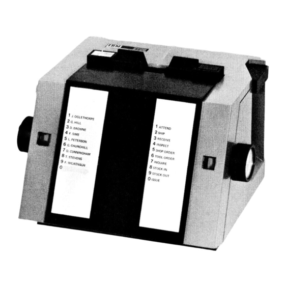
1800/2790 Adapter may be used as the system controller of plant operations is increasing. The IBM 2790 Data Com- for the 2790 system. For further information about the | munication System (Figure 1) is a two-way data communi... -
Page 6: Typical A P P Lic A T Io N S
3. The 2790 system has the ability to control a large Some of the applications of the 2790 system are: number of devices (up to 100 area stations, 1024 data... -
Page 7: Attendance Recording
DEU. Ten columns of numeric data together with variable fields are transmitted The IBM 2790 system may be configured in two ways for to the data processing system, updating the parts inventory. attendance recording. Where high-rate attendance recording... -
Page 9: Data Entry Units
2795 D A T A E N T R Y U N IT in the equivalent positions (Figure 5) of an identification The 2795 DEU includes the following features. badge. Entry Flag Carcf/Badge Slot Error Indicator/Reset Button Phone Jack Entry Request Lever Figure 3. IBM 2795 Data Entry Unit Data Entry Units... -
Page 10: 2795 Data Entry
Note: Detailed information about the badges used for A 10-position rotary switch is located on each side of the the 2790 system is given in the Systems Reference DEU frame. These switches are capable of transmitting numeric digits 0 through 9 to indicate such things as Library Manual, 357/1030/2790 Badge Specifications, GA21-9028. -
Page 11: Phone Jack
Reading Order 013 Badge Registration Punches Punch Columns Data (Data Shown Reads 0123456789) Corresponding Card Rows Registration Punches Data Punches (Data Shown Reads 1 234567899) ♦ Insert Column 80 End of Card with Face to Operator Registration Punches Data Punches (Data Shown Reads 9987654321) from Operator •... -
Page 12: Request L E V E R
Transaction Header (8 Bytes) Transaction Area Tens Units Tens Units Transaction Device List Number Station Length Address Address Hours Hours Minutes Minutes -------------------- > Binary Time-of-Day in EBCDIC * Left-hand rotary switch setting is referenced to the user transaction tables, and the transaction list number from the table is placed in byte 2 of the header. -
Page 13: 2796 Data Entry
Transaction Header (8 Bytes) Transaction Area Tens Units Tens Units Transaction Device List Number Station Length Address Address Hours Hours Minutes Minutes ..m m s Binary Time-of-Day (EBCDIC) * Upper left-hand rotary switch references a transaction from the user's transaction table. The transaction list number from the table is placed in byte 2 of the header. -
Page 14: Transaction Expansion
Transaction expansion is activated when the programmer defines the transaction codes in the transaction group (TGROUP) macro. See IBM System/360 Operating System, Transaction Expansion Basic Telecommunications Access Method, GC30-2004; or The DEU transaction selection may be expanded beyond IBM System/360 Disk Operating System, Basic Telecommu... -
Page 15: Area Stations
Two types of area stations, the IBM 2791 ration. and IBM 2793, are available: Area Station Nomenclature IBM2791 IBM 2793 Commonly used words with a specific meaning for the 2790 (Model 1 and Model 2) system are: 1000-foot cable trans 1000-foot cable trans mission capability mission capability Data Entry. -
Page 16: Transmission Capability
(TGROUP) macro. See IBM System /360 Operating by the operator, and other control conditions. System, Basic Telecommunications Access Method, GC30-2004;... -
Page 17: Card Reader
20 characters per second per channel. Card-reading rate is approximately 60 characters per second. The lower-speed channels are used to send data to IBM 1053 Cards are inserted in the card receiver, face up, column-one Printers. The higher-speed channels are used for all 2790 end first. -
Page 18: Transaction Selection Switches
EBCDIC EBCDIC Character Card Punch 0123 4567 Hexadecimal Character Card Punch 0123 4567 Hexadecimal 12-11-1 1001 0001 1 2 -1 1 1 0 0 000 1 12-11-2 1001 0010 1 2 - 2 1 1 0 0 0 0 1 0 12-3 12-11-3 1001 0011... -
Page 19: Manual Entry
Enter Key (EN TR) TRANSACTION SELECTION SWITCHES The Enter key enters the data that was keyed via the manual keyboard into the system as a data entry. CUSTOMER OPERATOR TRANSACTION GUIDANCE NOMENCLATURE NOMENCLATURE Clear Key ATTENDANCE The Clear key clears an unaccepted data entry from the BADGE WORKSHOP area station, extinguishes the Error lamp, releases the... -
Page 20: Area Station Addresses
3. System controller available to receive data. to select any one of the 32 possible data entry units re Note: If the 2715 system controller is in a “stop 2790 quiring service. The adapter services the devices on a input” status, but available for write operations to the blocking basis—... -
Page 21: 2793 Area S T A T Io N
2793 are: three 2795/2796 Attachment Additional features area station. Up to ten decimal digits may be read from (for a total of 32 data entry units) and an IBM 1053 Printer the OEM device under control of the operator guidance attachment. - Page 22 SAMPLE SPACE SPACE INSERT INSERT INSERT ALLOCATED TYPED ALLOCATED BLUE CARD BLUE CARD CARD FOR WORDS WORDS FOR WORDS JO B ASSIGN A S S IG N 2791 ENTER ENTER ENTER ENTER ENTER AREA DEPT. N O . QUAN TITY DEPT.
- Page 23 Transaction Header (8 Bytes) Byte Device Area Transaction Tens Units Units Tens Transaction Address List Number Station Length (First Address Hours Minutes Hours Minutes Device) " V Time-of-Day in EBCDIC Binary The Transaction Selection Switch position is referenced to the user transaction table.
- Page 24 1 1 1 01 0 0 1 E9 Figure 15. Loop Attachment and Shift Register Requires Typewriter Element P/N 1167998 - Feature ^9592 ** Idle character is not valid for 1053 printer. Figure 14. IBM 1053 and 2740 Printer Character Set Figure 16. IBM2793 Area Station...
-
Page 25: Ibm 2715 Transmission Control Unit
2790 terminals. Data assembled • Provides controls to read from and write on 2790 from 2790 terminals may be routed on a priority basis to terminals. System/360 when the 2715 is operating in the on-line mode, •... -
Page 26: Models Of Operation With System/360
On-Line/Off-Line. In this mode, the 2715 TCU collects data direct-access storage devices. The disk cartridge can be from 2790 terminals and stores the data on its integral disk. replaced to update the 2715 microcoded control program On a scheduled basis System/360 requests the stored data to new engineering change levels, or to provide feature from the 2715 TCU. -
Page 27: 2715 Machine Features
In item d above, the 1053 Printer address may be implicit or explicit. (For example, if the address • 64 IBM 2791 Area Stations with no data entry units. is supplied with the first data entry entered at the origina... -
Page 28: Selective Features For 2715 Model 1
I another bid), and discards the partial message entered. | 2715 Model 2 and a recommended optional feature for the 2715 Model 1. This feature permits attaching an IBM 2740 Communication Terminal Model 1 within 40 wire feet of System/360 to 2740. System/360-to-2740 transactions the 2715. - Page 29 2715-to-2740 Control Messages. For control between the (X‘D9’). The address data is the hexadecimal representatior 2715 and the 2740, the user may specify 2740 transaction | of the first core position to print out. The byte count is the IBM 2715 Transmission Control Unit...
-
Page 30: Selective Features For 2715 Model 2
2715 is command-free. If it is not command- IBM 3977 Model 1 and 2 free, it will signal ‘busy’ as status response to initial Model 1-600 bps and 1200 bps on leased facilities selection and the 2715 will not go to the neutral Model 2—... -
Page 31: Configuration Parameters
Sense Bits N ot Used. The 2715 does not use the following sense bits used in the 2701: • Normal/Expanded Capability Intervention Required • Time Out (for Stop 2790 Input) Data Check • Area Station Error Threshold Overrun These conditions cannot occur in the 2715; therefore, these 2715 G E N E R A L C H A R A C T E R IS T IC S bits are not used. -
Page 32: Commands
Test I/O Start I/O Execution of Start I/O causes initial selection and transfer | The 2715 responds to a Test I/O command with the follow of a command byte to the 2715. Command chaining is ing: treated as if it resulted from Start I/O. 1. -
Page 33: Binary Synchronous Communications Adapter
NAK in case of incorrect trans mission. Upon receiving a NAK indication, the master will *600 bps is for World Trade modems only. **Multipoint operation requires Expanded Capability feature. repeat transmission of the same message until successful IBM 2715 Transmission Control Unit... - Page 34 If assigned as an answering station, the 2715 can operate Multipoint-Selection in either manual or auto-answer mode, depending on the System/360 Sends - EOT A ENQ, DLE STX— text— DLE ETX- data-set hookup. When the 2715 is an answering station and its data set receives a signal, the 2715 monitors for an identi...
-
Page 35: Real-Time Clock (R Tc )
EOT before the end of the 20-second timeout, the correction pulses. 2715 responds with EOT (assuming it has no need to bid Interface information is provided in the IBM 2790 In for the line) and restarts the 20-second timeout. This con stallation Manual-Physical Planning, GA27-3017. - Page 36 • • • • • • • • • • • • • • • • • • l o o 9 « l » e o oi#i# • • • • ! • #1# # # • • • • • ! • • • O IO O O 0 0 O O • © • • # •...
- Page 37 2740 intervention required (power off, out X‘0089’— Basic Configuration. On the basic 2715, this panel shows of paper, or wrong mode). the status of the 2790 loop in indicator lights. Disk hard-status error. X‘008A’— X‘008B’— Disk seek failure. Line Transfer Switch Configuration. If the 2715 has a Line Disk timeout.
- Page 38 . 04 . 05 . 06 . 08 . 2 5 . 3 .6 . 7 . 8 . 9 1.0 2.5 3 7 8 9 10 25 30 50 60 70 80 90100 Entries Per Second...
-
Page 39: 2790 A D A P T E R
The following set of formulas provides a method of comput Keyboard Entries from 2791 Keyboard ing the peak use of the 2790 transmission line for a given % Utilization (2791 K) = 1.41 x entries/second data traffic. Figure 23 shows some of the formulas in chart form. -
Page 40: 2715 Operational Characteristics
• Byte count was exceeded. second to 12.6 badges per second. Total clockout time for • Stop (2790 input) was executed and transac 5400 employees increases to 7.1 minutes if the card rate of tion was not completed in the time allowed. -
Page 41: Data Format
2715 until both control of the user program if he wishes. ‘stop 2790 input’ and ‘set read deferred data mode’ have When rerouting transactions, the user should be careful been executed and the positive response to ‘set read defer... - Page 42 sage header, 5 bytes; transaction header(s), bytes; and A System/360 to 2715 transaction may contain up to 126 text. The message-header format is defined as follows: bytes, including an eight-byte header that must be provided by the System/360 problem program. The transaction head First, Second, and Third Byte—...
-
Page 43: 2715 Control Requests
Message Header Byte 1053 Data Message = Hex 01 Message Message 2740 Data Message = Hex 04 Length Control 2715 Control Message = Hex 02 Transaction Header Byte The second, third, and fourth bytes of the transaction header, which are in binary form, print out in hexadecimal notation as six digits, followed by a space. - Page 44 System/360 whenever a panel operator request causes the X‘FD’. The first data byte (r j) denotes the reason for 2790 system to be reconfigured (e.g., ‘bypass AS’ initiated the message. The X‘FD’ messages are: by panel request).
- Page 45 Control Requests 2. rj = X‘F2’ — The 2715 has detected that less than . r j = X‘F 1 ’ — The 2715 has performed a 2790 ERP 64 disk sectors remain available for data. The 2715 (Error Recovery Procedure) automatically. The rest sends the X‘FD’...
- Page 46 The steps in accomplishing this are: The response message is printed on the 2740 (if pre sent) prior to being sent to the CPU. a. If the 2790 input is active, the actions of the ‘stop 2790 input’ (X‘C ’) are performed (record stop, •...
- Page 47 = restored). Panel Responses. Any valid panel request that affects the = Blank (X‘40’). status of the 2790 system (i.e., C3, C4, or C l) automat rg, Tg = Status of segment A : ically causes a response message to be sent to System/360.
- Page 48 Note that the response indicates that the 2715 is completely devoid of all-data. a. If the 2790 input is active, the loop is brought to a record stop. A 3-second timeout is performed. b. The designated segment is restored.
- Page 49 Note: A negative response results in altering the user • Request Format tables in the 2715 core. A successful ‘user table load’ or an ICPL must be done prior to starting the 2790 input. System/360 and Panel— Standard with no additional data required.
- Page 50 System/360 Note: These messages are routed to the System/360 after a 2790 system or 2715 hard failure, or stop, has for console printout only if no 2740 is available for occurred.
- Page 51 S/360 2715 • Response Format 1. Set Read deferred data mode X 'C 5 '------- ► Execute 2. (a) Stop 2790 Input X 'C ó '----------------- ► Stop Loop (b) Read Data ^ — ..Send Data The response is a line of hexadecimal characters printed 3.
- Page 52 Enter X T ’ and the three-hex-digit work day numbers. made at least once after an ICPL to enable time to be No data checking is performed. sent to the 2790 system c. Press the Panel Request pushbutton. • Response Format •...
-
Page 53: 2790 Er P Message Format
• Function-Prevents loss of data when the 2715 is taken off-line. This request must be preceded by a = X ‘F1’ ‘stop 2790 input’ request, and, if the 2715 is a Model 1, = X‘40’ (blank) the Active/Inactive switch must be placed in the = X‘F1’-T he 2790 adapter error was de... -
Page 54: Restart-Number Logging
CPU. These numbers are intended to inexperienced operator, the sort will also proceed more allow data recovery when either the 2790 system hard stops slowly, as this causes the sort file to become larger and or the user program has checkpoint/restart capability. - Page 55 3000 characters per second. This means that the results, the on-line operation for data recovering should be channel can handle all data from the 2790 adapter, assuming scheduled at a low-traffic period. . adequate data service is provided by System/360. In addi...
-
Page 57: Error Procedures
Error Procedures The 2790 Data Communication System involves a large num Note: The 2790 system reliability assumes that a non ber of operators. Therefore, operator errors as well as trans blank character length count check is performed by mission errors must be considered. -
Page 58: Digit Check
Each single error is placed in the error buffer as a four- In addition to the preceding, the 2715 performs the following byte error record. This error record consists of a one- or error checks on data received from the 2790 transmission two-byte address followed by status information detailing line: the error. -
Page 59: 2715 Diagnostics
‘bi-sync block cancel’, upon which a retry is initiated. Data Flow and Storage Channel Adapter BSC Adapter Disk Adapter 2790 Adapter 2740 Adapter Microcode-Detected Errors Checking is implemented at critical points within the adapter Device Tests microcode. The purpose of this checking is to prevent loss The 2715 device test routines isolate functional and hard... -
Page 61: Programming Considerations
For The 2790 provides the user with a flexible communication detailed programming information, see Systems Reference and information system. To achieve this, the user provides... -
Page 62: User Job Planning F O R M S
Figures 32 through 34 are forms designed to aid the user DEULIST. The DEULIST (data entry unit list) macro is plan a 2790 system program. The forms are designed to be used to define one step of a transaction list for a data used as master copies for copying on office copy equipment. - Page 63 TR List Table * ri T G Table AS Table d 3 * c List List 2 List 4 List 3 List 1 TG 2 List List 2 Step 2 Step 3 ■ Step 1 —^ —___ ___________ Step 16 List 5 List 5 List T G 2...
-
Page 64: Transaction Group Table (Figure 33)
Number of Data Entry Units A ttached 1053 Printer Enter the number of data entry units that the area station If the transaction is to be printed at an area station, several is equipped to attach; permissible numbers are 8, 16,24, choices are available: or 32. - Page 65 is the terminal ID or Monitor key data. See Figure 35 to determine the proper column number to be checked.) Digit Value. Enter the value of the digit found in the Position column. The digit value may be 0 through 9. Guidance.
- Page 66 Area Station and Data Entry Unit Table Area Station Number Transaction Identification Group Name DEU's Comments Attached Data 8 ,1 6 ,2 4 ,3 2 Nos. Area Location Entry 00-99 Station Units • Figure 32. AS and DEU Table Form...
- Page 67 • Figure 33. Transaction Group Table Form Programming Considerations...
- Page 68 Transaction List Table Length Input Digit Route 1053 Printer Device Check Check Trans. Transaction List Message Transaction Group Number Text Name Name List Number (From Figure 32) Badge Card Manual 1-8 Char. 1-8 Char. 00-99 0-127 A or D BCMO 1-31 1-81 1-31...
- Page 69 2795 Data Entry as Assembled in the 2715 TCU (12 EBCDIC Digits) Card or Badge Columns Right- Code Hand Rotary Switch 2796 DataEntry as Assembled in the 2715 TCU (18 EBCDIC Digits) Digit Card or Bad Ige Columns Upper Monitor Right Rotary (1 ,2 , or 3)
-
Page 71: Glossary
Glossary ACK: Line control character for positive acknowledgment. ENQ: Line-control character, “enquiry.” AS: Area Station; AS is also the mnemonic for the macro EOC: End of card. that defines the Area Station for the System/360 assembler EREP: Environment Record Edit and Print program. - Page 72 TGROUP: Mnemonic for a System/360 assembler macro User Transaction Tables: Program tables that define the instruction. parameters and controls for the 2790 system. DOS and OS/360 Assembler Language macros are provided to define Time Stamp: A four-byte field that contains the value of user tables for the 2715.
-
Page 73: In D Ex
2790 input badge reader address scan area station/adapter errors badge reading on 1035 send partial error log badge reading on 2791 set dual communications switch... - Page 74 I/O bus-out check hardware tests IBM 3976 Model 3 modem digit check IBM 3977 Models 1 and 2 modem digital device read-in ICPL switch digital device read-in address identification card punching digital device read-in data entry In Process indicator...
- Page 75 Release key modems request formats (standard) German PTT Reserve/Release commands IBM 3976 Model 3 reset dual communications switch IBM 3977 Models 1 and 2 reset read deferred data mode Japanese NTT Reset switch Swedish PTT reset two-processor switch United Kingdom GPO...
- Page 76 2740-1 operating procedure transaction selection switches 2740-1 timeout transaction time stamp 2790 adapter transmission line utilization chart 2790 ERP message format TRUST macro 6 1 ,1 9 2791 Area Station Two Processor Switch feature operator panel data entry...
- Page 77 Transaction nomenclature to be within this space and centered about the two center lines for each transaction Nomenclature for each guidance light is to be within appropriate box. Select Transaction Release Repeat/ Card In C le a r Line Process Card Reader...
- Page 78 ♦...
- Page 79 Transaction nomenclature to be within this space and centered about the two center lines for each transaction Nomenclature for each guidance light is to be within appropriate box. Select Transaction Release Repeat/ Card In Line C le a r Process Card Reader...
- Page 81 Transaction nomenclature to be within this space and centered about the two center lines for each transaction Nomenclature for each guidance light is to be within appropriate box. Select Transaction Release Repeat/ Card In Line C le a r Process Card Reader...
- Page 83 Transaction nomenclature to be within this space and centered about the two center lines for each transaction Nomenclature for each guidance light is to be within appropriate box. Select Transaction Release Repeat/ Card In Line C lea r Process Card Reader...
- Page 86 GA27-3015-1 " J > > International Business Machines Corporation Data Processing Division 112 East Post Road, White Plains, N.Y. 10601 [USA Only] IBM World Trade Corporation 821 United Nations Plaza, New York, New York 10017 [International]...
- Page 87 R EA D ER 'S COMMENT FORM GA27-3015-1 Component Description: IBM 2790 Data Communication System • How did you use this publication? □ As a reference source □ classroom text As a □ As a self-study text • Based on your own experience, rate this publication .
- Page 88 All comments and suggestions become the property of IBM. Please note: Requests for copies of publications and for assistance in using your IBM system should be directed to your IBM representative or to the IBM sales office serving your locality.