
Related Manuals for AXIOMTEK IMB540


Summary of Contents for AXIOMTEK IMB540
- Page 1 IMB540 ® Intel Socket 1700 Core i9/i7/ i5/ i3 ® ® /Pentium / Celeron and Xeon® E Processors ATX Industrial Motherboard User’s Manual...
-
Page 2: Disclaimers
Axiomtek does not make any commitment to update the information in this manual. Axiomtek reserves the right to change or revise this document and/or product at any time without notice. No part of this document may be reproduced, stored in a retrieval system, or transmitted, in any form or by any means, electronic, mechanical, photocopying, recording, or otherwise, without the prior written permission of Axiomtek Co., Ltd. -
Page 3: Esd Precautions
To discharge static electricity from your body. ◼ Wear a grounding wrist strap, available from most electronic component stores, when handling boards and components. Trademarks Acknowledgments Axiomtek is a trademark of Axiomtek Co., Ltd. ® ® Intel and Celeron are trademarks of Intel Corporation. -
Page 4: Table Of Contents
Table of Contents Disclaimers ...................... ii ESD Precautions ..................... iii Section 1 Introduction ..........1 Features ....................2 Specifications ..................2 Packing list .................... 4 Section 2 Board and Pin Assignments ....5 Board Layout ..................5 Block Diagram ..................6 Jumper Settings .................. - Page 5 Section 4 AMI BIOS Setup Utility ......23 Starting ....................23 Navigation Keys .................. 23 Main Menu ..................25 Advanced Menu .................. 26 Chipset Menu ..................39 Security Menu ..................47 Boot Menu ................... 48 Save & Exit Menu ................49 Appendix A TPM Module Installation ......
- Page 6 This page is intentionally left blank.
-
Page 7: Introduction
Section 1 Introduction The IMB540 is an advanced ATX industrial motherboard based on the 12th Generation Intel® Core™ i9 / i7/ i5/ i3/ Pentium®, Celeron® processors (Alder lake S) in an LGA1700 socket and comes with an Intel® R680E chipset. Specially designed for optimal computing and visual performance, the IMB540 motherboard is an ideal solution for major industry applications ranging from financial modeling to designing complex buildings and vehicles. -
Page 8: Features
IMB540 User’s manual Features LGA1700 socket 12th Generation Intel® Core™ i9 / i7/ i5/ i3/ Pentium®, Celeron® ⚫ processors (Alder lake S) up to 125W ⚫ 4 x 288-pin DDR4-3200 ECC/non-ECC un-buffered Long-DIMM with maximum memory capacity up to 128GB (max. 32GB per slot) ⚫... - Page 9 IMB540 User’s manual ⚫ USB Interface ◼ 4 x USB3.2 Gen2x1 (10Gbps) ports.(rear I/O) ◼ 2 x Dual USB 3.2 Gen1 (5Gbps) ports. (internal,box header) ◼ 4 x USB 2.0 ports. (internal,pin header) ◼ 1 x USB 2.0 ports. (internal x 180D type A) ⚫...
-
Page 10: Packing List
IMB540 User’s manual Packing list Bulk packing ⚫ ◼ 1 x Motherboard ◼ 1 x I/O bracket Gift box ⚫ 1 x Motherboard ◼ 1 x I/O bracket ◼ Introduction... -
Page 11: Board And Pin Assignments
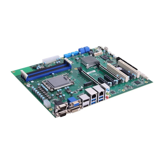
IMB540 User’s manual Section 2 Board and Pin Assignments Board Layout Top side Board and Pin Assignments... -
Page 12: Block Diagram
IMB540 User’s manual Block Diagram Board and Pin Assignments... -
Page 13: Jumper Settings
A square pad, which you can find on the back of the motherboard, is ⚫ usually used for pin 1. Before applying power to the IMB540 series , make sure all of the jumpers are in motherboard factory default position. Below you can find a summary table of all jumpers and onboard default settings. -
Page 14: Pcie X16 Slot Bifurcation (Jp1)
IMB540 User’s manual 2.3.1 PCIe x16 slot bifurcation (JP1) Use these jumpers (3x1-pin p=2.54mm) to set signal of PCIe x16 slot. CN14 PCIe 1 x16 PCIe 4 x0 (Default) PCIe 1 x8 PCIe 4 x8 2.3.2 AT/ATX Mode Select (JP3) This 3x1-pin p=2.54mm jumper allows you to select AT or ATX power mode. - Page 15 IMB540 User’s manual Signals go to other parts of the system through connectors. Loose or improper connection might cause problems. Make sure all connectors are properly and firmly connected. Here is a summary table showing the connectors on the motherboard.
-
Page 16: Com1 Connector (Cn1)
IMB540 User’s manual 2.3.4 COM1 Connector (CN1) This is a high rise 9-pin D-Sub connector for COM1 serial port interface. The pin assignments of RS-232/422/485 are listed in the table below. RS-232 RS-422 RS-485 DCD# 485- 485+ DTR# DSR# RTS# CTS# : Signals of COM1, COM2 can be RS-232/422/485 by BIOS setting. -
Page 17: Vga And Dvi-D Connector (Cn3)
IMB540 User’s manual 2.3.6 VGA and DVI-D Connector (CN3) CN3 is a double-deck connector comprising a lower connector for DVI-D port and an upper connector for VGA port. The high rise DVI-D connector provides transmission of fast and high quality video signals between a source device (graphic card) and a display device (monitor). -
Page 18: Lan And Usb 3.2 Connectors (Cn5 And Cn6)
IMB540 User’s manual 2.3.8 LAN and USB 3.2 Connectors (CN5 and CN6) The motherboard comes with two high performance plug and play Ethernet interfaces (RJ-45) which are fully compliant with the IEEE 802.3 standard. Connection can be established by plugging one end of the Ethernet cable into this RJ-45 connector and the other end to a (LAN2/CN5)1000/100/10 (LAN1/CN6)2500/1000/100/10 Base-T hub. -
Page 19: Gpio Header (Cn7)
IMB540 User’s manual 2.3.9 GPIO Header (CN7) This header (5x2-pin p=2.00mm) is for digital I/O interface. Signal Signal DIO1 DIO8 DIO2 DIO7 DIO3 DIO6 DIO4 DIO5 The default value of DIO1 to DIO8 is set as GPI with high level. -
Page 20: 2280 Key M Nvme Ssd (Cn10)
IMB540 User’s manual 2.3.12 M.2 2280 Key M NVMe SSD (CN10) The CN10 (5x1-pin p=2.00mm) is for SMBus (System Management Bus) interface. Signal Signal Signal Signal +3.3V +3.3V PERn3 PERp3 LED_1# PETn3 +3.3V PETp3 +3.3V +3.3V PERn2 +3.3V PERp2 PETn2... -
Page 21: Internal Usb Headers (Cn13, Cn15)
IMB540 User’s manual 2.3.14 Internal USB Headers (CN13, CN15) These are 5x2-pin p=2.54mm headers for USB 2.0 interface. Signal Signal +5 V_DUAL +5 V_DUAL USB - USB - USB + USB + 2.3.15 PCI-Express Mini Card Connector (CN16) The CN16 complies with PCI-Express Mini Card Spec. V1.2. -
Page 22: Tpm Pin Header (Cn19)
IMB540 User’s manual 2.3.16 TPM Pin Header (CN19) These are 7x2-pin p=2.0mm headers for SPI interface with an AX93515 TPM module. Signal Signal VCC3P3 MOSI MISO PIRQ 12 10 The screw type is M2*0.4. Note 2.3.17 Front Panel Header (CN17) This is a front panel header (7x2-pin p=2.54mm). -
Page 23: Power Input Connectors (Atx1 And Cn18)
IMB540 User’s manual 2.3.18 Power Input Connectors (ATX1 and CN18) Steady and sufficient power can be supplied to all components on the motherboard by connecting the power connector. Please make sure all components and devices are properly installed before connecting the power connector. -
Page 24: Com Headers (Com3, Com4, Com5, Com6)
IMB540 User’s manual 2.3.20 COM Headers (COM3, COM4, COM5, COM6) The motherboard comes with 5x2-pin p=2.54mm headers for COM serial port interfaces. COM3, COM4, COM5, COM6: Signal Signal DCD# DSR# RXD# RTS# TXD# CTS# DTR# 2.3.21 Fan Connectors (FAN1, FAN2, FAN3) This motherboard has three fan connectors. -
Page 25: Pci-Express X4 Slots (Pcie2, Pcie3, Pcie5)
IMB540 User’s manual 2.3.22 PCI-Express x4 Slots (PCIe2, PCIe3, PCIe5) This motherboard has three PCI-Express x4 slots Signal Signal +12V_PS +12V_PS +12V_PS +12V_PS +12V_PS SMB_CLK_RESUME SMB_DATA_RESUME +3.3V_PS +3.3V_PS +3.3V_SB +3.3V_PS PCH_WAKE_N PWRGD CLKOUT_PCIE_P5 PCIE1_SLOT1_TX_DP_C CLKOUT_PCIE_N5 PCIE1_SLOT1_TX_DN_C PCIE1_SLOT1_RX_DP_C PCIEX4_SLOT1_PRSNT2_N PCIE1_SLOT1_RX_DN_C PCIE2_TX_DP... -
Page 26: Sata 3.0 Connectors (Sata1 , Sata2)
IMB540 User’s manual 2.3.23 SATA 3.0 Connectors (SATA1 , SATA2) These Serial Advanced Technology Attachment (Serial ATA or SATA) connectors are for SATA 3.0 interface allowing up to 6.0Gb/s data transfer rate. It is a computer bus interface for connecting to devices such as hard disk drive. -
Page 27: Hardware Description
The IMB540 series uses AMI Plug and Play BIOS. System Memory The IMB540 supports four 288-pin DDR4 DIMM sockets for maximum memory capacity up to 128GB DDR4 SDRAMs. The memory module comes in sizes of 2GB, 4GB, 8GB, 16GB and 32GB. - Page 28 IMB540 User’s manual This page is intentionally left blank. Hardware Description...
-
Page 29: Ami Bios Setup Utility
IMB540 User’s manual Section 4 AMI BIOS Setup Utility The AMI UEFI BIOS provides users with a built-in setup program to modify basic system configuration. All configured parameters are stored in a flash chip to save the setup information whenever the power is turned off. This chapter provides users with detailed description about how to set up basic system configuration through the AMI BIOS setup utility. - Page 30 IMB540 User’s manual Hot Keys Description → Left/Right The Left and Right <Arrow> keys allow you to select a setup screen. The Up and Down <Arrow> keys allow you to select a setup screen or sub Up/Down screen. The <Enter> key allows you to display or change the setup option listed for a Enter particular setup item.
-
Page 31: Main Menu
IMB540 User’s manual Main Menu When you first enter the setup utility, you will enter the Main setup screen. You can always return to the Main setup screen by selecting the Main tab. System Time/Date can be set up as described below. -
Page 32: Advanced Menu
IMB540 User’s manual Advanced Menu The Advanced menu also allows users to set configuration of the CPU and other system devices. You can select any of the items in the left frame of the screen to go to the sub menus: ►... - Page 33 IMB540 User’s manual ⚫ Trusted Computing Enable or disable security device support. AMI BIOS Setup Utility...
- Page 34 IMB540 User’s manual ⚫ Platform Misc Configuration This screen allows you to set Platform Misc Configuration. Native PCIE Enable Bit - PCIe Native * control\n 0 - ~ Hot Plug\n 1 - SHPC Native Hot Plug control\n 2 - ~ Power Management Events\n 3 - PCIe Advanced Error Reporting control\n 4 - PCIe Capability Structure control\n 5 - Latency Tolerance Reporting control.
- Page 35 IMB540 User’s manual ⚫ CPU Configuration This screen shows CPU information, and you can change the value of the selected option. Hardware Prefetcher Turn on/off the MLC streamer prefetcher. Adjacent Cache Line Prefetch Turn on/off prefetching of adjacent cache lines.
- Page 36 IMB540 User’s manual Enable / Disable AES (Advanced Encryption Standard) Boot performance mode Select the performance mode that the BIOS will run after the reset. Intel (R) SpeedStep(tm) Allows more than two frequency ranges to be supported. Turbo Mode Allows to enable processor cores to raise the operating frequency.
- Page 37 IMB540 User’s manual ⚫ SATA Configuration During system boot up, the BIOS automatically detects the presence of SATA devices. In the SATA Configuration menu, you can see the hardware currently installed in the SATA ports. SATA Controller(s) Enable or disable the SATA Controller feature. The default is Enabled.
- Page 38 IMB540 User’s manual ⚫ NVMe Configuration This screen shows NVMe device information. ⚫ AMT Configuration This screen displays Active Management Technology information. AMI BIOS Setup Utility...
- Page 39 IMB540 User’s manual AMT BIOS Features Enable or disable Active Management Technology BIOS features. The default is Enabled. ⚫ F81966 Super IO Configuration You can use this screen to select options for the Super IO Configuration, and change the value of the selected option. A description of the selected item appears on the right side of the screen.
- Page 40 IMB540 User’s manual ⚫ Serial Port 1 Configuration Use these items to set parameters related to serial port 1 and 2. Serial Port 1 This tiem allows you to use it as RS232/422/485. The default is RS232. Serial Port 2 This tiem allows you to use it as RS232/422/485.
- Page 41 IMB540 User’s manual ⚫ Hardware Monitor This screen monitors hardware health status. This screen displays the temperature of system and CPU, cooling fans speed in RPM and system voltages (VCC_CPU, DDR, +12V, +5V and +3.3V). CPU FAN = FAN1; SYS FA = FAN2; AUX FAN = FAN3 .
- Page 42 IMB540 User’s manual ⚫ USB Configuration This screen shows USB configuration. AMI BIOS Setup Utility...
- Page 43 IMB540 User’s manual ⚫ PCI Subsystem Settings This screen allows you to set PCI Subsystem mode. PCI Latency Timer Set the value to be programmed into PCI Latency Timer Register. VGA Palette Snoop Enables or Disables VGA Palette Registers Snooping.
- Page 44 IMB540 User’s manual ⚫ Compatibility Support Module (CSM) Configuration This screen displays CSM information. CSM Support Enabled / Disable CSM Support. GateA20 Active UPON REQUEST - GA20 can be disabled using BIOS services. ALWAYS - do not allow to disable GA20. This option is useful when any RT code is executed above 1MB.
-
Page 45: Chipset Menu
IMB540 User’s manual Chipset Menu The Chipset menu allows users to change the advanced chipset settings. You can select any of the items in the left frame of the screen to go to the sub menus: ► System Agent (SA) Configuration ►... - Page 46 IMB540 User’s manual ⚫ System Agent (SA) Configuration This screen allows users to configure System Agent (SA) parameters. For items marked with “”, please press <Enter> for more options. VT-d Check to enable VT-d function on MCH. Above 4GB MMIO BIOS assignment Enable/Disable above 4GB Memory Mapped IO BIOS assignment \n\n.
- Page 47 IMB540 User’s manual ⚫ Graphics Configuration This screen shows graphics configuration. Internal Graphics Keep IGFX enabled based on the setup options. AMI BIOS Setup Utility...
- Page 48 IMB540 User’s manual ⚫ CPU PCI Express Root Port This screen shows CPU PCI Express root port information. ASPM Set the ASPM Level:\nForce L0s - Force all links to L0s State\nForce L1 - Force all links to L1 State\nForce L0sL1 - Force all links to L0SL1 State\nDISABLE - Disables ASPM.
- Page 49 IMB540 User’s manual ⚫ PCH-IO Configuration This screen allows you to set PCH parameters. PCI Express Configuration Configure PCIe Speed. HD Audio Configuration Enable or disable HD Audio. Wake on LAN Enable Enable or disable integrated LAN to wake the system.
- Page 50 IMB540 User’s manual ⚫ PCI Express Configuration This screen shows PCI Express configuration. PCIE 1 -> PCIE5 PCIE 21-> PCIE3 PCIE 25-> PCIE2 Note AMI BIOS Setup Utility...
- Page 51 IMB540 User’s manual PCIe Speed Configure PCIe Speed. ASPM Set the ASPM Level:\nForce L1 - Force all links to L1 State\nAUTO - BIOS auto configure\nDISABLE - Disables ASPM. Detect Non-Compliance Device Detect Non-Compliance PCI Express Device. If enabled, it will take more time at POST time.
- Page 52 IMB540 User’s manual ⚫ HD Audio Configuration This screen shows HD Audio information AMI BIOS Setup Utility...
-
Page 53: Security Menu
IMB540 User’s manual Security Menu The Security menu allows users to change the security settings for the system. ⚫ Administrator Password This item indicates whether an administrator password has been set (installed or uninstalled). ⚫ User Password This item indicates whether a user password has been set (installed or uninstalled). -
Page 54: Boot Menu
IMB540 User’s manual Boot Menu The Boot menu allows users to change boot options of the system. ⚫ Setup Prompt Timeout Number of seconds to wait for setup activation key. 65535(0xFFFF) means indefinite waiting. ⚫ Bootup NumLock State Use this item to select the power-on state for the keyboard NumLock. -
Page 55: Save & Exit Menu
IMB540 User’s manual Save & Exit Menu The Save & Exit menu allows users to load your system configuration with optimal or fail-safe default values. ⚫ Save Changes and Exit When you have completed the system configuration changes, select this option to leave Setup and return to Main Menu. - Page 56 IMB540 User’s manual ⚫ Save Changes When you have completed the system configuration changes, select this option to save changes. Select Save Changes from the Save & Exit menu and press <Enter>. Select Yes to save changes. ⚫ Discard Changes Select this option to quit Setup without making any permanent changes to the system configuration.
-
Page 57: Appendix Atpm Module Installation
The TPM 2.0 (Trusted Platform Module 2.0) module is a modularized design applying to the IMB540 and provides enhanced hardware security for the computer. In this appendix you will learn how to install the TPM 2.0 module into the IMB540. Please read and follow the instructions below carefully. - Page 58 IMB540 User’s manual (In the Trusted Computing section, on the first of line it will show “TPM2.0 Device Found”, if installation is successful.) b. In the Windows 10 OS environment, enter Device Manager, and selectSecurity devices. The screen will show “Trusted Platform Module 2.0” if installation is successful.
- Page 59 IMB540 User’s manual c. In the Windows 10 OS environment, enter Control Panel, select BitLocker Drive Encryption, and enter TPM Administration. The screen will show the information below if installation is successful. TPM Module Installation...
- Page 60 IMB540 User’s manual This page is intentionally left blank. TPM Module Installation...
-
Page 61: Appendix B Iamt Settings
IMB540 User’s manual Appendix B iAMT Settings The Intel ® Active Management Technology (Intel ® AMT) utilizes built-in platform capabilities and popular third-party management and security applications to allow IT administrators to remotely discover, repair and better protect their networked computing assets, thus significantly improving IT management efficiency. -
Page 62: Iamt Settings
IMB540 User’s manual iAMT Settings 1. Select Intel® AMT configuration and press <Enter>. 2. Select Network Setup to configure iAMT. iAMT Settings... - Page 63 IMB540 User’s manual 3. Go back to Intel ® AMT Configuration, then select Activate Network Access and press <Enter>. 4. Exit from MEBx after completing the iAMT settings. iAMT Settings...
-
Page 64: Iamt Web Console
IMB540 User’s manual iAMT Web Console On a web browser, type http://(IP ADDRESS):16992, which connects to iAMT Web. Example: http://10.1.40.214:16992 To log on, you will be required to type in your username and password for access to the Web. USER: admin (default) - Page 65 IMB540 User’s manual Enter the iAMT Web. Click Remote Control, and select commands on the right side. iAMT Settings...
- Page 66 IMB540 User’s manual When you have finished using the iAMT Web console, close the Web browser. iAMT Settings...
-
Page 67: Appendix C Digital I/O
IMB540 User’s manual Appendix C Digital I/O Digital I/O Software Programming ⚫ I2C to GPIO PCA9554PW GPIO[3:0] is Output, GPIO[7:4] is Input. I2C address: 0b0100100x. ⚫ IOBASE: 0xF040 ⚫ Registers: ⚫ Command byte Command Protocol Function Read byte Input port register... - Page 68 IMB540 User’s manual Register 1: Output port register. This register reflects the outgoing logic levels of the pins defined as outputs by Register 3. Bit values in this register have no effect on pins defined as inputs. Reads from this register return the value that is in the flip-flop controlling the output selection, not the actual pin value.