Table of Contents
Advertisement
Quick Links
Product User Manual
and enterprise branch and head offices
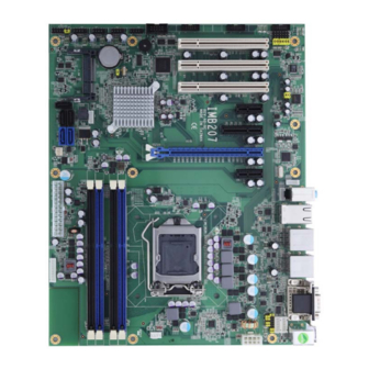
IMB207
www.enochsystems.com
1-877-722-1116
sales@enochsystems.com
Copyright © 2013 Enoch Systems, LLC, Enoch Systems and the Enoch Systems logo are trademarks or registered trademarks of Enoch Systems, LLC and/or its affiliates in the U.S. and other countries.
Third-party trademarks mentioned are the property of their respective owners. All rights reserved.
Advertisement
Table of Contents

Related Manuals for AXIOMTEK IMB207 Series


Summary of Contents for AXIOMTEK IMB207 Series
- Page 1 Product User Manual and enterprise branch and head offices IMB207 www.enochsystems.com 1-877-722-1116 sales@enochsystems.com Copyright © 2013 Enoch Systems, LLC, Enoch Systems and the Enoch Systems logo are trademarks or registered trademarks of Enoch Systems, LLC and/or its affiliates in the U.S. and other countries. Third-party trademarks mentioned are the property of their respective owners.
- Page 2 IMB207 Series ® Intel Socket 1155 Core i7 / Core ® i5 / Core i3 / Celeron Processor ATX Industrial Motherboard User’s Manual...
- Page 3 Axiomtek does not make any commitment to update the information in this manual. Axiomtek reserves the right to change or revise this document and/or product at any time without notice. No part of this document may be reproduced, stored in a retrieval system, or transmitted, in any form or by any means, electronic, mechanical, photocopying, recording, or otherwise, without the prior written permission of Axiomtek Co., Ltd.
-
Page 4: Esd Precautions
Wear a wrist-grounding strap, available from most electronic component stores, when handling boards and components. Trademarks Acknowledgments Axiomtek is a trademark of Axiomtek Co., Ltd. ® Windows is a trademark of Microsoft Corporation. AMI is a trademark of American Megatrend Inc. -
Page 5: Table Of Contents
Table of Contents Disclaimers ...................... ii ESD Precautions ..................... iii Chapter 1 Introduction ..........1 1.1 Features ....................1 1.2 Specifications ..................2 1.3 Utilities Supported ................. 3 Chapter 2 Board and Pin Assignments ....5 2.1 ... - Page 6 Chapter 3 Hardware Installation ......21 3.1 Installing the Processor ............... 21 3.2 Installing the Memory ................27 3.2.1 Dual Channel Memory Configuration ............27 Chapter 4 Hardware Description ......29 4.1 Microprocessors .................. 29 4.2 ...
- Page 7 ® Intel iAMT Web Console ................72 ...
-
Page 8: Chapter 1 Introduction
IMB207 LGA1155 ATX Motherboard Chapter 1 Introduction ® The IMB207 ATX industrial motherboard supports LGA1155 socket for Intel Core i7 / ® Core i5 / Core i3 / Celeron processors with 32/22nm technology .The board integrates ® Intel Q77 that delivers outstanding system performance through high-bandwidth interfaces, multiple I/O functions for interactive applications and various embedded computing solutions. -
Page 9: Specifications
IMB207 LGA1155 ATX Motherboard Specifications ® Intel Core i7 / Core i5 / Core i3 / Celeron ® processors. ® Supports Intel Turbo Boost Technology (see Note 1 below). System Chipset ® Intel Q77 chipset. ... -
Page 10: Utilities Supported
IMB207 LGA1155 ATX Motherboard Audio HD audio codec (Realtek ALC662) for line/speaker-out and MIC-in on the rear I/O triple-deck connector, with LM1877 audio amplifier. Supports jack-detection. Supports CD-in. Expansion Slot One PCI-Express x16 Gen. 3 (slot 2). ... - Page 11 IMB207 LGA1155 ATX Motherboard This page is intentionally left blank. Introduction...
-
Page 12: Board And Pin Assignments
IMB207 LGA1155 ATX Motherboard Chapter 2 Board and Pin Assignments Board Dimensions and Fixing Holes Top Side Board and Pin Assignments... -
Page 13: Board Layout
IMB207 LGA1155 ATX Motherboard Board Layout Top Side I/O Bracket Board and Pin Assignments... -
Page 14: Jumper Settings
And remove jumper clip from 2 jumper pins to open. The following illustration shows how to set up jumper. Before applying power to IMB207 Series, please make sure all of the jumpers are in factory default position. Below you can find a summary table of all jumpers and onboard default settings. -
Page 15: Audio Output Selection (Jp1)
IMB207 LGA1155 ATX Motherboard 2.3.1 Audio Output Selection (JP1) JP1 is for user to select line-out or speaker-out as source for audio output on CN5. When speaker-out is used, it delivers 2W/channel continuous into 8 Ohm loads. Function Setting Line out (Default) 1-3, 2-4 close Speaker out (w/ amplifier) 3-5, 4-6 close... -
Page 16: Com1 Data/Power Selection (Jp7)
IMB207 LGA1155 ATX Motherboard 2.3.5 COM1 Data/Power Selection (JP7) The COM1 port has +5V or +12V power capability on DCD and RI by setting this jumper. When COM1 is set to +5V or +12V, please make sure its communication mode is RS-232 (see section 2.3.6). -
Page 17: Connectors
IMB207 LGA1155 ATX Motherboard Connectors Signals go to other parts of the system through connectors. Loose or improper connection might cause problems, please make sure all connectors are properly and firmly connected. Here is a summary table which shows all connectors on the hardware. Connector Description CN1~2... -
Page 18: Displayport Connectors (Cn1 And Cn2)
IMB207 LGA1155 ATX Motherboard 2.4.1 DisplayPort Connectors (CN1 and CN2) DisplayPort is a digital display interface standard. This board has two DisplayPort interfaces which are available through connector CN1 and CN2. Signal LANE 0 CN1 and CN2 LANE 0# LANE 1 LANE 1# LANE 2 LANE 2#... -
Page 19: Ps/2 Keyboard And Mouse Connector (Cn4)
IMB207 LGA1155 ATX Motherboard CN3B Signal CN3B Signal TX2- TX2+ Ground DVI_SPD_CLK DVI_SPD DATA CRT-VSYNC TX1- TX1+ Ground VGAVCC Ground FPDETECT TX0- TX0+ Ground Ground TXC+ TXC- CRT-RED CRT-GREEN CRT-BLUE CRT-HSYNC VGAGND 2.4.3 PS/2 Keyboard and Mouse Connector (CN4) The board has two 6-pin mini-DIN PS/2 connectors; green for mouse and purple for keyboard. -
Page 20: Usb Port Stacks (Cn6 And Cn7)
IMB207 LGA1155 ATX Motherboard 2.4.5 USB Port Stacks (CN6 and CN7) These Universal Serial Bus (compliant with USB 3.0 (5Gb/s)) connectors on the rear I/O are for installing USB peripherals such as keyboard, mouse, scanner, etc. The CN6 carries USB port 2 and 3 signals while CN7 carries USB port 0 and 1 signals. Signal Signal USB_VCC (+5V... -
Page 21: Ethernet Ports (Cn9)
IMB207 LGA1155 ATX Motherboard 2.4.7 Ethernet Ports (CN9) The board is equipped with two high performance plug and play ethernet interfaces which are fully compliant with the IEEE 802.3 standard. The ethernet port uses RJ-45 connector. Connection can be established by plugging one end of the ethernet cable into this RJ-45 connector and the other end to a 1000/100/10-Base-T hub. -
Page 22: Internal Keyboard Connector (Cn13)
IMB207 LGA1155 ATX Motherboard 2.4.10 Internal Keyboard Connector (CN13) The internal keyboard interface is available through a 5-pin connector. Signal Keyboard Clock Keyboard Data +5V level 2.4.11 PCI and PCI-Express Slots (PCI1~3, CN14~16 and CN18) The PCI and PCI-Express slots support cards such as LAN card, SCSI card, USB card and other cards that comply with PCI specifications. -
Page 23: Usb Connectors (Cn21, Cn22, Cn23 And Cn25)
IMB207 LGA1155 ATX Motherboard 2.4.13 USB Connectors (CN21, CN22, CN23 and CN25) The CN21, CN22, CN23 and CN25 are interfaces carrying USB port 4 and 5, USB port 8 and 9, USB port 10 and 11 and USB port 6 and 7, respectively. They are for installing versatile USB 2.0 compliant peripherals. -
Page 24: Atx Power Connectors (Cn29 And Atx2)
IMB207 LGA1155 ATX Motherboard 2.4.16 ATX Power Connectors (CN29 and ATX2) Steady and sufficient power can be supplied to all components on the board by connecting power connector. Please make sure all components and devices are properly installed before connecting the power connector. External power supply plug fits into this connector in only one orientation. -
Page 25: Cfast™ Socket (Cf1)
IMB207 LGA1155 ATX Motherboard 2.4.18 CFast™ Socket (CF1) The board is equipped with a CFast socket to support CFast card which is based on the Serial ATA bus. The socket is specially designed to avoid incorrect installation of CFast card. When installing or removing CFast card, please make sure system power is off. -
Page 26: Front Panel Connector (Jp11)
IMB207 LGA1155 ATX Motherboard 2.4.20 Front Panel Connector (JP11) Signal PWRLED+ EXT SPK- Buzzer PWRLED- N.C. N.C. EXT SPK+ PWRSW- PWRSW+ HW RST- HW RST+ HDDLED- HDDLED+ Power LED Pin 1 connects anode(+) of LED and pin 5 connects cathode(-) of LED. The power LED lights up when the system is powered on. - Page 27 IMB207 LGA1155 ATX Motherboard This page is intentionally left blank. Board and Pin Assignments...
-
Page 28: Chapter 3 Hardware Installation
IMB207 LGA1155 ATX Motherboard Chapter 3 Hardware Installation ® Before installing the processor, please access Intel website for more detail information of Processor Integration Video (LGA1155): http://www.intel.com/support/tw/processors/sb/CS-030860.htm Installing the Processor The LGA1155 processor socket comes with a cover to protect the processor. Please install the processor into the CPU socket step by step as below: Step1 Opening the socket: Disengage load lever by releasing down and out on the hook. - Page 29 IMB207 LGA1155 ATX Motherboard Note: Vertical removal is NOT recommended, as it requires higher force and can lead to socket contact damage. Caution: Never touch fragile socket contacts to avoid damage and do not touch processor sensitive contacts at any time during installation. Step3 Processor installation: Lift processor package from shipping media by grasping the substrate edges.
- Page 30 IMB207 LGA1155 ATX Motherboard Grasp the processor with thumb and index finger along the top and bottom edges. (Do not touch the orientation notches.) The socket will have cutouts for your fingers to fit into (see image below). Carefully place the processor into the socket body vertically (see image below). ...
- Page 31 IMB207 LGA1155 ATX Motherboard Verify that package is within the socket body and properly connected to orientation keys. Close the socket (see image below): 1. Gently lower the load plate. 2. Make sure load plate's front edge slides under the shoulder screw cap as the lever is lowered.
- Page 32 IMB207 LGA1155 ATX Motherboard Screw the CPU cooling fan onto the board. Make sure the CPU fan is plugged to the CPU fan connector. Step5 Removing the processor: Open the socket: Disengage the load lever. Open the load plate Remove the Processor package, holding along the top and bottom edges, or by using a ...
- Page 33 IMB207 LGA1155 ATX Motherboard Assemble LGA1155 socket protective cover: Hold protective cover at 45 degree angle to the LGA1155 Socket. Carefully lower protective cover on hinge side first, to contact with the outside wall of the LGA1155 Socket: Engage protective cover retention features to outside of LGA1155 Socket, AND align 2 cover corners to socket corners (This step is critical to avoid Bent Contact Damage!).
-
Page 34: Installing The Memory
IMB207 LGA1155 ATX Motherboard Installing the Memory The board supports four 240-pin DDR3 DIMM memory sockets with maximum memory capacity up to 32GB. Note: A DDR3 module has the same physical dimensions as a DDR2 DIMM but is notched differently to prevent installation on a DDR2 DIMM socket. Please follow steps below to install the memory modules: Push down latches on each side of the DIMM socket. - Page 35 IMB207 LGA1155 ATX Motherboard Due to CPU limitations, read the following guidelines before installing the memory in Dual Channel mode. 1. Dual Channel mode cannot be enabled if only one DDR3 memory module is installed. 2. When enabling Dual Channel mode with two or four memory modules, it is recommended that memory of the same capacity, brand, speed, and chips are used for optimum performance.
-
Page 36: Chapter 4 Hardware Description
CPU from damages. BIOS The IMB207 Series uses AMI Plug and Play BIOS with a single 64Mbit SPI Flash. System Memory The IMB207 Series supports four 240-pin DDR3 DIMM sockets for a maximum memory of 32GB DDR3 SDRAMs. -
Page 37: I/O Port Address Map
IMB207 LGA1155 ATX Motherboard I/O Port Address Map ® ® The Intel Core i7 / Core i5 / Core i3 / Celeron processors communicate via I/O ports. Total 1KB port addresses are available for assigning to other devices via I/O expansion cards. Hardware Description... - Page 38 IMB207 LGA1155 ATX Motherboard Hardware Description...
-
Page 39: Interrupt Controller (Irq) Map
IMB207 LGA1155 ATX Motherboard Interrupt Controller (IRQ) Map The interrupt controller (IRQ) mapping list is shown as follows: Parity check error IRQ0 System timer output IRQ1 Keyboard IRQ2 Interrupt rerouting from IRQ8 through IRQ15 IRQ3 Serial port 2 IRQ4 Serial port 1 IRQ5 Serial port 3 IRQ7... -
Page 40: Memory Map
IMB207 LGA1155 ATX Motherboard Memory Map The memory mapping list is shown as follows: Hardware Description... - Page 41 IMB207 LGA1155 ATX Motherboard This page is intentionally left blank. Hardware Description...
-
Page 42: Ami Bios Setup Utility
IMB207 LGA1155 ATX Motherboard Chapter 5 AMI BIOS Setup Utility The AMI UEFI BIOS provides users with a built-in setup program to modify basic system configuration. All configured parameters are stored in a flash chip to save the setup information whenever the power is turned off. -
Page 43: Main Menu
IMB207 LGA1155 ATX Motherboard Hot Keys Description Left/Right The Left and Right <Arrow> keys allow you to select a setup screen. The Up and Down <Arrow> keys allow you to select a setup screen or Up/Down sub-screen. The Plus and Minus <Arrow> keys allow you to change the field value of a +... -
Page 44: Advanced Menu
IMB207 LGA1155 ATX Motherboard System Language Use this item to choose the system default language. System Date/Time Use this option to change the system time and date. Highlight System Time or System Date using the <Arrow> keys. Enter new values through the keyboard. Press the <Tab> key or the <Arrow>... - Page 45 IMB207 LGA1155 ATX Motherboard ACPI Settings You can use this screen to select options for the ACPI configuration, and change the value of the selected option. A description of the selected item appears on the right side of the screen.
- Page 46 IMB207 LGA1155 ATX Motherboard Trusted Computing This screen provides function for specifying the TPM settings. TPM Support Use this item to control the Trusted Platform Module (TPM) functionality. Current Status Information Display current TPM status information. Note: TPM driver must to go to Device Manager to install. AMI BIOS Setup Utility...
- Page 47 IMB207 LGA1155 ATX Motherboard CPU Configuration This screen shows the CPU information. Intel Virtualization Technology This item allows a hardware platform to run multiple operating systems separately and simultaneously, enabling one system to virtually function as several systems. AMI BIOS Setup Utility...
- Page 48 IMB207 LGA1155 ATX Motherboard SATA Configuration In this Configuration menu, you can see the currently installed hardware in the SATA ports. During system boot up, the BIOS automatically detects the presence of SATA devices. SATA Controller(s) Use this item to enable or disable SATA device. SATA Mode Selection Determine how SATA controller(s) operate.
- Page 49 IMB207 LGA1155 ATX Motherboard PCH-FW Configuration This screen displays ME Firmware information. AMT Configuration Use this screen to configure AMT parameters. Intel AMT ® Enable or disable Intel Active Management Technology BIOS Extension. Disable ME Enable or disable ME functionality. AMI BIOS Setup Utility...
- Page 50 IMB207 LGA1155 ATX Motherboard USB Configuration You can use this screen to select options for the USB Configuration, and change the value of the selected option. A description of the selected item appears on the right side of the screen.
- Page 51 IMB207 LGA1155 ATX Motherboard NCT6627UD Super IO Configuration You can use this screen to select options for the Super IO Configuration, and change the value of the selected option. A description of the selected item appears on the right side of the screen.
- Page 52 IMB207 LGA1155 ATX Motherboard NCT6627UD HW Monitor Use this screen for Smart Fan configuration and hardware health status monitoring. This screen displays the temperature of system and CPU, cooling fan speed in RPM and system voltages (VCORE, 12V, 3.3V and 1.5V). Smart Fan Function Enable or disable Smart Fan function.
- Page 53 IMB207 LGA1155 ATX Motherboard SysFan Target Temp This item shows system fan target temperature. SysFan Tolerance Temp This item shows system fan tolerance temperature. CpuFan Target Temp This item shows CPU fan target temperature. CpuFan Tolerance Temp This item shows CPU fan tolerance temperature. ...
-
Page 54: Chipset Menu
IMB207 LGA1155 ATX Motherboard Chipset Menu The Chipset menu allows users to change the advanced chipset settings. You can select any of the items in the left frame of the screen to go to the sub menus: ► PCH-IO Configuration ►... - Page 55 IMB207 LGA1155 ATX Motherboard PCH-IO Configuration This screen allows you to set PCH parameters. PCH Azalia Configuration Use this item to set PCH Azalia HD audio configuration. (Port C is CN1; Port D is CN2) System Agent (SA) Configuration This screen shows System Agent version information and provides function for specifying related parameters.
- Page 56 IMB207 LGA1155 ATX Motherboard Graphics Configuration Use this item to set graphics configuration. Memory Configuration Use this item to set memory configuration. AMI BIOS Setup Utility...
-
Page 57: Boot Menu
IMB207 LGA1155 ATX Motherboard Boot Menu The Boot menu allows users to change boot options of the system. Setup Prompt Timeout Number of seconds to wait for setup activation key. 65535(0xFFFF) means indefinite waiting. Bootup NumLock State Use this item to select the power-on state for the keyboard NumLock. ... - Page 58 IMB207 LGA1155 ATX Motherboard CSM parameters CSM parameters include OpROM execution, boot options filter, etc. Launch PXE OpROM policy Control the execution of UEFI and Legacy PXE OpROM. AMI BIOS Setup Utility...
-
Page 59: Security Menu
IMB207 LGA1155 ATX Motherboard Security Menu The Security menu allows users to change the security settings for the system. Administrator Password This item indicates whether an administrator password has been set (installed or uninstalled). User Password This item indicates whether an user password has been set (installed or uninstalled). AMI BIOS Setup Utility... -
Page 60: Save & Exit Menu
IMB207 LGA1155 ATX Motherboard Save & Exit Menu The Save & Exit menu allows users to load your system configuration with optimal or fail-safe default values. Save Changes and Exit When you have completed the system configuration changes, select this option to leave Setup and return to Main Menu. - Page 61 IMB207 LGA1155 ATX Motherboard Discard Changes Select this option to quit Setup without making any permanent changes to the system configuration. Select Discard Changes from the Save & Exit menu and press <Enter>. Select Yes to discard changes. Restore Defaults It automatically sets all Setup options to a complete set of default settings when you select this option.
-
Page 62: Appendix A Watchdog Timer
IMB207 LGA1155 ATX Motherboard Appendix A Watchdog Timer About Watchdog Timer After the system stops working for a while, it can be auto-reset by the watchdog timer. The integrated watchdog timer can be set up in the system reset mode by program. How to Use Watchdog Timer Start ... - Page 63 IMB207 LGA1155 ATX Motherboard Program Example 2E, 87 2E, 87 2E, 07 Logical Device 8 2F, 08 Activate 2E, 30 2F, 01 2E, F5 Set Minute or Second; N=08 (Min), 00(Sec) 2F, N 2E, F6 Set Value; M=00~FF 2F, M Note: If N=00h, the time base is set to second.
-
Page 64: Appendix B Digital I/O
IMB207 LGA1155 ATX Motherboard Appendix B Digital I/O Using the Digital Output Function O 2E 87 O 2E 87 O 2E 07 O 2F 08 O 2E 30 O 2F 02 Setting DIO is active O 2E E0 O 2F 00 00: The respective DIO is programmed as an output port O 2E E1 O 2F NN NN: Setting output value Note:... - Page 65 IMB207 LGA1155 ATX Motherboard This page is intentionally left blank. Digital I/O...
-
Page 66: Appendix C Configuring Sata For Raid
IMB207 LGA1155 ATX Motherboard Appendix C Configuring SATA for RAID Configuring SATA Hard Drive(s) for RAID Function Before you begin the SATA configuration, please prepare: Two SATA hard drives (to ensure optimal performance, it is recommended that you use two hard drives with identical model and capacity). - Page 67 IMB207 LGA1155 ATX Motherboard Turn on your system, and then press the <Del> button to enter BIOS Setup during running 2.1. POST (Power-On Self-Test). If you want to create RAID, just go to the Advanced Settings menu, select the “SATA Mode Selection”, and press <Enter> for more options. A list of options appears, please select “RAID”.
- Page 68 IMB207 LGA1155 ATX Motherboard 3. Configuring RAID by the RAID BIOS. Enter the RAID BIOS setup utility to configure a RAID array. Skip this step and proceed if you do not want to create a RAID. After the POST memory testing and before the operating system booting, a message 3.1.
- Page 69 IMB207 LGA1155 ATX Motherboard After entering the Create Volume Menu screen, you can type the disk array name with 3.3. 1~16 letters (letters cannot be special characters) in the item “Name”. When finished, press <Enter> to select a RAID level. There are three RAID levels: RAID0, 3.4.
- Page 70 IMB207 LGA1155 ATX Motherboard Set the stripe block size. The KB is the standard unit of stripe block size. The stripe block 3.5. size can be 4KB to 128KB. After the setting, press <Enter> for the array capacity. After setting all the items on the menu, select Create Volume and press <Enter> to start 3.6.
- Page 71 IMB207 LGA1155 ATX Motherboard When prompting the confirmation, press <Y> to create this volume, or <N> to cancel the 3.7. creation. After the creation is completed, you can see detailed information about the RAID Array in the Disk/Volume Information section, including RAID mode, disk block size, disk name, and disk capacity, etc.
- Page 72 IMB207 LGA1155 ATX Motherboard Delete RAID volume If you want to delete a RAID volume, select the Delete RAID Volume option in Main Menu. Press <Enter> and follow on-screen instructions. Please press <Esc> to exit the RAID BIOS utility. Now, you can proceed to install a SATA driver controller and the operating system.
- Page 73 IMB207 LGA1155 ATX Motherboard Restart your system to boot the Windows 2000/XP Setup disk, and press <F6> button as 5.1. soon as you see the message "Press F6 if you need to install a 3rd party SCSI or RAID driver". After pressing the <F6> button, there will be a few moments for some files being loaded before next screen appears.
- Page 74 IMB207 LGA1155 ATX Motherboard If the Setup correctly recognizes the driver of the floppy disk, a controller menu will appear 5.3. below. Use the <Arrow> keys to select “Intel(R) Desktop/Workstation/Server Express Chipset SATA RAID Controller” and press <Enter>. Then it will begin to load the SATA driver from the floppy disk.
- Page 75 IMB207 LGA1155 ATX Motherboard This page is intentionally left blank. Configuring SATA for RAID...
-
Page 76: Appendix D Intel ® Iamt Settings
IMB207 LGA1155 ATX Motherboard Appendix D ® Intel iAMT Settings ® ® The Intel Active Management Technology (Intel iAMT) has decreased a major barrier to IT efficiency that uses built-in platform capabilities and popular third-party management and security applications to allow IT a better discovering, healing, and protection their networked computing assets. -
Page 77: Set And Change Password
IMB207 LGA1155 ATX Motherboard Set and Change Password You will be asked to set a password when first log in. The default password is “admin”. ® Intel iAMT Settings... - Page 78 IMB207 LGA1155 ATX Motherboard You will be asked to change the password before setting ME. You must confirm your new password while revising. The new password must contain: (example: !!11qqQQ) (default value). Eight characters One upper case One lower case ...
- Page 79 IMB207 LGA1155 ATX Motherboard ® Intel iAMT Web Console ® From a web browser, please type http://(IP ADDRESS):16992, which connects to Intel iAMT Web. Example: http://10.1.40.214:16992 To log on, you will be required to type in username and password for access to the Web. USER: admin (default value) PASS: (MEBx password) ®...
- Page 80 IMB207 LGA1155 ATX Motherboard Enter the iAMT Web. Click Remote Control, and select commands on the right side. When you have finished using the iAMT Web console, close the Web browser. ® Intel iAMT Settings...
- Page 81 IMB207 LGA1155 ATX Motherboard This page is intentionally left blank. ® Intel iAMT Settings...