Table of Contents
Advertisement
Quick Links
Advertisement
Table of Contents

Related Manuals for Elation PROTEUS HYBRID


Summary of Contents for Elation PROTEUS HYBRID
- Page 1 PROTEUS HYBRID & PROTEUS HYBRID WMG User Manual...
- Page 2 +31 45 546 85 66 | +31 45 546 85 96 fax | www.elationlighting.eu | info@elationlighting.eu Elation Professional Mexico | AV Santa Ana 30 | Parque Industrial Lerma, Lerma, Mexico 52000 +52 (728) 282-7070 D O C U M E N T V E R S I O N Due to additional product features and/or enhancements, an updated version of this document may be available online.
-
Page 3: Table Of Contents
C O N T E N T S General Information Limited Warranty (USA Only) Warranty Returns (USA Only) Safety Guidelines Discharge Lamp Warning Overview Lamp Installation Gobo Installation Fixture Installation Remote Device Management (RDM) System Menu E-FLY Wireless DMX Set Up DMX Channel Functions And Values Error Codes Maintenance... -
Page 4: General Information
IP65 Rated RJ45 Cable (Fixture to Fixture Interconnect Use Only!) IP65 Power Cable CUSTOMER SUPPORT Contact ELATION Service for any product related service and support needs. Also visit forums.elationlighting.com with questions, comments, or suggestions. ELATION SERVICE USA - Monday - Friday 8:00am to 4:30pm PST 323-582-3322 | Fax 323-832-9142 | support@elationlighting.com... -
Page 5: Limited Warranty (Usa Only)
No accessories should be shipped with the product. If any accessories are shipped with the product, Elation Professional shall have no liability what so ever for loss and/or or damage to any such accessories, nor for the safe return thereof. -
Page 6: Warranty Returns (Usa Only)
(double-box and foam) that provides ample product protection for ground and/or air freight transit, and must be shipped freight pre-paid and insured to ELATION in Los Angeles, CA or an ELATION Authorized Service Center. The RMA number must be clearly written on the outside of the return box, and a brief description of the problem and the RMA number must be documented and included in the box. -
Page 7: Safety Guidelines
To guarantee a smooth operation, it is important to follow all instructions and guidelines in this manual. Elation Professional is not responsible for injury and/or damages resulting from the misuse of this fixture due to the disregard of the information printed in this manual. Only qualified and/or certified personnel should perform installation of this fixture and only the original rigging parts included with this fixture should be used for installation. - Page 8 S A F E T Y G U I D E L I N E S RISK GROUP 3 - RISK OF EXPOSURE TO ULTRAVIOLET UV RADIATION! FIXTURE EMITS HIGH INTENSITY WAVELENGTH OF ULTRAVIOLET UV LIGHT FROM THE UV COLOR FILTER. WEAR PROPER EYE AND SKIN PROTECTION.
-
Page 9: Discharge Lamp Warning
D I S C H A R G E L A M P W A R N I N G This fixture is fitted with a DISCHARGE LAMP, which is highly susceptible to damage if improperly handled. NEVER touch the lamp with your bare hands, as the oil from your hands will shorten the life of the lamp. -
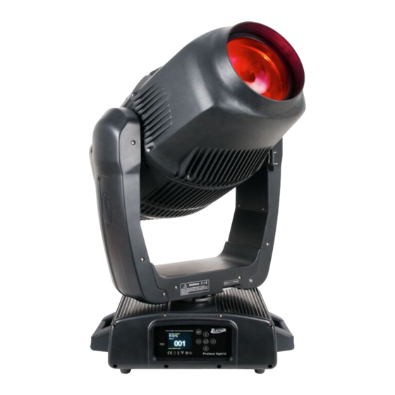
Page 10: Overview
O V E R V I E W Lens E-FLY Wireless DMX Indicator LCD Menu Control Display MODE/ESC Button LEFT Button DOWN Button ENTER Button RIGHT Button UP Button 10. Power IN 11. Fuse 12. RJ45 Ethernet IN 13. Gore Valve 14. -
Page 11: Lamp Installation
L A M P I N S T A L L A T I O N L A M P R E P L A C E M E N T Please note that due to the nature of the Philips™ Platinum 21R Lamp and the optical path of the fixture, the lamp MUST BE replaced at 1,500 hours. - Page 12 L A M P I N S T A L L A T I O N WARNING! LAMP REPLACEMENT SHOULD ONLY BE DONE BE A TRAINED TECHNICIAN. 1. Turn OFF power and allow approximately 60 minutes for the fixture to cool down. TILT Lock Lock...
- Page 13 L A M P I N S T A L L A T I O N 4. Unclip the rear cover safety cable. 5. Remove (4x) 3mm hex-head screws holding the center heatsink module. 6. Unclip the center heatsink module safety cable.
- Page 14 L A M P I N S T A L L A T I O N 7. Gently remove the (2x) spade terminals connected to the lamp. 8. Loosen the lamp retaining arm screw and the pull arm out. Then unclip the lamp retaining clip...
- Page 15 L A M P I N S T A L L A T I O N 9. Swing the lamp retaining clip out, then carefully remove the lamp. WARNING! LAMP MAY BE HOT. USE CAUTION WHEN TOUCHING LAMP WITH BARE HANDS. 10.
- Page 16 HEATSINK MODULE USING A NONABRASIVE BRUSH BEFORE INSTALLING! CAREFULLY INSPECT HEATSINK GASKET FOR SIGNS OF WEAR SUCH AS CRACKING OR HARDENING, DEFORMITIES, OR ALIGNMENT ISSUES BEFORE INSTALLING! ITEMS ABOVE CAN IMPEDE THE IP65 INTEGRITY AND/OR CAUSE INTERNAL DAMAGE. CONTACT ELATION SERVICE REGARDING GASKET REPLACEMENT IF NEEDED.
- Page 17 L A M P I N S T A L L A T I O N T O R Q U E S E T T I N G S F O R S C R E W S HEATSINK MODULE SCREWS MUST BE TIGHTENED WITH A TORQUE WRENCH. The (4x) hex-head screws holding the heatsink module MUST be tightened with a torque 11 lbf-in.
- Page 18 T E S T I N G TO CONFIRM THE IP65 INTEGRITY AFTER A LAMP REPLACEMENT, TEST FIXTURE USING THE ELATION IP TESTER. CONTACT ELATION SERVICE FOR MORE DETAILS. CAUTION! THE USE OF PROTECTIVE GLOVES AND SAFETY GOGGLES IS STRONGLY RECOMMENDED WHILE PERFORMING THE IP PRESSURE TEST! AVOID PLACING YOUR FACE, EYES, HANDS, ETC IN CLOSE PROXIMITY TO THE FIXTURE’S...
-
Page 19: Gobo Installation
G O B O I N S T A L L A T I O N WARNING! GOBO REPLACEMENT SHOULD ONLY BE DONE BE A TRAINED TECHNICIAN. 1. Turn OFF power and allow approximately 60 minutes for the fixture to cool down. TILT Lock Lock... - Page 20 G O B O I N S T A L L A T I O N 4. Unclip the panel safety cable one side of the head. 5. Unclip the panel safety cable on the opposite side of the head.
- Page 21 G O B O I N S T A L L A T I O N 6. Cut the plastic cable-ties holding wires and disconnect connectors attached to the effect module.
- Page 22 G O B O I N S T A L L A T I O N 7. Remove (2x) #2 Philips screws securing effect module. 8. Gently lift GOBO lens away from effect module. 9. Carefully remove the effect module from fixture. 10.
- Page 23 G O B O I N S T A L L A T I O N 12. Carefully remove retaining spring. CAUTION! DO NOT SCRATCH GOBO OR GOBO HOLDER! 13. Carefully separate the GOBO disc from the GOBO Holder. 14. Carefully remove the retaining ring washer attached to the GOBO. SAVE RETAINING RING WASHER FOR USE WITH THE NEW REPLACEMENT GOBO! RETAINING RING MUST BE USED IN ORDER TO PREVENT GOBO BURNING! 15.
- Page 24 CENTER PANELS USING A NONABRASIVE BRUSH BEFORE INSTALLING! CAREFULLY INSPECT GASKETS FOR SIGNS OF WEAR SUCH AS CRACKING OR HARDENING, DEFORMITIES, OR ALIGNMENT ISSUES BEFORE INSTALLING! ITEMS ABOVE CAN IMPEDE THE IP65 INTEGRITY AND/OR CAUSE INTERNAL DAMAGE. CONTACT ELATION SERVICE REGARDING GASKET REPLACEMENT IF NEEDED.
- Page 25 * lbf-in = Pound Force Inches | kgf-cm = Kilogram Force Centimeters CAUTION! DO NOT OVER TORQUE SCREWS AS THIS CAN CAUSE LEAKAGE ISSUES! TO CONFIRM THE IP65 INTEGRITY AFTER A GOBO REPLACEMENT, TEST FIXTURE USING THE ELATION IP TESTER. CONTACT ELATION SERVICE FOR MORE DETAILS.
- Page 26 Extended testing of custom gobo designs is highly recommended prior to using. PLEASE CONTACT ELATION CUSTOMER SUPPORT FOR FURTHER INFORMATION...
- Page 27 Full Color / Solid Area custom gobo designs are NOT RECOMMENDED due to the extreme high temperature optical system which can reach up to 842 F (450 ° ° Custom gobo designs as illustrated below can burn during extended use periods. PLEASE CONTACT ELATION CUSTOMER SUPPORT FOR FURTHER INFORMATION...
-
Page 28: Fixture Installation
F I X T U R E I N S T A L L A T I O N F L A M M A B L E M A T E R I A L W A R N I N G Keep fixture at least 5.0 feet (1.5m) away from any flammable materials, decorations, pyrotechnics, etc. - Page 29 F I X T U R E I N S T A L L A T I O N CLAMP INSTALLATION The fixture can be attached to a metal truss/structure using. When mounting this fixture to truss be sure to secure (2) appropriately rated clamps (not included) to the (2) Omega Brackets (included) Be sure to attach the Safety Cable (included) to the fixture using the safety cable rigging point integrated into the bottom of the fixture.
- Page 30 F I X T U R E I N S T A L L A T I O N OVERHEAD RIGGING Overhead rigging requires extensive experience, including amongst others calculating working load limits, installation material being used, and periodic safety inspection of all installation material and the fixture.
- Page 31 F I X T U R E I N S T A L L A T I O N CONNECTIONS ENSURE ALL CONNECTIONS AND END CAPS ARE PROPERLY SEALED WITH A DIELECTRIC GREASE (AVAILABLE AT MOST ELECTRICAL SUPPLIERS) TO PREVENT WATER CORROSION AND/OR ELECTRICAL SHORT CIRCUIT.
- Page 32 LEDs. This issue is not specific only to ELATION lighting fixtures, it is a common issue with lighting fixtures from all manufacturers. Although there is no true way to fully prevent this issue from happening, the guidelines below can prevent any potential damage from occurring if followed.
-
Page 33: Remote Device Management (Rdm)
R E M O T E D E V I C E M A N A G E M E N T ( R D M ) NOTE: In order for RDM to work properly, RDM enabled equipment must be used through-out the entire system, including DMX data splitters and wireless systems. -
Page 34: System Menu
S Y S T E M M E N U The fixture includes an easy to navigate system menu control panel display where all necessary setting adjustments are made. (See image below) During normal operation, pressing MODE/ESC button once will access the fixture’s main menu. Once in the main menu you can navigate through the different functions and access the sub-menus with the UP, DOWN, RIGHT, and LEFT buttons. - Page 35 SYSTEM MENU Features are subject to change without any prior written notice. *Rotation direction (Clockwise or Counterclockwise) of effects depends on orientation of the fixture head and Pan/Tilt settings. MAIN MENU SUB MENU OPTIONS / VALUES DESCRIPTION (Default Settings in BOLD) FUNCTION Set Dmx Address A001~AXXX...
- Page 36 Features are subject to change without any prior written notice. *Rotation direction (Clockwise or Counterclockwise) of effects depends on orientation of the fixture head and Pan/Tilt settings. MAIN MENU SUB MENU OPTIONS / VALUES DESCRIPTION (Default Settings in BOLD) ON/OFF Address via DMX Address Via DMX No DMX Status...
- Page 37 Features are subject to change without any prior written notice. *Rotation direction (Clockwise or Counterclockwise) of effects depends on orientation of the fixture head and Pan/Tilt settings. MAIN MENU SUB MENU OPTIONS / VALUES DESCRIPTION (Default Settings in BOLD) Reset All Reset all lights Reset Pan&Tilt Reset single scan...
- Page 38 PERSONALITY - Status Settings - Address Via DMX When ON, define the desired DMX address via an external controller. NOTE: This process assumes the fixture DMX address is set to 001. If fixture DMX address is not at 001, you must adjust the channel numbers accordingly in order for this feature to work.
-
Page 39: E-Fly Wireless Dmx Set Up
Make sure to know what E-FLY wireless channels are being used in the area where the fixture is being installed. ELATION E-FLY WIRELESS TRANSCEIVER only has 0-14 wireless channels, NO CH 15. 4. Set fixture DMX address in the Set Dmx Address sub menu of the FUNCTION main system menu. - Page 40 WIRELESS E-FLY INSTALLATION LOCATION GUIDELINES Wireless DMX signal can penetrate walls, glass, metal, and most objects. However, there are many factors that can affect and/or interrupt the wireless DMX signal, one of which is people. Therefore, it is highly recommended to position the wireless antenna a minimum of 9.8 ft. (3m) above audiences and/or above ground level.
-
Page 41: Dmx Channel Functions And Values
D M X C H A N N E L F U N C T I O N S A N D V A L U E S DMX Channel Values / Functions (26, 24, 37 DMX Channels) Supports Software Versions: ≥ 1.8.0 Features subject to change without any prior written notice. - Page 42 Supports Software Versions: ≥ 1.8.0 Features subject to change without any prior written notice. *Rotation direction (Clockwise or Counterclockwise) of effects depends on orientation of the fixture head and Pan/Tilt settings. MODE / CHANNEL VALUE FUNCTION BASIC STAND EXTEND Color Wheel Fine: 0-255 Color Wheel colour change to any position Fine Rotating gobos, cont.
- Page 43 Supports Software Versions: ≥ 1.8.0 Features subject to change without any prior written notice. *Rotation direction (Clockwise or Counterclockwise) of effects depends on orientation of the fixture head and Pan/Tilt settings. MODE / CHANNEL VALUE FUNCTION BASIC STAND EXTEND Fixed Gobos: Open/hole 8-14 Gobo 1...
- Page 44 Supports Software Versions: ≥ 1.8.0 Features subject to change without any prior written notice. *Rotation direction (Clockwise or Counterclockwise) of effects depends on orientation of the fixture head and Pan/Tilt settings. MODE / CHANNEL VALUE FUNCTION BASIC STAND EXTEND Rotating prism, Prism / Gobo macros: 0-31 Open position (hole) 32-64...
- Page 45 Supports Software Versions: ≥ 1.8.0 Features subject to change without any prior written notice. *Rotation direction (Clockwise or Counterclockwise) of effects depends on orientation of the fixture head and Pan/Tilt settings. MODE / CHANNEL VALUE FUNCTION BASIC STAND EXTEND Auto Focus: 0-50 Auto Focus Off 51-150...
- Page 46 Supports Software Versions: ≥ 1.8.0 Features subject to change without any prior written notice. *Rotation direction (Clockwise or Counterclockwise) of effects depends on orientation of the fixture head and Pan/Tilt settings. MODE / CHANNEL VALUE FUNCTION BASIC STAND EXTEND CMY macros: 0-31 32-39 Macro1...
- Page 47 Supports Software Versions: ≥ 1.8.0 Features subject to change without any prior written notice. *Rotation direction (Clockwise or Counterclockwise) of effects depends on orientation of the fixture head and Pan/Tilt settings. MODE / CHANNEL VALUE FUNCTION BASIC STAND EXTEND Control: 0-19 colour change normal 20-29...
-
Page 48: Error Codes
IF A BALLAST ERROR MESSAGE APPEARS, TURN THE LAMP OFF FOR 3-5 MINUTES TO RESET THE BALLAST. IF AFTER 5-MINUTES A BALLAST ERROR STILL APPEARS, TURN THE FIXTURE OFF TO RESET THE BALLAST. IF A BALLAST MESSAGE STILL APPEARS, PLEASE CONSULT ELATION CUSTOMER SUPPORT. - Page 49 E R R O R C O D E S Error Codes are subject to change without any prior written notice. ERROR CODES DESCRIPTION PAN Er The PAN movement is not located in the default position after the reset. This message will appear after a fixture reset if the magnetic-indexing circuit malfunctions (sensor failed or magnet is missing) or there is a motor failure (defective motor or a defective motor IC drive on the main PCB).
- Page 50 E R R O R C O D E S Error Codes are subject to change without any prior written notice. ERROR CODES DESCRIPTION Rotating Gobo The Rotating Gobo rotation movement is not located in the default position after the reset.
- Page 51 E R R O R C O D E S Error Codes are subject to change without any prior written notice. ERROR CODES DESCRIPTION Animation Wheel Er The Animation Wheel movement is not located in the default position after the reset. This message will appear after a fixture reset if the magnetic-indexing circuit malfunctions (sensor failed or magnet is missing) or there is a motor failure (defective motor or a defective motor IC drive on the main PCB).
- Page 52 E R R O R C O D E S Error Codes are subject to change without any prior written notice. ERROR CODES DESCRIPTION Accelerometer Err Accelerometer calibration failure. Accelerometer ID Error Accelerometer fail to read ID information. Ballast Fault_1 Lamp over voltage.
-
Page 53: Maintenance
ALWAYS be done after lamp operation. • Some units may require partial disassembly in order to gain access to the valve. Please contact Elation service for information regarding the location and access procedure for the valve on your specific unit model. -
Page 54: Specifications
13,375 LUX 1,243 FC @49.2’ (15m) (3.0° Spot) 8 / 16 Bit Resolution Adjustable Movement 233,000 LUX 21,646 FC @49.2’ (15m) (2.0° Beam) DMX, RDM, Art-NET, and sACN Protocol Support 11,500 LUX 1,068 FC @16.4’ (15m) (4.0° Wash) Elation’s E-FLY™ Internal Wireless Zoom Range Transceiver Beam 2.1°... -
Page 55: Colors And Gobos
COLORS AND GOBOS... -
Page 56: Dimensional Drawings
D I M E N S I O N A L D R A W I N G S... -
Page 57: Optional Accessories
ITEM TRIGGER CLAMP Heavy Duty Wrap Around Hook Style Clamp ELF001 E-FLY™ Wireless DMX Transceiver DRCPROHYBRID1 Single Road Case for PROTEUS HYBRID DRCPROHYBX2W Dual Road Case for PROTEUS HYBRID IP TESTER IP Fixture Vacuum and Pressure Leak Tester FCC STATEMENT This device complies with Part 15 of the FCC Rules.