Rinnai REU-VA1320WF-US Operation And Installation Manual
Automatic circulating tank water heater
Hide thumbs
Also See for REU-VA1320WF-US:
- Operation and installation manual (44 pages) ,
- Technical data sheet (8 pages) ,
- Operation and installation manual (44 pages)
Table of Contents
Advertisement
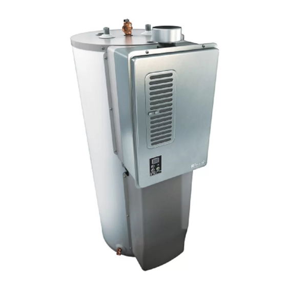
Hybrid Tank-Tankless Water Heater
READ ALL OF THE INSTRUCTIONS THOROUGHLY BEFORE INSTALLING OR OPERATING THIS WATER HEATER.
This manual provides information on the installation, operation, and maintenance of the water heater. For proper
operation and safety, it is important to follow the instructions and adhere to the safety precautions.
A licensed professional must install the water heater according to the exact instructions on pages 4-30.
The consumer must read the entire manual to properly operate the water heater and to have regular maintenance
performed.
WARNING
— Do not store or use gasoline or other flammable vapors and liquids in the vicinity of this or any other
appliance.
— WHAT TO DO IF YOU SMELL GAS
Do not try to light any appliance.
Do not touch any electrical switch; do not use any phone in your building.
Immediately call your gas supplier from a neighbor's phone. Follow the gas supplier's instructions.
If you cannot reach your gas supplier, call the fire department.
— Installation and service must be performed by a licensed professional.
This entire manual must be left for the consumer. The consumer must read and refer
to this manual for proper operation and to maintain the water heater.
If the information in these instructions is not followed exactly, a fire or explosion
may result causing property damage, personal injury or death.
Automatic Circulating Tank Water Heater
Operation and Installation Manual
RH180 (REU-VA1320WF-US)
FOR INDOOR APPLICATIONS ONLY
ANSI Z21.10.3 ● CSA 4.3
C
Low Lead Content
NSF/ANSI 372
US
100000364(03)
3/2017
Advertisement
Table of Contents

Related Manuals for Rinnai REU-VA1320WF-US


Summary of Contents for Rinnai REU-VA1320WF-US
- Page 1 Automatic Circulating Tank Water Heater Operation and Installation Manual Hybrid Tank-Tankless Water Heater RH180 (REU-VA1320WF-US) FOR INDOOR APPLICATIONS ONLY ANSI Z21.10.3 ● CSA 4.3 Low Lead Content NSF/ANSI 372 This entire manual must be left for the consumer. The consumer must read and refer to this manual for proper operation and to maintain the water heater.
-
Page 2: Table Of Contents
If you have any questions or feel that the manual is incomplete contact Rinnai at 1-800-621-9419 Safety Definitions This is the safety alert symbol. This symbol alerts you to potential hazards that can kill or hurt you and others. -
Page 3: Safety Behaviors And Practices For The Consumer And Installer
Safety Behaviors and Practices for the Consumer and Installer WARNING Before operating, smell all around the appliance area Do not adjust the DIP switch unless specifically instructed to do so. for gas. Be sure to smell next to the floor because some gas is heavier than air and will settle on the ... - Page 4 Safety Behaviors and Practices for the Consumer and Installer CAUTION BURN HAZARD. Hot exhaust and vent may cause Hot water outlet pipes leaving the unit can be hot serious burns. Keep away from water heater unit. to touch. In residential applications, insulation Keep small children and animals away from unit.
- Page 5 Safety Behaviors and Practices for the Consumer and Installer WARNING Do not use this appliance if any part has been under This appliance is equipped with a three-prong plug for water. Immediately call a qualified service technician your protection against shock hazard and should be to inspect the appliance and to replace any part of the plugged directly into a properly grounded three-prong control system and any gas control which has been...
-
Page 6: Installation Instructions
Installation Instructions Installer Qualifications General Instructions A licensed professional must install the appliance, DO NOT inspect it, and leak test it before use. The warranty Do not install the RH180 outdoors. will be voided due to improper installation. Do not install the appliance in an area where water The installer should have skills such as: leakage of the unit or connections will result in... - Page 7 Prepare for installation Make sure the water heater and its water lines are protected from freezing. Damage due to freezing is not covered by the warranty. Parts included You must follow the installation instructions and Water heater those in Care and Maintenance for adequate ...
-
Page 8: Determine Installation Location
Determine Installation Location You must ensure that clearances will be met and that Environment the vent length will be within required limits. Air surrounding the water heater is used for Consider the installation environment, water quality, combustion and must be free of any compounds that and need for freeze protection. -
Page 9: Installation Location
Location This water heater is not approved for use in manufactured (mobile) homes or outdoor installations. Attic: Installation of the water heater must be accomplished in such a manner that if the tank or any connection should leak, the flow of water will not cause damage to the structure. For this reason, it is not advisable to install the water heater in an attic or upper floor. -
Page 10: Checklist To Determine Location
Checklist to Determine Installation Location □ The water heater is not exposed to corrosive compounds in the air. □ The water heater location complies with the clearances stated in the manual and on the label, located on the side of the unit. □... -
Page 11: Minimum Clearances
Minimum Clearances The minimum clearances from combustibles or non-combustibles construction, 0 inches from the sides, 0 inches from the back, and 12 inches from the top. For closet installation, 4 inches front, or for alcove installation Clearance to be in accordance with local installation codes and the requirements of the gas supplier. 0”... -
Page 12: Typical Installation Illustration
Typical Installations Hot Water Outlet Hot Water Outlet Valve Temperature-Pressure Relief Valve Cold and Hot Unions Cold Water Supply Valve Cold Water Supply Thermal Expansion Tank 4” B-Vent Combustion Air Screen Operation Unit / Temperature Control Outlet Receptacle Drain Pan M Temperature-Pressure Relief Valve Discharge Pipe (do not cap, plug, or reduce ) -
Page 13: Combustion Air Requirements
Combustion Air Requirements This water heater requires adequate combustion air for ventilation and dilution of flue gases. Failure to provide adequate combustion air can result in unit failure, fire, explosion, serious bodily injury or death. Use the following methods to ensure adequate combustion air is available for correct and safe operation of this water heater. - Page 14 Combustion Air Requirements Confined Space: (Small Room, Closet, Alcove, Utility Room, Etc.) A confined space is defined in the National Fuel Gas Code, ANSI Z223.1/NFPA 54 as "a space whose volume is less than 50 cubic feet per 1000 Btu/hr (4.8 m3 per kW per hour) of the aggregate input rating of all appliances installed in that space."...
- Page 15 Combustion Air Requirements Using Indoor Air For Combustion When using air from other room(s) in the building, the total volume of the room(s) must be of adequate volume (Greater than 50 cubic feet per 1000 Btu/hr). Each Combustion air opening must have at least one square inch of free area for each 1000 Btuh, but not less than 100 square inches each.
-
Page 16: Venting Requirements
MUST not be used on this water burning appliance. heater. Rinnai accepts no liability for damage or injury Use the same diameter Category I connector or vent as if such devices are installed on the vent system with permitted by NFPA 54/ANSI Z223.1 venting tables. - Page 17 Venting Requirements Vent Dampers Vent dampers must be certified in accordance with ANSI Z21.68 Before installing any flue damper, consult the local gas authority and damper manufacturer for proper installation. WARNING Thermal Operated Vent Dampers: Should NOT be used with this appliance. This appliance has a thermal efficien- cy greater than 80%.
- Page 18 Venting Requirements Inspection: The entire length of the vent connector shall be readily accessible for inspection, cleaning and replacement. Joints: Must be fastened by sheet metal screws or other approved methods. Support: Vent connectors must be supported per the vent manufacturer’s installation instructions to avoid dips or sags in the vent and maintain the required clearances.
- Page 19 Venting Requirements Masonry Vertical Venting Masonry Chimneys shall be built and installed in accordance with NFPA 211, Standard for Chimneys, fireplaces, Vents and Solid Fuel-Burning Appliances. Before assembling the vent connector to a chimney, the chimney must be inspected for signs of obstruction or damage.
-
Page 20: Checklist For Combustion Air And Venting
Checklist for Combustion Air and Venting Requirements □ Verify proper clearances around the vents . □ Ensure that the Combustion Air Requirements are followed that will provide sufficient combustion air for the appliance. □ Ensure you have used the correct venting products for Category 1 and that you have completely followed the venting manufacturer’s installation instructions and these installation... -
Page 21: Installation Of Plumbing
Installation of Plumbing INFORMATION Temperature-Pressure Relief Valve Requirements If a T&P discharges periodically, this may be due to thermal expansion in a closed water supply Install the Temperature-Pressure Relief (T&P) Valve system. Contact the water supplier or local according to these instructions. plumbing inspector on how to correct this This water heater is provided with a combination situation. -
Page 22: Checklist For Plumbing
Check for proper water pressure to the water sure all fittings are tight. It is imperative that open heater. Minimum water pressure is 20 psi. Rinnai flame is not applied to the inlet and outlet fittings, recommends 30-50 psi for maximum as heat will damage or destroy the plastic lined performance. -
Page 23: Massachusetts-Required Plumbing
Massachusetts - Required Plumbing RH180 Manual... -
Page 24: Installation Of Gas Supply
MUST DO Installation of Gas Supply A manual gas control valve must be placed in the WARNING gas supply line to the water heater. A union can be used on the connection above the shut off valve 1. If you are not knowledgeable or qualified to for the future servicing or disconnection of the install gas lines or connections, then contact a unit. - Page 25 Pipe Sizing Table - Natural Gas Size the gas pipe Schedule 40 Metallic Pipe The gas supply must be capable of handling the entire gas load at the location. Gas line sizing is based on gas type, Inlet Pressure: less than 2 psi (55 inches W.C.) the pressure drop in the system, the gas pressure sup- Pressure Drop: 0.3 inches W.C.
-
Page 26: Connect Electricity
Connect Electricity Adjust for High Altitude WARNING Set switches 2 and 3 to the values shown in table below for your altitude. The default setting for the Do not use an extension cord or an adapter plug with appliance is 0-2000 ft (0-610 m) with switches No. 2 this appliance. -
Page 27: Final Checklist
Damage due to freezing □ Check for proper water pressure to the water is not covered by the warranty. heater. Minimum water pressure is 20 psi. Rinnai □ Confirm that the electricity is supplied from a 120 recommends 30-50 psi for maximum VAC, 60 Hz power source, is in a properly performance. -
Page 28: Technical Data
Combustion Air Co Sensor Bi-Metal Overheat Switch Rinnai is continually updating and improving products. Therefore, specifications are subject to change without prior notice. The maximum inlet gas pressure must not exceed the value specified by the manufacturer. The minimum value listed is for the purpose of input adjustment. -
Page 29: Dimensions
Dimensions Inches (millimeters) 23.8 (605) (203) 18.7 (475) 24.8 (630) 25.8 (655) 27.5 (698) (254) (508) RH180 Manual... -
Page 30: Wire Diagram
Wire Diagram Wire Color Legend W:..WHITE BK:….BLACK BR:….BROWN R:…...RED RH180 Manual... -
Page 31: Parts Breakdown
Parts Breakdown ITEM DESCRIPTION OF ENGINE PARTS EXHAUST DUCT BOX OVERHEAT SWITCH HEAT EXCHANGER THERMAL FUSE ELECTRODE FLAME ROD MANIFOLD ASSEMBLY P.C.B. IGNITER SURGE PROTECTOR GAS CONTROL ASSEMBLY GAS CONNECTION DRAIN VALVE HOT WATER OUTLET COMBUSTION FAN WATER INLET WATER FILTER ASSEMBLY WATER FLOW SENSOR WATER FLOW CONTROL DEVICE OPERATION UNIT... -
Page 32: Consumer Operation Guidelines For The Safe Operation Of Your Water Heater
Consumer Operation Guidelines for the Safe Operation of your Water Heater FOR YOUR SAFETY READ BEFORE OPERATING WARNING: If you do not follow these instructions exactly, a fire or explosion may result causing property damage, personal injury or loss of life. BEFORE LIGHTING: ENTIRE SYSTEM MUST BE FILLED WITH WATER AND AIR PURGED FROM ALL LINES. -
Page 33: How To Use The Temperature Controller
How to Use the Temperature Controller TEMPERATURE CONTROL Note: Freeze protection will activate as long as gas and electricity are available. Five temperature settings are available. Push the up and down arrows to choose your desired temperature setting. The number on the display corresponds to the temperatures below: 1=110°F 2=120°F 3=130°F... - Page 34 If you install this water heater in an area that is known to have hard water or that causes scale build-up the water must be treated and/or the heat exchanger flushed regularly. Rinnai provides a “Scale Control System” that offers superior lime scale prevention and corrosion control by feeding a blend of control compounds into the water supply.
-
Page 35: Diagnostic Codes And Remedies
Diagnostic Codes and Remedies WARNING Some of the checks below should be done by a licensed professional. Consumers should never attempt any action that they are not qualified to perform. Code Definition Remedy Air Filter Error Follow the procedure “Air Screen Inspection, Detection & Cleaning” in this manual. If the error code continues to flash after cleaning the air filter, review the items in “Code 10”... - Page 36 Code Definition Remedy Thermal Fuse Check for restrictions in air flow around unit and vent terminal. licensed Check gas type of unit and ensure it matches gas type being used. professional only Ensure dip switches are set to the proper position. Check for foreign materials in combustion chamber and/or exhaust piping.
-
Page 37: Air Screen
System Maintenance The appliance must be inspected annually by a licensed professional. Repairs and maintenance should be per- formed by a licensed professional. The licensed professional must verify proper operation after servicing. WARNING To protect yourself from harm, before performing maintenance: ... -
Page 38: Water Filter
Water Filter Inspection, Detection & Cleaning A. Inspection: To maintain optimum performance, periodically inspect the water filter. To clean the water filter follow the cleaning procedure described in Step C. If the water filter appears damaged, contact a qualified service provider for a replacement filter (Part No. 107000032) B. -
Page 39: Required Maintenance
Required Maintenance Water Heater Tank Drain a pail of water through the drain valve at least once a year. This will remove excess sediment from the bottom of the tank. This sediment, if allowed to accumulate, will reduce the efficiency and the life of the tank. Temperature and Pressure-Relief Valve Manually operate the temperature and pressure-relief valve at least once a year, standing clear of the outlet to avoid being burned. - Page 40 Hybrid Tank-Tankless Flush Procedure Use the following procedure to flush the heat exchanger of lime or scale build up. Damage caused by lime build- up is not covered by the unit’s warranty. After flushing, reset any error codes by turning off the power to the unit and turning the power back on.
- Page 41 Manual Draining of the Water Heater WARNING To avoid burns, wait until the equipment cools down before draining the water. The water in the appliance will remain hot after it is turned off. If the water heater is not going to be used during a period of possible freezing weather, it is recommended that the water COLD WATER...
-
Page 42: Freeze Protection And Winterization
Freeze Protection and Winterization Freeze Protection Make sure that in case of freezing weather that the water heater and its water lines are adequately protected to prevent freezing. Damage due to freezing is not covered by the warranty. Refer to the section on Freeze Running a low volume of water through the water heater to prevent freezing If the temperature exceeds the ability of the water heater to freeze Protection. -
Page 43: Consumer Support
Limited Warranty for Hybrid Tank - Tankless What is covered? The Rinnai Standard Limited Warranty covers any defects in materials or workmanship when the product is installed and operated according to Rinnai written installation instructions, subject to the terms within this Limited Warranty document. - Page 44 What will Rinnai do? Rinnai will repair or replace the covered product or any part or component that is defective in materials or workmanship as set forth in the above table. Rinnai will pay reasonable labor charges associated with the repair or replacement of any such part or component during the term of the labor warranty period.
- Page 45 Limitation on warranties No one is authorized to make any other warranties on behalf of Rinnai America Corporation. Except as expressly provided herein, there are no other warranties, expressed or implied, including, but not limited to warranties of merchantability or fitness for a particular purpose, which extend beyond the description of the warranty herein.
- Page 46 ‘ Æ Ç Æ Æ Æ Å > ¨ À ¹ Ä º · À ¯ Á ® º ³ Á · ¹ Ã Â ® Á ³ À ± ¿ ¾ ° ¾ ½ ¼ ³ ¸ ¹ ¯ »...
- Page 47 ‡ “ † ’ ‡ ‚ ƒ ƒ ‹ … Š ‡ ‚ “ ’ ¨ ƒ ‘ € ƒ ¬ Ž † ‡ ‚ ƒ ‚ ‚ ...
- Page 48 Ø > < " & ª ¡ £ ¡ © © £ £ £ £ ¢ ¨ £ ¡ § © § ¥ £ £ ¢ £ ¤ ¢ ¤ £ ¥ ¡ £...
- Page 49 > < è Ø < < < < × < < < < < < < < < < < < < ˆ < × < < < < < < < < ® < < < < < < <...
- Page 50 Ø > < ý ï ì è Ø ë ý Ø è í < < Õ < < ® < < < < < < < © Õ ¬ « > È < < < < < < < <...
- Page 51 > < Ø ¥ ¤ £ ¢ ¢ ¡ © ¡ ¢ ¢ ¡ ¿ ¾ ¥ ¤ " © " & " © ¨ § > & & < & & ¦ © ¥ ¤ ¢...
- Page 52 > < > & < & & > & & & & & & & < > & & & < & & & & & & & & & & > & & & & & < & & &...
- Page 53 ä ß Ü ì í ë ð â í Ü é Ü ã ð ä í â ã ë ê ß ä ò è ð ã â í è Ü é è ä ë ã Ü ã Ü ã ë Ü...
- Page 54 < > ï ï Ü ä ð ã ë æ Ü é â ê ß ë ê Ü à ð é ß ì é è ß ò Ü ê ã Ü ä Ü ê Ü ã ä ë ß ã â...
- Page 55 ¡ Ì ™ € … „ ƒ ’ ” “ ’ ’ “ ¾ ¢ “ ¢ Ÿ ” Ÿ “ ’ š À Á ” – È ¦ — – Ÿ œ Ä Í Ã “ ¦...
- Page 56 ø ÿ û Ô © £ ¨ £ § ¦ ¥ ¤ ¡ £ £ £ ¢ ¡ ¡ ¡ " & & & & " & & & "...
- Page 57 „ ƒ ‚ € ø ¤ ÿ û Ô ø ÿ û ý û ¡ û û ý ø ¤ ÿ ÿ û ÷ ø ø ¢ ¤ ø ý ø ¡ ÿ û ¨ ý ø...
- Page 58 ‹ ” Ž ¡ Ÿ ž œ › š ¼ Ä À Ä À º Ä œ ž Ÿ ‘ ž œ ž Œ œ › œ ž Ë œ ž Ÿ...
- Page 59 ‹ ” Ž ¡ Ÿ ž œ › š ” “ Ž ˆ ‚ ‹ † ƒ ’ ‘ Ž ˆ ƒ ‰ ‹ „ … ‰ ˆ ‰ † Š ‚ ˆ † ˆ...
- Page 60 ” ‹ ” Ž ¡ Ÿ ž œ › š  € € Â Ò ‚ ‚ Ò ‚ ‚ € Õ õ ê ç Ï î Ó Ï æ ç æ è Ñ õ æ ä ð...
- Page 61 ‹ ” Ž ¡ Ÿ ž œ › š Ž Ì Å ¼ à » É Ç Ç À ¿ Ä ¼ ¼ ¼ à » Ä È Ç Ì Ä ¼ ¼ ¼ à »...
- Page 62 ° Ø ² ‹ Ž “ Œ Ž – “ Œ ” Ž „ ƒ ‹ Š — ’ Œ ‚ ˜ ™ ‰ € “ ‘ • ‡ “ “ ’ Œ...
- Page 64 ° Ô ² ˆ § € ‡ Ÿ „ € § § Ÿ § € ƒ Ÿ ƒ € ƒ ¤ ‡ Ÿ ƒ € ƒ ‡ „ ¦ ® ˜ ˆ †...
- Page 65 ° ² Ö ˆ ¦ ¥ ¤ ‡ ‡ £ § € Ÿ € € § ƒ £ € ¢ Ÿ ƒ ƒ ‡ ž ˆ € „ ƒ ...
- Page 66 ° ² ¤ § ž ¯ ƒ ¢ € ‡ § ± & ƒ ¤ ‡ © „ € ¢ … » ¤ § ¸ § ž ¯ ¸ ¡ ƒ „ ¨ ...
- Page 67 © © ¨ § ¦ ¢ ¥ ¡ ¤ £ ¢ ¡ ¡ ...
- Page 68 š ‰ Æ Å Ä ¨ ü ® © ° ± « ¦ ÿ É Í ¢ ø Ñ Ñ Ç Ì Å þ ø È ÷ ¤ Æ É É ¦ þ Ð Ì û É § þ ¦ ËÇ...
- Page 69 ü ‰ ‰ þ À à œ š ˜ ¿ ˜ ‰ ÿ • ‰ Å õ ˜ ¿ „ † † ˆ † õ „ ‡ † … „ „ … „ ¡ û ô “ ô ’ ¡...
- Page 70 Ä ‰ Æ Å Ä ¨ ü ® © ° ± « ¦ ª ± © ¯ © ± ± ¹ ¸ ¨ ± ¹ Â © ® © À § ¶ · ± © » º ¶ ®...
- Page 71 Æ Å Ä ¨ ü ® © ° ± « ¦ Æ ‰ º º ª « ° Ã ¶ » « ª © ± ¹ ¸ ° ¿ ¯ ¹ ¨ © » § « ® © ° Ã...
- Page 72 Â Ä Æ Å Ä ¨ ü ® © ° ± « ¦ ª ± © · ¶ » º º º º º º º º © ¯ ˜ ª ¿ ° » ± ¹ ¸ ¬ © ¨ ±...
- Page 73 ü › š ™ › Â ™ š Á ù Á › À ™ À ¿ › š ™ ‚ › ¾ ™ ‰ ¡ ª ½ ¼ ° ¥ ¤ ° ¬ ® ¦ ¬...
- Page 74 ü û ü...
- Page 75 í ì ¬ « ë ê ¨ é è ç æ € ¬ “ “ “ ç ˆ ¨ ˆ ‚ í ¬ é „ ‰ è „ ç é ç ¿ ˆ é ç é Í §...
- Page 76 ¬ í ì ¬ « ë ê ¨ é è ç æ û ÿ ø ø û ÿ û ø ü ø ÿ ø ÿ ü ÿ ø ü ø ø û û ø ÿ ü ù ø û ÿ ÿ...
- Page 77 í ì ¬ « ë ê ¨ é è ç æ ¬ ü ø û ÿ ø ø ü ÿ ø ø û ú ù ü ø û ÿ ø ÿ ü ø þ þ ø ù ø û ÿ ÿ...
- Page 78 î ¬ í ì ¬ « ë ê ¨ é è ç æ ‘ í í í í í ¬ ¨ ˆ ¨ “ ç è ’ é „ ‡ ¨ è é … ¨ ‘ í...
- Page 79 ® ¬ « ª © ¨ § ¦ ¥ ¤ ¬ Ü è Ü Ü è ç Þ ä Ü Û Ý ï Þ â Û ä Ý ë â Ü è " Û æ Ú æ ì Û ä...
- Page 80 ¬ ¬ ® ¬ « ª © ¨ § ¦ ¥ ¤ € € ƒ ‚ € € € Õ Ø ¨ À © ¥ ¨ ¦ § Å ¦ ¥ Ï ¦ Ì É ¥ © © ¥...
- Page 81 ® ¬ « ª © ¨ § ¦ ¥ ¤ ® ¬ Ú ë Û ä Þ è ã Ü è ð ë Þ ä Ü Û Û ä ð Û Ú Ý â Û ï Û Û Û Ú...
- Page 82 § © " " § § ¨ " " ¨ " " § & & " " © § " & © " " " § " § § § © " © & " § § " § © "...
- Page 83 © ¨ É © © © Å © Å ¶ © © © © © © © © © © © © Ç Æ © Å © ¦ © © © © © © © Í © © © ©...
- Page 84 Á © ¨ © © © © © © © Å © © Å Å Ë © © © ¦ © © © Í © © © © © © ç Í Í Í © © © © Æ © Å...
- Page 85 ¥ ¯ ® ¤ ¨ ¨ ¤ ¬ ¥ « ª © ¬ § ¤ ž š œ š š œ š œ š œ œ š š ¬ § ¨ ¤ Ç È ¥ È...
- Page 86 š › œ š š œ š œ š œ œ œ š › š š š œ š Ÿ š š š ¨ š œ ¨ š œ › š œ š Ÿ ¨ š š ¨...
- Page 87 – § ¨ ¥ ¢ ¨ § © ¨ © ¡ ¨ œ š ž ¡ Ÿ ž ¡ Ÿ ¡ ¡ ¡ ž Ÿ › š œ š © ¨ š ¢ š œ...
- Page 89 È « Ç ¦ Æ È ¬ § © ¬ § Å ® Æ § Ç « ž ¡ ¡ › š œ š › › š › š œ ...
- Page 90 £ ¢ ¡ ü û ÿ þ ý ü û ú ù õ ú ù ó ø ÷ ö õ ò ô ó ò ¦ ¥ ¤ ñ î í í ì ï ð ï ë à ç ê é...