
Related Manuals for Lowrance X100C


Summary of Contents for Lowrance X100C
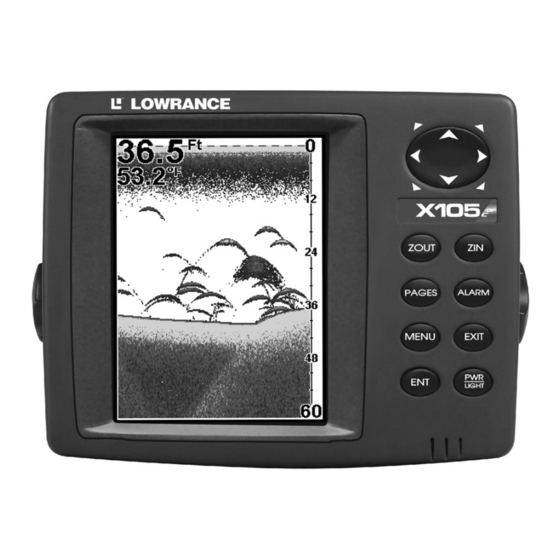
- Page 1 Pub. 988-0156-001 www.lowrance.com X100C & X105C DF Fish-finding & Depth Sounding Sonars Installation and Operation Instructions...
- Page 2 Lowrance is a registered trademark of Lowrance Electronics, Inc. Lowrance Electronics may find it necessary to change or end our policies, regulations, and special offers at any time. We reserve the right to do so without notice. All features and specifications subject to change without notice.
-
Page 3: Table Of Contents
Sec. 1: Read Me First! ... 1 Capabilities and Specifications: X100C, X105C DF... 2 How Sonar Works ... 3 How to Use this Manual: Typographical Conventions... 4 Sec. 2: Installation & Accessories ... 5 Preparations... 5 Transducer Installation... 5 Selecting a Transducer Location ... 6 How Low Should You Go?... - Page 4 Sensitivity & Auto Sensitivity... 62 Turn Auto Sensitivity Back on: ... 63 Sonar Color Mode... 64 Sonar Page & Sonar Chart Display Options ... 64 Full Sonar Chart ... 64 Split Zoom Sonar Chart ... 65 Digital Data/Chart ... 65 Customizing the Digital Data/Chart Screen...
-
Page 5: Sec. 1: Read Me First
First, we want to thank you for buying a Lowrance sonar. Whether you're a first time user or a professional fisherman, you'll discover that your unit is easy to use, yet capable of handling demanding sonar tasks. -
Page 6: Capabilities And Specifications: X100C, X105C Df
Case size:... 5.4" H x 6.9" W x 3.4" D (13.8 x 17.6 x 8.6 Back-up memory: ... Built-in memory stores user settings for Languages:... 10; menu languages selectable by user. Frequency:... 50/200 kHz for X105C DF; 200 kHz for X100C. Transducers: ... A dual-frequency Skimmer Maximum transmitter power: ... -
Page 7: How Sonar Works
Service Department; phone numbers are listed on the last page. How Sonar Works Sonar has been around since the 1940s, so if you already know how it works, skip ahead to the next segment on the typographical conventions used in this manual. But, if you've never owned a sonar fish finder, this segment will tell you the under water basics. -
Page 8: How To Use This Manual: Typographical Conventions
Instructions = Menu Sequences Most functions you perform with the sonar unit are described as a se- quence of key strokes and selecting menu commands. We've written them in a condensed manner for quick and easy reading. -
Page 9: Sec. 2: Installation & Accessories
Installation & Accessories Preparations You can install the sonar system in some other order if you prefer, but we recommend this installation sequence: Caution: You should read over this entire installation section before drill- ing any holes in your vessel! 1. -
Page 10: Selecting A Transducer Location
If the transducer is not placed in a smooth flow of water, interference caused by bubbles and turbulence will show on the sonar's display in the form of random lines or dots whenever the boat is moving. -
Page 11: How Low Should You Go
5. If possible, route the transducer cable away from other wiring on the boat. Electrical noise from engine wiring, bilge pumps and aerators can be displayed on the sonar's screen. Use caution when routing the transducer cable around these wires. -
Page 12: Shoot-Thru-Hull Vs. Transom Mounting
Shoot-thru-hull vs. Transom Mounting In a shoot-thru-hull installation, the transducer is bonded to the inside of the hull with epoxy. The sonar "ping" signal actually passes through the hull and into the water. This differs from a bolt-thru-hull installa- tion (often called simply "thru-hull"). In that case, a hole is cut in the hull and a specially designed transducer is mounted through the hull with a threaded shaft and nut. -
Page 13: Transom Transducer Assembly And Mounting
Lack of angle adjustment can be particularly troublesome on hulls that sit with the bow high when at rest or at slow trolling speeds. Third, a transducer CAN NOT shoot through wood and metal hulls. Those hulls require either a transom mount or a thru-hull installation. Fourth, if your Skimmer transducer has a built in temp sensor, it will only show the temperature of the bilge, not the water surface temp. - Page 14 Place the ratchets into the bracket with the letter "A" aligned with the alignment mark molded into the bracket. Place the ratchets onto the transducer with the letter "A" aligned with the 12 o'clock position on the transducer stem. These positions set the transducer's coarse angle adjustment for a 14°...
- Page 15 If the transducer's face isn't parallel with the ground, remove the transducer and ratchets from the bracket. Place the ratchets into the holes in the bracket with the letter "B" aligned with the dot stamped in the bracket. Reassemble the transducer and bracket and place them against the transom.
- Page 16 Bolt Flat washer Assemble transducer and bracket. 3. Assembling the transducer. A. One-piece bracket: Once you determine the correct position for the ratchets, assemble the transducer as shown in the following fig- ure. Don't tighten the lock nut at this time. Assemble transducer and bracket.
- Page 17 Transom Transom Position transducer mount on transom and mark mounting holes. Side view shown at left and seen from above at right. 5. Attaching transducer to transom. A. One-piece bracket: Remove the transducer from the bracket and re-assemble it with the cable passing through the bracket over the bolt as shown in the following figures.
- Page 18 Electrical noise from the engine's wiring, bilge pumps, VHF radio wires and cables, and aerators can be picked up by the sonar. Use cau- tion when routing the transducer cable around these wires.
-
Page 19: Trolling Motor Bracket Installation
(not included) to attach the transducer cable to the troll- ing motor shaft. Make sure there is enough slack in the cable for the motor to turn freely. Route the cable to the sonar unit and the trans- ducer is ready for use. -
Page 20: Shoot-Thru-Hull Preparation And Installation
The transducer installation inside a fiberglass hull must be in an area that does not have air bubbles in the resin or separated fiberglass lay- ers. The sonar signal must pass through solid fiberglass. A successful transducer installation can be made on hulls with flotation materials (such as plywood, balsa wood or foam) between layers of fiberglass if the material is removed from the chosen area. - Page 21 When the job is finished, the hull is watertight and structurally sound. Remember, the sonar signal must pass through solid fiberglass. Any air bubbles in the fiberglass or the epoxy will reduce or eliminate the sonar signals.
- Page 22 1. Anchor the boat in about 30 feet of water. Add a little water to the sump of the boat. Plug the transducer into the sonar unit, turn it on, then hold the transducer over the side of the boat in the water. Adjust the sensitivity and range controls until a second bottom echo is seen on the display.
- Page 23 4. Most people can get good results by following steps 1 through 3, so this step is optional. If you want to make an extra effort to be absolutely sure that your selected location will work under all conditions, make a test run with the boat on plane and observe the bottom signal.
-
Page 24: Speed/Temperature Sensors
Leave the weight in place for a minimum of three hours. Allow the epoxy to cure for 24 hours before moving the boat. 5. After the epoxy has cured, route the cable to the sonar unit and it's ready to use. - Page 25 Recommended tools for this job include: drill, 7/8" drill bit, 1/8" drill bit for pilot holes, screwdriver. Required supplies for this job include: four #8 stainless steel wood screws (3/4" long), high quality, marine grade above- or below-waterline sealant. First find a location on the boat's transom where the water flow is smoothest.
-
Page 26: Power Connections
The sensor is now ready for use. Connect the sensor to the sonar socket on the back of your unit and connect the transducer to the speed sen- sor's socket. - Page 27 connected to another power source. If your NMEA 2000 buss is already powered, you can ignore the NMEA 2000 Power cable. Never attach two power sources to a single NMEA 2000 buss. If you do need to power your NMEA 2000 buss, attach the NMEA 2000 Power cable to your boat's battery just as indicated in the following segment for connecting your unit's Power Supply cable.
- Page 28 For example, if you have to extend the power cable to the battery or power buss, attach one end of the fuse holder directly to the battery or power buss. This will protect both the unit and the power cable in the event of a short.
-
Page 29: Nmea 2000 Cable Connections
NMEA 2000 buss installed. Over the next few years, however, NMEA 2000 will become much more common. To help you get the most out of this technology, your Lowrance unit is designed to work with a NMEA 2000 network as soon as it becomes available. -
Page 30: Mounting The Unit: Bracket, In-Dash Or Portable
Sonar unit, rear view Power/Data socket NMEA 0183 data cable (unused) NMEA 2000 Power cable Power Supply cable Mounting the Unit: Bracket, In-Dash or Portable You can install the unit on the top of a dash with the supplied gimbal bracket. - Page 31 Optional R-A-M mounting system. Bracket Installation Mount the unit in any convenient location, provided there is clearance behind the unit when it's tilted for the best viewing angle. You should also make sure there is enough room behind the unit to attach the power, transducer and data cables.
- Page 32 Millimeter Front view (left) and side view (right) showing dimensions of the X100C or X105C DF when mounted on gimbal bracket. After drilling the hole, pass the transducer connector up through the hole from under the dash. Pass the power cable's bare-wire end down though the hole from the top.
-
Page 33: Other Accessories
Portable Installation Like many Lowrance products, this sonar unit is capable of portable operation by using an optional portable power pack. The power pack and an optional portable transducer expand the uses for your sonar unit. -
Page 34: Face Cover
Otherwise, wind blast can pop off the cover. Now that you have your unit installed, move on to Section 3, Basic So- nar Operations. There, we'll present a series of step-by-step tutorials to teach you the basics of Lowrance sonar operation. -
Page 35: Sec. 3: Basic Sonar Operation
Options & Other Features, will discuss other more advanced functions and utilities. Material in Sec. 4 is arranged in alphabetical order. Before you turn on the sonar unit, it's a good idea to learn about the different keys, the Main Menu, the four Page screens and how they all work together. -
Page 36: Power/Lights (Turn Unit On And Off)
This sonar unit will work fine right out of the box with the factory default settings. But, if you want to learn about the various sonar options, see Sec. - Page 37 Sounds command: enables or disables the sounds for key strokes and alarms and sets the alarm style. Transparency command: adjust the level of transparency for dialogs. Sonar Alarms command: turns sonar alarms on or off and changes alarm thresholds. Units of Measure command: changes the depth, speed, distance, or temperature units of measure.
- Page 38 The list of display options appears in the following image. Pages Menu, showing some Sonar display options. All of the display options show the sonar chart in some format. This is a "cross-section" view of the water column beneath the boat. The chart moves across the screen, displaying sonar signal echoes that represent fish, structure and the bottom.
- Page 39 Sonar chart display options (from left) split zoom and digital data. Sonar chart display options (from left) FlashGraf and flasher. Sonar Page Menu. Most of these functions are discussed in Sec. 4.
- Page 40 Structure Sonar Page, showing full sonar chart mode. You can customize how the Sonar Page displays its pictures and other data in many ways. Your unit also includes several special sonar features and options that can help you better interpret the underwater scene.
-
Page 41: Basic Sonar Quick Reference
The auto settings will track the bottom, displaying it in the lower por- tion of the screen. The full sonar chart will scroll from right to left, showing you what's under the boat as you cruise across the water. -
Page 42: Sonar Operations
As you can see from the quick reference on the previous page, basic operation is pretty easy, right out of the box. If you are a sonar novice, try operating the unit with the factory defaults until you get a feel for how it's working. - Page 43 ↑ to increase sensitivity. When it's set at the desired level, press . (When you reach the maximum or minimum limit, a tone sounds.) EXIT At left, Sonar Menu with Sensitivity command selected. At right, the Sensitivity Control Bar.
-
Page 44: Fish Symbols Vs. Full Sonar Chart
Fish I.D. fish symbol feature. Here's why. Fish I.D. is an easier way for a sonar novice to recognize a fishy signal return when he sees it. However, locating fish by symbol only has some limitations. -
Page 45: Other Free Training Aids
Aside from being just plain fun, this program can help you learn both basic and advanced operations without burning boat fuel! Lowrance is one of the first sonar manufacturers to provide this type of training tool for customers. - Page 46 Notes...
-
Page 47: Sec. 4: Sonar Options & Other Features
Material in this section is arranged in alphabetical order. ASP (Advanced Signal Processing) The ASP feature is a noise rejection system built into the sonar unit that constantly evaluates the effects of boat speed, water conditions and interference. This automatic feature gives you the best display pos- sible under most conditions. -
Page 48: Alarms
EXIT EXIT Alarms This unit has three different types of sonar alarms. The first is the Fish Alarm. It sounds when the Fish I.D. feature determines that an echo is a fish. Another alarm is the Zone Alarm, which consists of a bar on the side of the screen. -
Page 49: Zone Alarm
3. Press ← to HALLOW 4. To turn off the alarm, press To switch to a different depth setting, open the Sonar Alarms menu and repeat the instructions in step 3 above. To adjust and turn on the deep alarm: 1. -
Page 50: Fish Alarm
EXIT EXIT ABLED To switch to a different depth setting, open the Sonar Alarms menu and repeat the instructions in steps 3 and 4 above. Fish Alarm Use the fish alarm for a distinctive audible alarm when fish or other suspended objects are detected by the Fish I.D.... -
Page 51: Calibrate Speed
50 percent. If you are drifting slowly, try a chart speed around 75 percent. When you are stationary and a fish swims through the sonar signal cone, the image appears on the screen as a long line instead of a fish arch. Reducing the chart speed may result in a shorter line that more closely resembles a regular fish return. -
Page 52: Colorline
At left, Sonar Page menu with Chart Speed command selected. At right, Chart Speed Control Bar. If you do experiment with chart speed, remember to reset it to maxi- mum when you resume trolling or moving across the water at higher speed. -
Page 53: Depth Cursor
At left, Sonar Page menu with ColorLine command selected. At right, the ColorLine control bar. To adjust the ColorLine level: 1. From the Sonar Page, press 2. The ColorLine Control Bar appears. Press ↓ to decrease ColorLine; press ↑ to increase Colorline. -
Page 54: Depth Range - Automatic
At left, Sonar Page menu with Depth Cursor command selected. At right, sonar chart with the depth cursor active. The line indicates the The cursor can be moved to any location on the screen, letting you pin- point the depth of a target. -
Page 55: Depth Range - Manual
This feature lets you "zoom in" the display in almost unlimited combinations. Nearly any segment of the water column, from the surface to the bottom can be shown. This enlarges the sonar targets to best suit your fishing needs and water conditions. - Page 56 At left, Sonar Page Menu with Upper and Lower Limits command se- lected. At right, Sonar Chart Limits menu, with Upper Limit selected. To change the upper and lower limits: 1. From the Sonar Page, press The Sonar Chart Limits menu appears, with Upper Limit selected.
-
Page 57: Fastrack
The sonar's microcomputer is sophisticated, but it can be fooled. It can't distinguish between fish and other suspended objects such as trotlines, turtles, submerged floats, air bubbles, etc. -
Page 58: Fishtrack
Does that mean Fish I.D. is broken? No — the feature is simply inter- preting sonar returns in a specific way to help take some of the work out of reading the screen. Remember: Fish I.D. is one of the many tools we provide so you can analyze your sonar returns for maximum fish finding information. -
Page 59: Frequency (Change Transducer Frequency)
Sonar Features menu with Fish I.D. Depths selected (at left, dual- frequency menu; center, single-frequency menu). When the check box to the left is checked, the feature is on. At right, Sonar Page showing Fish I.D. symbols and FishTrack depths turned on. -
Page 60: Hyperscroll
See the entry on Ping Speed, which controls the HyperScroll feature. Noise Rejection See the entry on Advanced Signal Processing in this section. Overlay Data To change the digital data shown "floating" on top of the Sonar Page: To select data for display: 1. Press |↓ to MENU 2. -
Page 61: Turn Off Displayed Data
Overlay Data command on the Sonar Menu, at left. Overlay Data Shown selection menu, right. In this example, we scrolled down the data list to highlight "Ground Speed." When selected, the data type shifts to the top of the data list and a check mark appears beside the data type. -
Page 62: Change Displayed Data Font Size
Ping Speed & HyperScroll Ping Speed controls the rate at which the transmitter and transducer broadcast sonar sound waves — pings — into the water. The unit has a default ping speed of 50 percent. At normal boating speeds, this auto- matically provides enough return echoes to refresh the screen and scroll the chart at maximum chart speed. -
Page 63: Change Ping Speed
When you turn HyperScroll off, you can return to your original sensitivity level. At left, Sonar Menu with Ping Speed command selected. Ping Speed Control Bar, right, at default setting. -
Page 64: Turn Off Hyperscroll
PTIONS 2. Press ← to 3. All the menus are cleared and the unit reverts to the full sonar chart, just as if you had turned it on for the first time. All options have been returned to the factory settings. -
Page 65: Set Keel Offset
from an optional water speed sensor. The Water Distance window can be reset to zero using the Reset Water Distance command. Press MENU MENU cleared and the water distance is reset to 0.00. Set Keel Offset This unit measures water depth from the face of the transducer. Since the transducer is installed below the water surface, the distance dis- played by the digital depth, chart depth scale, chart cursor or fish sym- bols is not the exact water depth. -
Page 66: Sensitivity & Auto Sensitivity
1. Press MENU 2. The Keel Offset dialog box appears with a plus (+) sign at the front of the box. 3. Press → to the first number, then press ↑ to change the number to 1. 4. Press → to the second number, them press ↑ to change the num- ber to 5, then press the water depth from surface to bottom. -
Page 67: Turn Auto Sensitivity Back On
. (When you reach the maximum or minimum limit, a tone sounds.) EXIT At left, Sonar Menu with Sensitivity command selected. At right, the To adjust sensitivity in manual mode: 1. First, turn off Auto Sensitivity: from the Sonar Page, press ENSITIVITY 2. -
Page 68: Sonar Color Mode
Sonar Color Mode The default color scheme for the sonar chart is white background, but we offer other variations to suit your viewing preferences. You can se- lect the chart to be displayed in grayscale, reverse grayscale, blue back- ground, or Nightview, IceView, or bottom color tracking. -
Page 69: Split Zoom Sonar Chart
The zoom range shows at the bottom left corner of the screen. Split Zoom Sonar Chart. Image at left shows the left window zoomed to 2X. The right image shows the left window zoomed to 4X. -
Page 70: Customizing The Digital Data/Chart Screen
Customizing the Digital Data/Chart Screen The Digital Data/Chart screen can be customized to show digital data different from the defaults first shown. To customize this screen: 1. From the Sonar Page (in Digital Data mode), press |↓ to MENU USTOMIZE At left, the Sonar Menu showing the Customize command highlighted. -
Page 71: Flashgraf
Tip: You can customize other digital data boxes before returning to the Sonar Page. After changing the first box by selecting the Data Type and pressing Enter, use the ↓ key to select another box to change. When the selected box title bar flashes, press data type| . -
Page 72: Flasher
All sonar features and functions are useable. When in simulator mode, you will see the chart file name in the Sonar Page title bar and a play symbol will flash on and off at the right end of the title bar. -
Page 73: Stop Chart
If you are running multiple units on a boat or using this unit in a car, there are times when you may want to turn off the sonar. This com- mand turns off the sonar and stops the chart from scrolling. Sonar re- starts automatically each time you turn on your unit. -
Page 74: Upper And Lower Limits
Sonar Features menu with Surface Clarity selected (at left, dual- frequency menu; at right, single-frequency menu). 2. Press ↓ or ↑ to select clarity level| Surface clutter In the illustration at left, Surface Clarity is turned off. The right view shows Surface Clarity set at High. -
Page 75: Zoom Pan
Press the Zoom Out key, , to return the display to the normal mode. ZOUT At left, Sonar Page, normal view. Center, same view zoomed to 2X. Right, same view zoomed to 4X Zoom Pan Your unit has the handy ability to quickly zoom in on any portion of the water column with just the touch of an arrow key. - Page 76 Notes...
-
Page 77: Sec. 5: Sonar Troubleshooting
Unit freezes, locks up, or operates erratically: 1. Electrical noise from the boat's motor, trolling motor, or an accessory may be interfering with the sonar unit. Rerouting the power and trans- ducer cables away from other electrical wiring on the boat may help. - Page 78 1. The transducer may be in turbulent water. It must be mounted in a smooth flow of water in order for the sonar to work at all boat speeds. Air bubbles in the water disrupt the sonar signals, interfering with its ability to find the bottom or other targets.
- Page 79 For example, turn on the bilge pump and view the sonar display for noise. If no noise is present, turn the pump off, then turn on the VHF radio and transmit.
- Page 80 Notes...
-
Page 81: Sec. 6: Supplemental Material
Section 6: Supplemental Material Accessories, 1, 26, 27, 29, 30 Sec. 2, Installation & Accessories, 5 Alarms, 32, 33, 44, 45, 46 Depth Alarms, 44 Fish Alarm, 44, 46, 47 Zone Alarm, 44, 45, 46 Antenna, 75 ASP (Advanced Signal Processing), 18, 43 Backlights / Lighting, 2, 31 Batteries, 5, 23, 24, 73, 74, 75... - Page 82 Simulator, 33, 68, 69 Sonar Chart Display Options, 31, 32, 35, 40, 64, 65, 66, 67, 68 Sonar Menu, 39, 43, 57, 59, 63, 66, 69 Sonar Operation Quick Reference, 37 Speed Sensors, 3, 20, 21, 22, 47, 61, 65...
- Page 83 Notes...
- Page 84 Notes...
- Page 85 LOWRANCE ELECTRONICS FULL ONE-YEAR WARRANTY "We," "our," or "us" refers to LOWRANCE ELECTRONICS, INC., the manufacturer of this product. "You" or "your" refers to the first person who purchases this product as a consumer item for personal, family or household use.
-
Page 86: How To Obtain Service
…in the USA: We back your investment in quality products with quick, expert service and genuine Lowrance parts. If you're in the United States and you have technical, return or repair questions, please contact the Factory Customer Service Department. Before any product can be returned, you must call customer service to determine if a return is necessary. - Page 87 To locate a Lowrance dealer near you, visit our web site, www.lowrance.com and look for the Dealer Locator. Or, you can consult your telephone directory for listings.
- Page 88 Visit our web site: Lowrance Pub. 988-0156-001 © Copyright 2004 All Rights Reserved Printed in USA 012304 Lowrance Electronics, Inc.