Table of Contents
Advertisement
Available languages
Available languages
Quick Links
OPERATOR'S MANUAL
Manual del operador
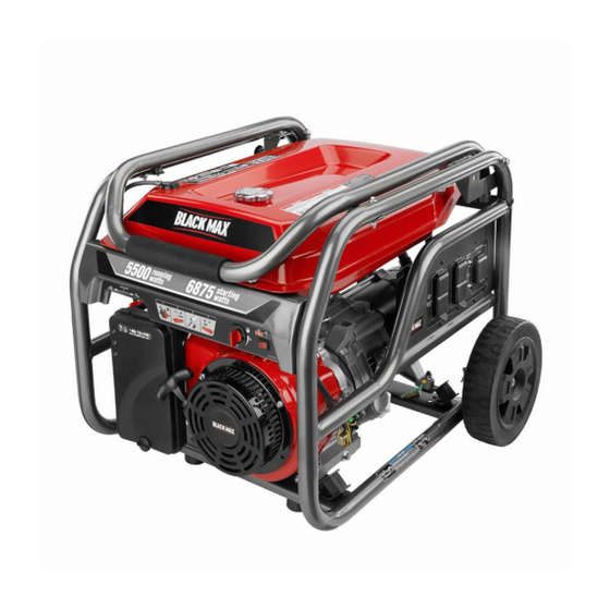
5,700 WATT GENERATOR
Generador 5 700 watts
BM905700PA
Your generator has been engineered and manufactured to our high standard for dependability, ease of operation, and operator
safety. When properly cared for, it will give you years of rugged, trouble-free performance.
WARNING:
this product. If you do not understand the warnings and instructions in the operator's manual, do not use this product.
Thank you for your purchase.
SAVE THIS MANUAL FOR FUTURE REFERENCE
Su generador portàtil diseñado y fabricado de conformidad con nuestras estrictas normas para brindar fiabilidad, facilidad de
uso y seguridad para el operador. Con el debido cuidado, le brindará muchos años de sólido funcionamiento y sin problemas.
ADVERTENCIA:
antes de usar este producto. Guarde este manual del operador y estúdielo frecuentemente para lograr un funcionamiento
seguro y continuo de este producto.
Le agradecemos su compra.
GUARDE ESTE MANUAL PARA FUTURAS CONSULTAS
R
To reduce the risk of injury, the user must read and understand the operator's manual before using
Para reducir el riesgo de lesiones, el usuario debe leer y comprender el manual del operador
CUSTOMER SERVICE
1-800-726-5760
SERVICIO AL CLIENTE
01 800 843 1111
To register your BlackMax product, please visit:
http://register.blackmaxtools.com/
Para registrar su producto de BlackMax, por
favor visita: http://register.blackmaxtools.com/
NOTICE
Do not use E15 or E85 fuel (or
fuel containing greater than
10% ethanol) in this product.
It is a violation of federal law and will damage the unit and
void your warranty.
No utilice combustibles E15 o E85 (ni combustibles que
contengan más de 10 % de etanol) con este producto. Esto
constituye una violación a la ley federal, dañará la unidad
y anulará la garantía.
NEUTRAL BONDED TO FRAME
PUNTO NEUTRO CONECTADO AL MARCO
AVISO
Advertisement
Chapters
Table of Contents

Related Manuals for Black Max BM905700PA


Summary of Contents for Black Max BM905700PA
- Page 1 Manual del operador Para registrar su producto de BlackMax, por favor visita: http://register.blackmaxtools.com/ 5,700 WATT GENERATOR Generador 5 700 watts BM905700PA NOTICE AVISO Do not use E15 or E85 fuel (or fuel containing greater than 10% ethanol) in this product.
- Page 2 See this fold-out section for all of the figures referenced in the operator’s manual. Consulte esta sección desplegable para ver todas las figuras a las que se hace referencia en el manual del operador. Fig. 1 A - Handle release pin (conjunto de pasador de G - Oil drain plug (tapón de drenaje del aceite) N - Fuel valve (válvula de combustible) afloje de mango)
- Page 3 Fig. 2 Fig. 3 Fig. 5 Fig. 7 A - Socket wrench (llave de casquillo) B - Adjustable wrench (llave ajustable) Fig. 4 A - Axle (eje) B - Wheel (rueda) C - Spacer (écarteur, espaciador) D - U-bracket (soporte en “U”) E - Hitch pin (pasador del enganche) Fig.
- Page 4 Fig. 8 Fig. 11 Fig. 14 Fig. 15 A - Move choke lever left to start (desplace A - Oil cap/dipstick (tapa de relleno de aceite / izquierda la palanca del anegador para arrancar) varilla medidora de aceite) B - Move choke lever right to run (desplace B - Oil fill hole (agujero de llenado de aceite) derecha de la palanca del anegador para poner en marcha)
- Page 5 Fig. 19 Fig. 21 Fig. 17 A - Carburetor drain screw (tornillo de drenaje A - Spark plug (bujía) del carburador) B - Spark plug cap (tapa de la bujía) A - Fuel valve (válvula de combustible) Fig. 22 B - Petcock (llave de purga) Fig.
-
Page 6: Table Of Contents
TABLE OF CONTENTS Introduction ..................................2 Important Safety Instructions .............................3-4 Specific Safety Rules ..............................4 Symbols ..................................5-7 Electrical ..................................8-9 Features ..................................10 Assembly ................................11-12 Operation ................................12-14 Maintenance ................................15-17 Troubleshooting ................................18 ... -
Page 7: Important Safety Instructions
IMPORTANT SAFETY INSTRUCTIONS Do not start or operate the engine in a confined space, building, near open windows, or in other unventilated space DANGER: where dangerous carbon monoxide fumes can collect. Carbon Monoxide. Using a generator indoors CAN KILL Carbon monoxide, a colorless, odorless, and extremely YOU IN MINUTES. -
Page 8: Specific Safety Rules
IMPORTANT SAFETY INSTRUCTIONS Use only authorized replacement parts and accessories Maintain the unit per maintenance instructions in this and follow instructions in the Maintenance section of this Operator’s Manual. manual. Use of unauthorized parts or failure to follow main- ... -
Page 9: Symbols
SYMBOLS The following signal words and meanings are intended to explain the levels of risk associated with this product. SYMBOL SIGNAL MEANING Indicates an imminently hazardous situation, which, if not avoided, will result DANGER: in death or serious injury. Indicates a potentially hazardous situation, which, if not avoided, could result WARNING: in death or serious injury. - Page 10 SYMBOLS Some of the following symbols may be used on this product. Please study them and learn their meaning. Proper interpretation of these symbols will allow you to operate the product better and safer. SYMBOL NAME DESIGNATION/EXPLANATION Amperes Current Hertz Frequency (cycles per second) Watt Power...
- Page 11 SYMBOLS GROUNDING WARNING FUEL WARNING National Electric Code requires generator to be grounded No smoking when filling with gasoline. Do not overfill. Full to an approved earth ground. level is 1 in. below the top of the fuel neck. Stop the engine for five minutes before refueling to avoid the heat from the muffler igniting fuel vapors.
-
Page 12: Electrical
ELECTRICAL EXTENSION CORD CABLE SIZE Refer to the table below to ensure the cable size of the extension cords you use are capable of carrying the required load. Inadequate size cables can cause a voltage drop, which can burn out the appliance and overheat the cord. Load in Watts Maximum Allowable Cord Length Current in... - Page 13 ELECTRICAL GENERATOR CAPACITY POWER MANAGEMENT To prolong the life of the generator and attached devices, Make sure the generator can supply enough continuous (run- it is important to take care when adding electrical loads to ning) and surge (starting) watts for the items you will power at the same time.
-
Page 14: Features
FEATURES PRODUCT SPECIFICATIONS ENGINE Rated Starting Watts ..........7,125 W Engine Type ............414cc OHV Rated Frequency ............60 Hz Fuel Volume ..............6 gal. DIMENSIONS Length ..............28.5 in. GENERATOR Width ............... 20.9 in. Rated Voltage ...........120V / 240V Rated Amps ..........47.5 A / 23.8A Height .............. -
Page 15: Assembly
ASSEMBLY UNPACKING LOOSE PARTS LIST See Figure 2. This product requires assembly. The following items are included with the generator: Carefully cut the box down the sides then remove the machine and any accessories from the box. Make sure that all items listed in the loose parts list are included. -
Page 16: Operation
ASSEMBLY Insert a spacer into the center of the wheel. CAUTION: Slide axle through the spacer and wheel, then through the U-bracket frame on generator. Do not attempt to lift the unit by the handle assembly. If Insert hitch pin to secure. it is necessary to lift the generator, always grasp by the frame. - Page 17 OPERATION OXYGENATED FUELS RAISING AND LOWERING THE HANDLE See Figure 6 - 7. NOTICE: To raise the handle (for moving the generator): pull the Do not use E15 or E85 fuel (or fuel containing greater handle up until the handle release knob snaps into lock- than 10% ethanol) in this product.
- Page 18 OPERATION NOTE: Do not allow the grip to snap back after starting; Turn the fuel valve to the OFF position. return it gently to its original place. Allow 30 minutes of “cool down” time before storing the Allow the engine to run for 15-30 seconds, then move machine.
-
Page 19: Maintenance
MAINTENANCE WARNING: WARNING: Do not change engine lubricant while it is hot. Accidental When servicing, use only identical replacement parts. contact with hot engine lubricant could result in serious Use of any other parts can create a hazard or cause burns. - Page 20 MAINTENANCE Retighten drain screw. SPARK ARRESTOR See Figure 18. NOTE: Consult hazardous waste management guidelines in your area for the proper way to dispose of used fuel. Inspect the spark arrestor for breaks or holes. Replace if necessary. To purchase a replacement spark arrestor contact REPLACING FUEL FILTER: BlackMax customer service at 1-800-726-5760.
- Page 21 MAINTENANCE STORAGE When preparing the generator for storage, allow the unit to cool completely then follow the guidelines below. STORAGE TIME PRIOR TO STORING Less than 2 months Drain gasoline from tank and dispose of in a suitable container according to state and local ordinances. 2 months to 1 year ...
-
Page 22: Troubleshooting
TROUBLESHOOTING PROBLEM POSSIBLE CAUSE SOLUTION Engine will not start. No fuel. Fill fuel tank. Stale gasoline or water in gasoline. Drain entire system and refill with fresh fuel. Lubricant level is low. Engine is equipped with Low Oil Shutoff. If engine lubricant level is low, it must be filled before unit will start. -
Page 23: Warranty
WARRANTY BLACKMAX GENERATOR OWT INDUSTRIES, INC., MAKES NO WARRANTIES, REPRESENTATIONS OR PROMISES AS TO THE LIMITED WARRANTY QUALITY OR PERFORMANCE OF THIS GENERATOR Proof of purchase must be presented when requesting OTHER THAN THOSE SPECIFICALLY STATED IN THIS warranty service. WARRANTY. - Page 24 WARRANTY OWT INDUSTRIES, INC., FEDERAL EMISSION CONTROL WARRANTY STATEMENT YOUR WARRANTY RIGHTS AND OBLIGATIONS under the warranty must be warranted for a time not less than the remaining warranty period. The U.S. EPA, Environment Canada, and OWT Industries, Inc., are pleased to explain the evaporative emission control system’s (2) Any warranted part that is scheduled only for regular inspec- warranty on your small off-road equipment.
- Page 25 ÍNDICE DE CONTENIDO Introducción ................................... 2 Instrucciones de seguridad importantes ........................3-4 Reglas de seguridad específicas ........................... 4 Símbolos ..................................5-7 Aspectos eléctricos ..............................8-9 Características ................................10 Armado ...................................11-12 Funcionamiento ..............................12-14 Mantenimiento ................................15-17 ...
-
Page 26: Instrucciones De Seguridad Importantes
INSTRUCCIONES DE SEGURIDAD IMPORTANTES de monóxido de carbono. El monóxido de carbono, un gas incoloro, inodoro y sumamente peligroso, puede causar la PELIGRO: pérdida de la conciencia o la muerte. Monóxido de carbono. Usar un generador en el interior LO ... -
Page 27: Reglas De Seguridad Específicas
INSTRUCCIONES DE SEGURIDAD IMPORTANTES Use únicamente repuestos y accesorios autorizados y siga Mantenga la unidad según las instrucciones de mantenimiento las instrucciones descritas en la sección de Mantenimiento señaladas en este manual del operador. de este manual. El empleo de piezas no autorizadas o el ... -
Page 28: Símbolos
SÍMBOLOS Las siguientes palabras de señalización y sus significados tienen el objeto de explicar los niveles de riesgo relacionados con este producto. SÍMBOLO SEÑAL SIGNIFICADO Indica una situación peligrosa inminente, la cual, si no se evita, causará lesiones PELIGRO: graves o mortales. Indica una situación peligrosa posible, la cual, si no se evita, podría causar lesiones ADVERTENCIA: graves o mortales. - Page 29 SÍMBOLOS Es posible que se empleen en este producto algunos de los siguientes símbolos. Le suplicamos estudiarlos y aprender su significado. Una correcta interpretación de estos símbolos le permitirá utilizar mejor y de manera más segura el producto. SÍMBOLO NOMBRE DESIGNACIÓN/EXPLICACIÓN Amperios Corriente...
- Page 30 SÍMBOLOS ADVERTENCIA ACERCA DE LA CONEXIÓN A TIERRA ADVERTENCIA DE COMBUSTIBLE El Reglamento Nacional de Electricidad exige que el No fume al abastecer el combustible. No llene de más. El generador esté conectado a una tierra aprobada. nivel de lleno es 25 mm (1 pulg.) debajo del cuello del tanque de combustible.
-
Page 31: Aspectos Eléctricos
ASPECTOS ELÉCTRICOS CALIBRE DEL CORDÓN DE EXTENSIÓN Consulte el cuadro mostrado abajo para asegurarse de que el calibre de los cordones de extensión que utilice puedan con la carga eléctrica requerida. Los cordones de calibre insuficiente pueden causar una caída de voltaje, lo cual puede quemar el dispositivo y recalentar el cordón mismo. - Page 32 ASPECTOS ELÉCTRICOS CAPACIDAD DEL GENERADOR 1. Sin equipos conectados al generador, ponga en marcha el motor de la manera que se describe posteriormente en Cerciórese que el generador pueda suministrar suficientes este manual. vatios de potencia continua (en marcha) y de sobrecorriente 2.
-
Page 33: Características
CARACTERÍSTICAS ESPECIFICACIONES DEL PRODUCTO MOTOR Potencia nominal en arranque en vatios ....7 125 W Tipo de motor ...........414 cc OHV Frecuencia nominal ............60 Hz Volumen de combustible ......22,71 L (6 gal.) DIMENSIONES GENERADOR Longitud ........... 723,9 mm (28,5 pulg.) Ancho .......... -
Page 34: Armado
ARMADO DESEMPAQUETADO LISTA DE PIEZAS SUELTAS Vea la figura 2 Este producto requiere armarse. Los siguientes accesorios vienen incluidos: Corte cuidadosamente los lados de la caja y después retire la Núm. herramienta y cualesquier accesorios de la caja. Asegúrese ref. -
Page 35: Funcionamiento
ARMADO Inserte el eje a través de la espaciador y rueda, luego inserte el perno a través del armazón en “U” del generador. PRECAUCIÓN: Inserte el pasador de enganche para asegurar. No intente levantar la unidad por medio de los mangos. Si fuese necesario izar el generador, siempre hágalo por medio NOTA: Debe introducirse el pasador de enganche en el eje del bastidor. - Page 36 FUNCIONAMIENTO LEVANTAR Y BAJAR EL MANGO cante del estabilizador de combustible en cuanto a la debida proporción estabilizador-combustible. Vea las figuras 6 y 7. Vierta el estabilizador en el tanque de combustible y, Para levantar el mango (para trasladar la generador): tire después, llénelo de gasolina de conformidad con las del mango hacia arriba hasta que la perilla de liberación instrucciones anteriores.
- Page 37 FUNCIONAMIENTO NOTA: Siempre utilice gasolina sin plomo con un octanaje nominal inicial de 86 o mayor. Nunca utilice gasolina vieja, ADVERTENCIA: pasada o contaminada, y no utilice mezcla de aceite y Tanto en funcionamiento como al guardarlo, mantenga gasolina. No permita que entre tierra o agua en el tanque siempre 91,4 cm (3 pies) de espacio libre en todos los late- de combustible.
-
Page 38: Mantenimiento
MANTENIMIENTO Coloque un recipiente bajo el tapón de drenaje del aceite ADVERTENCIA: para recoger el lubricant a medida que salga. Desenrosque el tapón de drenaje del aceite y retírelo. Al dar servicio a la unidad, sólo utilice piezas de repuesto idénticas. - Page 39 MANTENIMIENTO gírela de 1/8 a 1/4 de vuelta para comprimir al nivel ad- DRENAJE DEL CARBURADOR ecuado la arandela. Apague la generador. NOTA: Si no se aprieta debidamente, la bujía se calienta Ponga la válvula de combustible en la posición OFF mucho y podría dañar el motor.
- Page 40 MANTENIMIENTO ALMACENAMIENTO Al preparar el generador para guardarlo, deje que la unidad se enfríe por completo y luego siga los lineamientos señalados abajo. TIEMPO DE ALMA- ANTES DE GUARDARLO CENAMIENTO Menos de dos meses Vacíe el tanque de combustible y colóquelo en un recipiente apropiado según lo establecido por las disposi- ciones estatales y locales.
-
Page 41: Corrección De Problemas
CORRECCIÓN DE PROBLEMAS PROBLEMA CAUSA POSIBLE SOLUCIÓN El motor no arranca. No hay combustible. Llene el tanque de combustible. Gasolina rancia o agua rancia en la Drene todo el sistema y reabastézcalo gasolina. con combustible nuevo. Está bajo el nivel de lubricante. El motor posee un apagado por poco aceite. -
Page 42: Garantía
GARANTÍA BLACKMAX GENERADOR motor. OWT Industries, Inc., niega cualquier y todo expresado o las garantías implícitas con respecto al motor de gasolina. GARANTÍA DE LIMITADA OWT INDUSTRIES, INC., NO OFRECEN NINGUNA Debe presentarse prueba de la compra al solicitar servicio al GARANTÍA, DECLARACIÓN O PROMESA EN RELACIÓN amparo de la garantía. - Page 43 GARANTÍA DECLARACIÓN DE GARANTÍA DE CONTROL DE EMISIONES DE OWT INDUSTRIES, INC. Y REGULACIONES FEDERALES DERECHOS Y OBLIGACIONES DEL CONSUMIDOR SEGÚN LA el tiempo de la cobertura de la garantía, debe ser reparada o GARANTÍA reemplazada por el fabricante que expide la garantía. Cualquier dicha pieza reparada o reemplazada en virtud de la garantía debe La Dirección de protección ambiental (EPA) de EE.UU., de Medioambiente ser garantizada por un periodo no menor al tiempo restante de la...
- Page 44 MANUAL DEL OPERADOR CALIFORNIA PROPOSITION 65 SERVICE For parts or service, contact your nearest Black Max authorized service dealer. WARNING: Be sure to provide all relevant information when you call or visit. For the loca- This product, its exhaust, and other sub- tion of the authorized service dealer nearest you, please call 1-800-726-5760.