Table of Contents
Advertisement
Available languages
Available languages
Quick Links
OPERATOR'S MANUAL
Manual del operador
3650 WATT GENERATOR
Generador 3650 watts
BM903655RB
Your generator has been engineered and manufactured to our high standard for dependability, ease of operation, and
operator safety. When properly cared for, it will give you years of rugged, trouble-free performance.
WARNING:
this product. If you do not understand the warnings and instructions in the operator's manual, do not use this product.
Thank you for your purchase.
SAVE THIS MANUAL FOR FUTURE REFERENCE
Su generador ha sido diseñado y fabricado de conformidad con estrictas normas para brindar fiabilidad, facilidad de uso
y seguridad para el operador. Con el debido cuidado, le brindará muchos años de sólido y eficiente funcionamiento.
ADVERTENCIA:
operador antes de usar este producto. Si no comprende los avisos de advertencia y las instrucciones del manual
del operador, no utilice este producto.
Le agradecemos su compra.
GUARDE ESTE MANUAL PARA FUTURAS CONSULTAS
To reduce the risk of injury, the user must read and understand the operator's manual before using
Para reducir el riesgo de lesiones, el usuario debe leer y comprender el manual del
CUSTOMER SERVICE
SERVICIO AL CLIENTE
1-800-726-5760
DO NOT USE E15 OR E85 FUEL IN THIS UNIT. IT IS A
VIOLATION OF FEDERAL LAW AND WILL DAMAGE THE
UNIT AND VOID YOUR WARRANTY.
NO UTILICE COMBUSTIBLES E15 O E85 EN ESTA
UNIDAD. ESTO CONSTITUYE UNA VIOLACIÓN A LA
LEY FEDERAL, DAÑARÁ LA UNIDAD Y ANULARÁ LA
GARANTÍA.
NEUTRAL BONDED TO FRAME
PUNTO NEUTRO CONECTADO AL MARCO
Advertisement
Chapters
Table of Contents

Related Manuals for Black Max BM903655RB


Summary of Contents for Black Max BM903655RB
- Page 1 Manual del operador 1-800-726-5760 3650 WATT GENERATOR Generador 3650 watts BM903655RB DO NOT USE E15 OR E85 FUEL IN THIS UNIT. IT IS A VIOLATION OF FEDERAL LAW AND WILL DAMAGE THE UNIT AND VOID YOUR WARRANTY. NO UTILICE COMBUSTIBLES E15 O E85 EN ESTA UNIDAD.
- Page 2 See this fold-out section for all of the figures referenced in the operator’s manual. Consulte esta sección desplegable para ver todas las figuras a las que se hace referencia en el manual del operador.
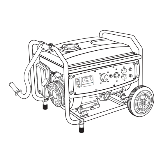
- Page 3 Fig. 1 A - Recoil starter grip (mango del arrancador retráctil) K - Oil drainage bolt (perno de drenaje de aceite) B - Air filter (filtro de aire) L - Oil cap/dipstick (tapa de relleno de aceite/varilla medidora de aceite) C - Choke lever (palanca del anegador) M - Handle (mango) D - Fuel cap (tapa del tanque)
- Page 4 Fig. 7 Fig. 4 Fig. 10 A - Oil cap/dipstick (tapa de relleno de aceite/ A - Wheel (rueda) varilla medidora de aceite) B - Lock nut (tuerca de bloqueo) B - Lubricant fill hole (agujero de llenado de C - Bolt (perno) aceite) D - Wheel mounting hole (agujero para rueda) E - Spacer (espaciador)
- Page 5 Fig. 18 Fig. 13 Fig. 16 A - Select button (botón de selección) Fig. 14 A - Fuel line (conducto de combustible) B - Fuel valve (válvula de combustible) A - Spark plug (bujía) C - Petcock (llave de purga) B - Spark plug cap (tapa de la bujía) D - Off (apagado) Fig.
-
Page 6: Table Of Contents
TABLE OF CONTENTS Introduction ..................................2 Important Safety Instructions .............................3-4 Specific Safety Rules ..............................4 Symbols ..................................5-7 Electrical ..................................8-9 Features ..................................10 Assembly ................................11-12 Operation ................................13-15 Maintenance ................................16-18 Troubleshooting ................................19 ... -
Page 7: Important Safety Instructions
IMPORTANT SAFETY INSTRUCTIONS Do not allow children or untrained individuals to use this unit. DANGER: Never start or run the engine inside a closed or partially Carbon Monoxide. Using a generator indoors CAN KILL enclosed area. Breathing exhaust fumes will kill you. YOU IN MINUTES. -
Page 8: Specific Safety Rules
IMPORTANT SAFETY INSTRUCTIONS Use only authorized replacement parts and accessories Maintain the unit per maintenance instructions in this and follow instructions in the Maintenance section of this Operator’s Manual. manual. Use of unauthorized parts or failure to follow ... -
Page 9: Symbols
SYMBOLS The following signal words and meanings are intended to explain the levels of risk associated with this product. SYMBOL SIGNAL MEANING Indicates an imminently hazardous situation, which, if not avoided, will result DANGER: in death or serious injury. Indicates a potentially hazardous situation, which, if not avoided, could result WARNING: in death or serious injury. - Page 10 SYMBOLS Some of the following symbols may be used on this product. Please study them and learn their meaning. Proper interpretation of these symbols will allow you to operate the product better and safer. SYMBOL NAME DESIGNATION/EXPLANATION Volts Voltage Amperes Current Hertz Frequency (cycles per second)
- Page 11 SYMBOLS FUEL WARNING No smoking when filling with gasoline. Do not overfill. Full level is 1 in. below the top of the fuel neck. Stop the en- gine for five minutes before refueling to avoid the heat from the muffler igniting fuel vapors.
-
Page 12: Electrical
ELECTRICAL EXTENSION CORD CABLE SIZE Refer to the table below to ensure the cable size of the extension cords you use are capable of carrying the required load. Inadequate size cables can cause a voltage drop, which can damage the appliance and overheat the cord. Load in Watts Maximum Allowable Cord Length Current in... - Page 13 ELECTRICAL GENERATOR CAPACITY POWER MANAGEMENT To prolong the life of the generator and attached devices, Make sure the generator can supply enough continuous (run- ning) and surge (starting) watts for the items you will power it is important to take care when adding electrical loads to the generator.
-
Page 14: Features
FEATURES PRODUCT SPECIFICATIONS ENGINE GENERATOR Rated Voltage ..............120V Engine Type ............212 cc OHV Rated Amps ...............30.4 A Cooling System ...........Forced Air Rated Running Watts* ..........3,650 W Rated Starting Watts ..........4,550 W Starting System ............Recoil Rated Frequency ............60 Hz Ignition System ............T.C.I. DIMENSIONS Spark Plug ............ -
Page 15: Assembly
ASSEMBLY LOOSE PARTS LIST UNPACKING See Figure 2. This product requires assembly. The following items are included with the generator: Carefully cut the box down the sides then remove the machine and any accessories from the box. Make sure Description Qty. - Page 16 ASSEMBLY ATTACHING THE HANDLE ASSEMBLY Slide bolt through the wheel spacer, then through the wheel mounting hole on the frame. See Figure 6. Install nut on bolt and tighten securely. Locate the following items: NOTE: Be careful not to overtighten so that foot mate- Handle rial collapses.
-
Page 17: Operation
OPERATION APPLICATIONS DANGER: This generator is designed to supply electrical power for Carbon Monoxide. Using a generator indoors CAN KILL operating compatible electrical lighting, appliances, tools, YOU IN MINUTES. and motor loads. Generator exhaust contains high levels of carbon mon- BEFORE OPERATING THE UNIT oxide (CO), a poisonous gas you cannot see or smell. - Page 18 OPERATION Mix fuel stabilizer and gasoline prior to filling the tank CAUTION: by using a gas can or other approved fuel container and On a level surface with the engine off, check the lubricant shaking gently to combine. level before each use of the generator. NOTE: To control the amount of fuel stabilizer being added to the engine, always mix fuel stabilizer with gasoline STARTING THE ENGINE...
- Page 19 OPERATION HIGH ALTITUDE OPERATION To cycle through these displays, press the select button. The (information type) on the digital display will light in sequence The fuel system on this engine may be influenced by opera- to show which type of information is being displayed. tion at higher altitudes.
-
Page 20: Maintenance
MAINTENANCE Replace the air filter. WARNING: Replace the air filter cover and tighten knob to secure. When servicing, use only identical replacement parts. NOTE: Do not run the generator without the air filter or Use of any other parts could create a hazard or cause gasket. - Page 21 MAINTENANCE CLEANING THE EXHAUST PORT AND DRAINING THE CARBURETOR MUFFLER Turn the engine switch OFF. Turn the fuel valve to the OFF position. Depending on the type of fuel used, the type and amount of lubricant used, and/or your operating conditions, the exhaust ...
- Page 22 MAINTENANCE STORAGE When preparing the generator for storage, allow the unit to cool completely then follow the guidelines below. STORAGE PRIOR TO STORING TIME Less than 2 Drain gasoline from tank and dispose of in a suitable container according to state and local ordinances. months 2 months to 1 ...
-
Page 23: Troubleshooting
TROUBLESHOOTING PROBLEM POSSIBLE CAUSE SOLUTION Engine will not start. Engine switch is OFF. Turn engine switch to ON. No fuel. Fill fuel tank. Lubricant level is low. Check engine lubricant level and fill, if necessary. Fuel valve is OFF. Turn fuel valve ON. Spark plug faulty, fouled, or improperly Replace spark plug. -
Page 24: Warranty
LIMITED WARRANTY WARRANTY COVERAGE OWT Industries, Inc., (the Company) warrants to the original retail purchaser that this Black Max Product is free from defects in material and workmanship and agrees to repair or replace, at the Company’s sole discretion, any defective Product free of charge within these time periods from the date of purchase: ... - Page 25 WARRANTY LIMITED ENGINE WARRANTY CHONGQING RATO POWER CO., LTD. (herein “Rato”), 4. Dirt or grit related wear caused by improper air warrants that each new engine sold by it will be free, cleaner maintenance (most often resulting in worn under normal use and service, from defects in material piston, piston rings, cylinders, valves, valve guides, and workmanship for a period listed below from the date carburetor, or other internal compo nents).
- Page 26 WARRANTY I. CALIFORNIA AND FEDERAL EMISSION CONTROL WARRANTY STATEMENT YOUR WARRANTY RIGHTS AND OBLIGATIONS The California Air Resources Board (CARB) and the United States Environmental (1) Designed, built and equipped so as to conform with all applicable regulations Protection Agency (EPA), together with CHONGQING RATO POWER CO., LTD. are adopted by the EPA and CARB pursuant to their respective authority, and pleased to explain the Emission Control System Warranty on your new small off-road (2) Free from defects in materials and workmanship which, at any time during the...
- Page 27 ÍNDICE DE CONTENIDO Introducción ................................... 2 Instrucciones de seguridad importantes ........................3-4 Reglas de seguridad específicas ........................... 4 Símbolos ..................................5-7 Aspectos eléctricos ..............................8-9 Características ................................10 Armado ...................................11-12 Funcionamiento ..............................13-15 Mantenimiento ................................16-18 ...
-
Page 28: Instrucciones De Seguridad Importantes
INSTRUCCIONES DE SEGURIDAD IMPORTANTES Mantenga a todos los circunstantes, niños y animales por lo menos a 3 m (10 pies) de distancia. PELIGRO: Use botas o zapatos robustos y secos. No utilice la unidad Monóxido de carbono. Usar un generador en el interior LO estando descalzo. -
Page 29: Reglas De Seguridad Específicas
INSTRUCCIONES DE SEGURIDAD IMPORTANTES Use únicamente repuestos y accesorios autorizados y siga las Mantenga la unidad según las instrucciones de mantenimiento instrucciones descritas en la sección de Mantenimiento de este señaladas en este manual del operador. manual. El empleo de piezas no autorizadas o el incumplimiento ... -
Page 30: Símbolos
SÍMBOLOS Las siguientes palabras de señalización y sus significados tienen el objeto de explicar los niveles de riesgo relacionados con este producto. SÍMBOLO SEÑAL SIGNIFICADO Indica una situación peligrosa inminente, la cual, si no se evita, causará PELIGRO: lesiones graves o mortales. Indica una situación peligrosa posible, la cual, si no se evita, podría causar ADVERTENCIA: lesiones graves o mortales. - Page 31 SÍMBOLOS Es posible que se empleen en este producto algunos de los siguientes símbolos. Le suplicamos estudiarlos y aprender su significado. Una correcta interpretación de estos símbolos le permitirá utilizar mejor y de manera más segura el producto. SÍMBOLO NOMBRE DENOMINACIÓN / EXPLICACIÓN Voltios Voltaje...
- Page 32 SÍMBOLOS ADVERTENCIA DE COMBUSTIBLE No fume al abastecer el combustible. No llene de más. El nivel de lleno es 25 mm (1 pulg.) debajo del cuello del tanque de combustible. Pare la marcha del motor cinco minutos antes del reabastecimiento de combustible para evitar que el calor del silenciador encienda los vapores de combustible.
-
Page 33: Aspectos Eléctricos
ASPECTOS ELÉCTRICOS CALIBRE DEL CORDÓN DE EXTENSIÓN Consulte el cuadro mostrado abajo para asegurarse de que el calibre de los cordones de extensión que utilice puedan con la carga eléctrica requerida. Los cordones de calibre insuficiente pueden causar una caída de voltaje, lo cual puede quemar el dispositivo y recalentar el cordón mismo. - Page 34 ASPECTOS ELÉCTRICOS CAPACIDAD DEL GENERADOR 1. Sin equipos conectados al generador, ponga en marcha el motor de la manera que se describe posteriormente en este manual. Cerciórese que el generador pueda suministrar suficientes vatios 2. Enchufe y active la primera carga, preferiblemente la máxima de potencia continua (en marcha) y de sobrecorriente (al arrancar) carga que tenga.
-
Page 35: Características
CARACTERÍSTICAS ESPECIFICACIONES DEL PRODUCTO GENERADOR MOTOR Voltaje nominal ............120V Tipo de motor ..........212 cc, OHV Amperaje nominal............30,4 A Sistema de enfriamiento........Aire forzado Potencia nominal en marcha en vatios* ....3 650 W Potencia nominal en arranque en vatios ....4 550 W Sistema de arranque ..........Retráctil Frecuencia nominal ............60 Hz Sistema de ignición .............T.C.I. -
Page 36: Armado
ARMADO DESEMPAQUETADO LISTA DE PIEZAS SUELTAS Vea la figura 2. Este producto requiere armarse. Los siguientes accesorios vienen incluidos: Corte cuidadosamente los lados de la caja y después retire la herramienta y cualesquier accesorios de la caja. Núm. Asegúrese de que estén presentes todos los artículos ref. - Page 37 ARMADO COLOCACIÓN DEL MANGO Coloque un espaciador de rueda en el centro de ésta. Deslice el perno a través del espaciador de rueda y a Vea la figura 6. través del agujero de montaje de la rueda. Localice los siguientes artículos: Coloque la tuerca en el perno y ajústela correctamente.
-
Page 38: Funcionamiento
FUNCIONAMIENTO Antes de cada uso, inspeccione todo el producto para detectar algún daño, partes faltantes o sueltas, como tornillos, PELIGRO: tuercas, pernos, tapas, etc. Ajuste firmemente todos los Monóxido de carbono. Usar un generador en el interior sujetadores y las tapas y no active este producto hasta que LO MATARÁ... - Page 39 FUNCIONAMIENTO Limpie la varilla de nivel y vuelva a asentarla en el agujero; VERIFICACIÓN Y ABASTECIMIENTO DE no la enrosque. COMBUSTIBLE Retire de nuevo la varilla medidora de lubricante y verifique Vea la figura 8. el nivel de lubricante. El nivel de lubricante siempre debe estar entre las áreas cubierta con rayas entrecruzadas de ADVERTENCIA: la varilla medidora.
- Page 40 FUNCIONAMIENTO Horómetro: El contador de horas lleva la cuenta de las horas Tire del mango del arrancador retráctil hasta que comience a funcionar el motor (seis veces como máximo). que el motor ha estado en marcha desde la última vez que se lo encendió...
-
Page 41: Mantenimiento
MANTENIMIENTO NOTA: No ponga a funcionar el generador sin los filtro de ADVERTENCIA: aire o junta. Se causa un desgaste acelerado del motor. Al dar servicio a la unidad, sólo utilice piezas de repuesto CAMBIO DEL LUBRICANTE DEL MOTOR idénticas. El empleo de piezas diferentes podría causar Vea la figura 15. - Page 42 MANTENIMIENTO LIMPIEZA DEL ORIFICIO DE ESCAPE Y DEL DRENAJE DEL CARBURADOR SILENCIADOR Ponga el interruptor del motor en OFF (APAGADO). Según sea el tipo de combustible empleado, el tipo y Ponga la válvula de combustible en la posición OFF cantidad de lubricante empleado, así...
- Page 43 MANTENIMIENTO ALMACENAMIENTO Al preparar el generador para guardarlo, deje que la unidad se enfríe por completo y luego siga los lineamientos señalados abajo. TIEMPO DE ANTES DE GUARDARLO ALMACENAMIENTO Menos de dos meses Vacíe el tanque de combustible y colóquelo en un recipiente apropiado según lo establecido por las disposiciones estatales y locales.
-
Page 44: Corrección De Problemas
CORRECCIÓN DE PROBLEMAS PROBLEMA CAUSA POSIBLE SOLUCIÓN El motor no arranca. El interruptor del motor está en Ponga el interruptor del motor en apagado (OFF). encendido (ON). No hay combustible. Llene el tanque de combustible. Está bajo el nivel de lubricante. Revise el nivel del lubricante del motor, y reabastézcalo si es necesario. -
Page 45: Garantía
GARANTÍA GARANTIA LIMITADA COBERTURA DE LA GARANTÍA OWT Industries, Inc., (la Compañía) garantiza al comprador minorista original que este Producto BlackMax carece de defectos en material y mano de obra, y acuerda reparar o reemplazar, a la entera discreción de la Compañía, cualquier Producto defectuoso sin cargo en los siguientes períodos a partir de la fecha de la compra: Dos años si el Producto se utiliza exclusivamente para fines personales, familiares o domésticos. - Page 46 GARANTÍA GARANTÍA LIMITADA DE MOTOR CHONGQING RATO POWER CO., LTD., (a quien en este 4. El desgaste relacionado con la suciedad o mugre documento se le llamará “Rato”), garantiza que cada nuevo causado por el mantenimiento insuficiente del filtro de motor que venda estará, en condiciones de uso y servicio aire (que a menudo resulta en desgastes prematuros en normales, exento de defectos en materiales y mano de obra...
- Page 47 GARANTÍA DECLARACIÓN DE GARANTÍA FEDERAL Y DEL ESTADO DE CALIFORNIA SOBRE EL CONTROL DE EMISIONES SUS DERECHOS Y OBLIGACIONES RELACIONADOS CON LA GARANTÍA La Junta de Recursos del Aire de California (California Air Resources Board, CARB) y la (b) Cobertura general de la garantía sobre el control de emisiones: CHONGQING RATO Agencia de Protección Ambiental (Environmental Protection Agency, EPA) de los Estados POWER CO., LTD.
- Page 48 MANUAL DEL OPERADOR BM903655RB CALIFORNIA PROPOSITION 65 SERVICE For parts or service, contact your nearest Black Max authorized WARNING: service dealer. Be sure to provide all relevant information when This product and substances that may become airborne from its use may con- you call or visit.