Table of Contents
Advertisement
Available languages
Available languages
Quick Links
English
Français
WARNING
READ YOUR INSTRUCTIONS COMPLETELY AND CAREFULLY BEFORE ATTEMPTING TO SET UP YOUR
CAB OR OPERATE YOUR SNOW THROWER WITH YOUR NEW CAB INSTALLED.
Ariens Sno-Thro and Ariens are registered trademarks of the Ariens Company.
Questions, problems, missing parts? Before returning to your retailer, call
customer service at 1-800-854-2315, 7:30 a.m. - 4 p.m., PST, Monday-Friday.
Email: customerservice@classicaccessories.com
(page 01)
(page 13)
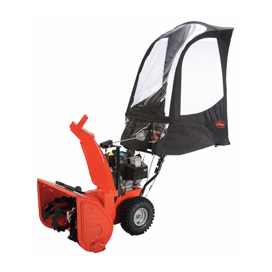
ITEM/ARTICLE: 72102600, 72102600-SC
SNO-THRO
CAB KIT
®
21cH54_22890
Advertisement
Table of Contents

Related Manuals for Ariens SNO-THRO CAB KIT


Summary of Contents for Ariens SNO-THRO CAB KIT
- Page 1 READ YOUR INSTRUCTIONS COMPLETELY AND CAREFULLY BEFORE ATTEMPTING TO SET UP YOUR CAB OR OPERATE YOUR SNOW THROWER WITH YOUR NEW CAB INSTALLED. Ariens Sno-Thro and Ariens are registered trademarks of the Ariens Company. Questions, problems, missing parts? Before returning to your retailer, call customer service at 1-800-854-2315, 7:30 a.m.
-
Page 2: Safety Information
TABLE OF CONTENTS Safety Information ....................................2 Package Contents List (Parts and Hardware) ............................3 Tools Needed ......................................3 Assembly Time ......................................3 Assembly Instructions ..................................4-11 Care and Maintenance .....................................12 Troubleshooting ......................................12 Warranty .........................................12 Replacement Parts ....................................12 SAFETY INFORMATION Please read and understand this entire manual before •... -
Page 3: Tools Needed
PACKAGE CONTENTS LIST (PARTS) START ASSEMBLY ON PAGE 4 M8 X 30 HEX BOLT M8 X 30 HEX BOLT M8 WASHER M8 WASHER ALSO INCLUDED FOR 72102600-SC: Snow cab square tube clamp adaptor kit & instructions 52423400 SPRING CLIP SPRING CLIP INSTALLED AT FACTORY INSTALLED AT FACTORY Part... -
Page 4: Parts Needed
STEP 1 ASSEMBLE THE FRAME (FIG. 1-3) Note: Assemble frame on a clean flat surface next to your snow thrower for easy mounting. PARTS NEEDED TOOLS NEEDED NONE Insert the center mounting bar [A] onto the stub tube of the right mounting Slide the mounting bar end [D] onto the end of the right mounting bar [B]. - Page 5 STEP 2 ASSEMBLE THE BACK HOOP FRAME (FIG. 1-6) Note: It may help to place the parts flat on the ground for easier assembly. Note: The back hoop side and corner poles [F and G] each have clear plastic sleeves on one end. The frame hoop top pole [H] DOES NOT have clear plastic sleeves.
- Page 6 STEP 3 ASSEMBLE THE FRONT POLE (FIG. 1-3) WARNING: Use care when assembling the front hoop side and top poles. Poles under tension can slip out of the metal/plastic sleeves causing serious injury. Safety goggles are recommended. PARTS NEEDED TOOLS NEEDED NONE Insert one front hoop side pole [I] into another and then into the front hoop top pole [J].
- Page 7 STEP 4 INSTALL MOUNTING POST (FIG. 1-2) PARTS NEEDED TOOLS NEEDED 1/2 in. Box Wrench Adjustable Wrench 1/2 in. Socket Wrench Assemble the mounting post upper clamp [K] to the top plate [L] on the outer edge of Repeat with the remaining mounting the frame [C].
- Page 8 STEP 5 INSTALL THE CAB FABRIC SHELL ONTO THE FRAME (FIG. 1-5) Note: Fabric shell will be tight when properly assembled. PARTS NEEDED TOOLS NEEDED NONE Slide the pocket in the top of Pull the shell fabric to the back to Slide the front elastic strap at the the fabric shell [V] over the secure the elastic strap at the back...
- Page 9 STEP 6 ATTACH THE MOUNTING SYSTEM TO YOUR SNOW THROWER (FIG. 1-4) Note: Exact positioning may vary depending on your machine. Note: In some instances, it may be necessary to mount the top U-bolts [P] above the handlebar crossbar support. This will help the assembled cab sit higher for added clearance.
- Page 10 STEP 7 INSTALL ASSEMBLED CAB ON LOWER MOUNTING POSTS (FIG. 1-2) PARTS NEEDED Side of Snow Cab shell pulled aside for visibility Note: It may be necessary to adjust the position of the lower mounting posts [M, N] in order to slide upper mounting posts [K] into them.
- Page 11 STEP 8 ADJUSTING SNOW THROWER CAB ANGLE (FIG. 1) CAUTION: No part of the fabric cab skin should touch the engine or exhaust system of your snow thrower. PARTS NEEDED TOOLS NEEDED NONE 1/2 in. Box Wrench Adjustable Wrench 1/2 in. Socket Wrench Adjust for best visibility, weather...
-
Page 12: Troubleshooting
CARE AND MAINTENANCE STORAGE Store in a clean dry place. Never store a wet cab in an enclosed area as it can develop mildew. Avoid folding the plastic windows of the cab for long periods. BOLTS Check all bolts before each use to see that they are tight. If one or more bolts come loose, failure of cab parts may occur. WINDOWS Don't clean the plastic windows when they are dry—you can scratch them. - Page 13 ITEM/ARTICLE: 72102600, 72102600-SC CABINE SNO-THRO ® English (page 01) Français (page 13) AVERTISSEMENT VEUILLEZ LIRE COMPLÈTEMENT ET ATTENTIVEMENT LES INSTRUCTIONS AVANT DE COMMENCER À INSTALLER VOTRE NOUVELLE CABINE OU D’UTILISER VOTRE SOUFFLEUSE À NEIGE APRÈS AVOIR INSTALLÉ LA CABINE. Vous avez des questions, des problèmes ou des pièces s’avèrent manquantes? Avant de retourner au détaillant, veuillez consulter le site classicaccessories.com ou appelez le service à...
-
Page 14: Consignes De Sécurité
TABLE DES MATIÈRES Consignes de sécurité .....................................14 Contenu de la boîte (pièces et quincaillerie) ............................15 Outils nécessaires ....................................15 Temps d’assemblage ....................................15 Instructions d’assemblage ................................16-23 Nettoyage et entretien ................................... 24 Guide de dépannage ....................................24 Garantie ......................................... 24 Pièces de rechange ....................................24 CONSIGNES DE SÉCURITÉ... - Page 15 CONTENU DE LA BOÎTE (PIÈCES ) COMMENCER L'ASSEMBLAGE À LA PAGE 16 M8 X 30 HEX BOLT M8 X 30 HEX BOLT M8 WASHER M8 WASHER ARTICLES ÉGALEMENT COMPRIS POUR 72102600-SC : nécessaire de fixation pour cabine de protection contre la neige avec tubes carrés. 52423400 Pièce Description...
-
Page 16: Pièces Nécessaires
ÉTAPE 1 ASSEMBLER LE CADRE (VOIR ILLUSTRATIONS 1 À 3) Remarque: Pour faciliter le montage, assemblez le cadre sur une surface plane propre à côté de votre souffleuse à neige. PIÈCES NÉCESSAIRES OUTILS NÉCESSAIRES AUCUN Glissez la barre de montage centrale [A] sur le goujon de la barre de montage droite [B] Glissez la pièce d’extrémité... - Page 17 ÉTAPE 2 ASSEMBLER L’ARCEAU ARRIÈRE (VOIR ILLUSTRATIONS 1 À 6) Remarque: Nous vous recommandons de placer ces pièces à plat sur le sol afin de faciliter l’assemblage. Remarque: Les tiges latérales et des coins de l’arceau arrière [E et F] possèdent chacune des manchons en plastique transparent au niveau de leur extrémité.
- Page 18 ÉTAPE 3 ASSEMBLER L’ARCEAU AVANT (VOIR ILLUSTRATIONS 1 À 3) AVERTISSEMENT: Faites attention lorsque vous assemblez les tiges de l’arceau avant et les tiges supérieures. Les tiges tendues risquent de glisser hors des manchons en métal ou plastique et de gravement vous blesser. Il est recommandé de porter des lunettes de protection.
- Page 19 ÉTAPE 4 INSTALLER LE MONTANT DE FIXATION (VOIR ILLUSTRATIONS 1 À 6) PIÈCES NÉCESSAIRES OUTILS NÉCESSAIRES Clé polygonale de 1/2 po. Clé à molette de 1/2 po. Clé à douilles de 1/2 po. Fixez le support de la bride du montant de fixation [K] à la partie supérieure de la bride Répétez l’opération avec le [L] sur le bord extérieur du cadre [C].
- Page 20 ÉTAPE 5 INSTALLER LA TOILE DE LA CABINE SUR LE CADRE (VOIR ILLUSTRATIONS 1 À 5) Remarque: La toile sera tendue une fois que le cadre est correctement monté. PIÈCES NÉCESSAIRES OUTILS NÉCESSAIRES AUCUN Insérez avec précaution la partie Saisissez le coin arrière inférieur de la Faites passer l’élastique avant situé...
- Page 21 ÉTAPE 6 FIXER LE DISPOSITIF DE MONTAGE SUR LA SOUFFLEUSE À NEIGE (VOIR ILLUSTRATIONS 1 À 4) Remarque: La position exacte risque de varier selon le fabricant de la souffleuse à neige. Remarque: Dans certains cas, il peut s’avérer nécessaire d’installer les étriers filetés supérieurs [P] au-dessus de la barre du support du guidon.
- Page 22 ÉTAPE 7 INSTALLER LA CABINE ASSEMBLÉE SUR LES MONTANTS DE FIXATION INFÉRIEURS (VOIR ILLUSTRATIONS 1 À 2) PIÈCES NÉCESSAIRES La paroi latérale de la cabine a été tirée sur le côté pour plus de clarté Note : Il pourra s’avérer nécessaire de modifier la position des montants de fixation inferieurs [M et N] afin d’y glisser les montants de fixation supérieurs [K].
- Page 23 ÉTAPE 8 RÉGLER L'ANGLE D'INCLINAISON DE LA CABINE (VOIR ILLUSTRATION 1) ATTENTION: Aucune partie de la toile de la cabine ne doit toucher le moteur ou le système d’échappement de la souffleuse à neige. PIÈCES NÉCESSAIRES OUTILS NÉCESSAIRES AUCUNE Clé polygonale de 1/2 po.
-
Page 24: Guide De Dépannage
NETTOYAGE ET ENTRETIEN REMISAGE Remisez la cabine dans un endroit propre et sec. Ne rangez jamais une cabine mouillée dans un espace clos car elle risque de moisir. Évitez de plier les fenêtres en plastique de la cabine et de les laisser ainsi pendant de longues périodes. BOULONS Assurez-vous que les boulons sont tous correctement serrés à...