Table of Contents
Advertisement
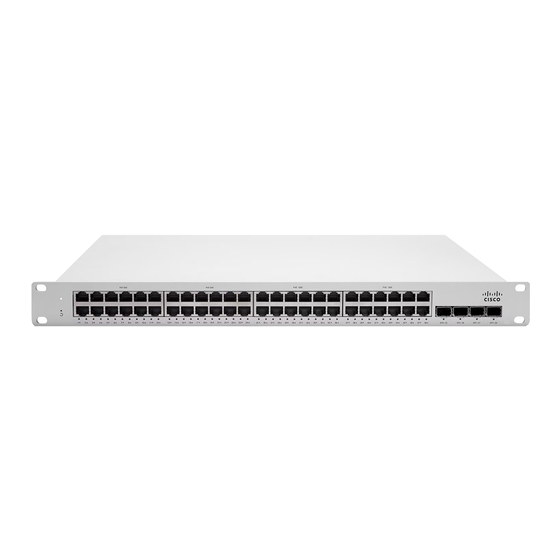
MS250 Series Installation Guide
About this Guide
This guide provides instruction on how to install and configure your MS250 series switch. This guide also provides mounting instructions and limited
troubleshooting procedures. For more switch installation guides, refer to the
Model number
MS250-24
Stackable Layer-3 24-port gigabit Ethernet switch with 4 SFP+ interfaces, hot-swappable power supplies
MS250-24P
Stackable Layer-3 24-port gigabit Ethernet 370W PoE switch with 4 SFP+ interfaces, hot-swappable power supplies
MS250-48
Stackable Layer-3 48-port gigabit Ethernet switch with 4 SFP+ interfaces, hot-swappable power supplies
MS250-48LP
Stackable Layer-3 48-port gigabit Ethernet 370W PoE switch with 4 SFP+ interfaces, hot-swappable power supplies
MS250-48FP
Stackable Layer-3 48-port gigabit Ethernet 740W PoE switch with 4 SFP+ interfaces, hot-swappable power supplies
Product Overview
Physical Specifications
1GbE RJ45
10GbE SFP+
Hardware Stack Port
Dedicated Mgmt Interface
PoE/PoE+ Capable
Hot Swap Power Supply
switch installation guides section
Description
MS250-24
24
4
2
1
-
Yes, Dual
on our documentation website.
MS250-24P
24
4
2
1
Yes, 370W
Yes, Dual
MS250-48
48
4
2
1
-
Yes, Dual
1
Advertisement
Table of Contents

Related Manuals for Cisco Meraki MS250 Series


Summary of Contents for Cisco Meraki MS250 Series
- Page 1 MS250 Series Installation Guide About this Guide This guide provides instruction on how to install and configure your MS250 series switch. This guide also provides mounting instructions and limited troubleshooting procedures. For more switch installation guides, refer to the switch installation guides section on our documentation website.
- Page 2 Optional Power Supply 2 x 250W 2 x 640W 2 x 250W Fan Operation Fixed Internal Fixed Internal Fixed Internal Power Input 100 - 240 VAC, 47-63 Hz 100 - 240 VAC, 47-63 Hz 100 - 240 VAC, 47-63 Hz 15 - 882 W 15 - 882 W 15 - 882 W...
- Page 3 Ports and Status Indicators The MS uses LEDs to inform the user of the device's status. When the device powers on, all the Internet LEDs flash twice. Additional functions are described below, from left to right. Front Panel Components Item Function LED Status Meaning...
- Page 4 No link is detected Redundant Power Supplies Green Active and functio Power cords may be ordered separately. Equipment is to be used only in a restricted access location and installed/operated only by trained service personnel. Package contents In addition to the MS switch, the following are provided: Rack Mount Kit includes: ▪...
-
Page 5: Pre-Install Preparation
source. • Before you work on any equipment, be aware of the hazards involved with electrical circuitry and be familiar with standard practices for preventing accidents. • Read the mounting instructions carefully before beginning installation. Failure to use the correct hardware or to follow the correct procedures could result in a hazardous situation to people and damage to the system. -
Page 6: Installation Instructions
Dynamic Assignment When using DHCP, the DHCP server should be configured to assign a static IP address for each MAC address belonging to a Meraki switch. Other features of the network, such as 802.1X authentication, may rely on the property that the switches have static IP addresses. Static Assignment Static IPs are assigned using the local web server on each switch. - Page 7 2. Attach the switch face plate to the cage nuts on the rack.
- Page 8 3. Insert the power supply unit into the back of the switch. After it has been securely installed, you can connect power to the power supply unit.
-
Page 9: Basic Troubleshooting
Troubleshooting an MS Switch Reference https://documentation.meraki.com/MS for additional information and troubleshooting tips. If you are still experiencing hardware issues, please contact Cisco Meraki support by logging in to dashboard and using the Help option near the top of the page,... -
Page 10: Bringing Your Stack Online
Meraki data sheets. If your Cisco Meraki device fails and the problem cannot be resolved by troubleshooting, contact support to address the issue. Once support determines that the device is in a failed state, they can process an RMA and send out a replacement device free of charge. In most circumstances, the RMA will include a pre-paid shipping label so the faulty equipment can be returned. - Page 11 • Rules and conditions for the sale of equipment are determined by the terms of contracts concluded by Cisco or authorized Cisco partners with equipment buyers. • Disposal of a technical device at the end of its service life should be carried out in accordance with the requirements of all state regulations and laws.