Table of Contents
Advertisement
Quick Links
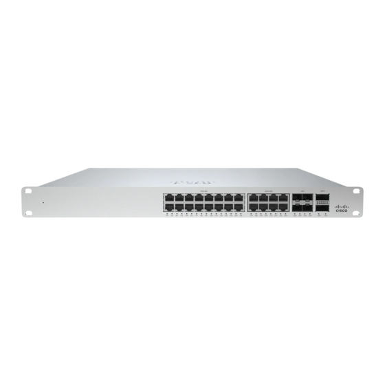
MS355 Series Installation Guide
About this Guide
This guide provides instruction on how to install and configure your MS355 series switch. This guide also provides
mounting instructions and limited troubleshooting procedures. For more switch installation guides, refer to the
switch installation guides section
Product Overview
Physical Specifications
1Gbe RJ45
mGbe RJ45
10Gbe SFP+
40Gbe QSFP+
100G Hardware
Stack Port
Dedicated
Mgmt Interface
UPoE Capable
Hot Swap Power
Supply
Hot Swap Fans
Power Input
on our documentation website.
MS355-24X
MS355-24X2
16
-
8
24
4
4
2
2
2
2
1
1
Yes, 740W
Yes, 740W
Yes, Dual
Yes, Dual
Yes, 3x
Yes, 3x
100 - 240 VAC, 47-63
100 - 240 VAC, 47-63
MS355-48X
MS355-48X2
32
24
16
24
4
4
2
2
2
2
1
1
Yes, 740W
Yes, 740W
Yes, Dual
Yes, Dual
Yes, 3x
Yes, 3x
100 - 240 VAC, 47-63
100 - 240 VAC, 47-63
Hz
Hz
1
Advertisement
Table of Contents

Related Manuals for Cisco MERAKI MS355 Series


Summary of Contents for Cisco MERAKI MS355 Series
- Page 1 MS355 Series Installation Guide About this Guide This guide provides instruction on how to install and configure your MS355 series switch. This guide also provides mounting instructions and limited troubleshooting procedures. For more switch installation guides, refer to the switch installation guides section on our documentation website.
- Page 2 Power 110 - 1793W 110 - 1793W 110 - 1793W 110 - 1793W Consumption Operating 32°F - 113 °F 32°F - 113 °F 32°F - 113 °F 32°F - 113 °F Temperature 0°C - 45°C 0°C - 45°C 0°C - 45°C 0°C - 45°C -4°F - 158°F -4°F - 158°F...
- Page 3 Ports and Status Indicators The MS uses LEDs to inform the user of the device's status. When the device powers on, all the Internet LEDs flash twice. Additional functions are described below, from left to right. Front Panel Components Item Function LED Status Meaning...
-
Page 4: Package Contents
Back Panel Components Item Function Meaning Status Restore button to clear switch IP and local configuration Restore settings Management Interface Green Connected, used for easy access to the local status page Stack Ports Stack Cables are connected here Redundant Fans Green Active and operational Redundant Power... -
Page 5: Safety And Warnings
◦ INTL M6 mounting screws and cage nuts, 10 of each ◦ Mounting washers ◦ 2 Rack mount rails ◦ Rail kit screws • 1025WAC Power Supply Unit • 3 Pre-installed Fans Safety and Warnings These operations are to be taken with respect to all local laws. Please take the following into consideration for safe operation: •... -
Page 6: Assigning An Ip Address
Check and Set Firmware To ensure your switch performs optimally immediately following installation, it is recommended that you facilitate a firmware upgrade prior to mounting your switch. 1. Attach your switch to power and a wired Internet connection. 2. The switch will turn on and the power LED will glow solid orange. 3. -
Page 7: Installation Instructions
Static IP via DHCP Reservations Instead of associating to each Meraki switch individually to configure static IP addresses, an administrator can assign static IP addresses on the upstream DHCP server. Through “DHCP reservations,” IP addresses are “reserved” for the MAC addresses of the Meraki switches. Please consult the documentation for the DHCP server to configure DHCP reservations. - Page 8 3. Attach the rack mount rail to the sides of the switch. 4. Insert the rack mount rail into the rack mount rail channel.
- Page 9 5. Attach the switch face plate to the cage nuts on the rack. 6. Secure the rack mount rail to the rack mount rail channel.
-
Page 10: Basic Troubleshooting
7. Insert the power supply unit into the back of the switch. After it has been securely installed, you can connect power to the power supply unit. 8. (Optional) Install additional SFP+, QSFP+ or QSFP28 units as needed, depending on the compatibility of your model. Basic Troubleshooting The following steps can be used for troubleshooting basic connectivity issues with your switch. -
Page 11: Bringing Your Stack Online
If you are still experiencing hardware issues, please contact Cisco Meraki support by logging in to dashboard and using the Help option near the top of the page, then opening and email case or calling using the contact information on that page. - Page 12 • The equipment is subject to installation and maintenance by specialists with the appropriate qualifications, sufficient specialized knowledge, and skills. • Rules and conditions for the sale of equipment are determined by the terms of contracts concluded by Cisco or authorized Cisco partners with equipment buyers.