Advertisement
MS210 Series Installation Guide
About this Guide
This guide provides instruction on how to install and configure your MS210 series switch. This guide also provides
mounting instructions and limited troubleshooting procedures. For more switch installation guides, refer to the
switch installation guides section
Model number
MS210-24
Stackable Layer-2 24-port gigabit Ethernet switch with 4 SFP interfaces
Stackable Layer-2 24-port gigabit Ethernet 370W PoE switch with 4 SFP
MS21024P
interfaces
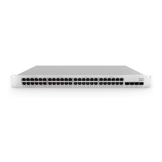
MS210-48
Stackable Layer-2 48-port gigabit Ethernet switch with 4 SFP interfaces
Stackable Layer-2 48-port gigabit Ethernet 370W PoE switch with 4 SFP
MS210-48LP
interfaces
Stackable Layer-2 48-port gigabit Ethernet 740W PoE switch with 4 SFP
MS210-48FP
interfaces
Product Overview
Physical Specifications
on our documentation website.
Description
MS210-24
MS210-24P
MS210-48
MS210-48LP
MS2
1
Advertisement
Table of Contents

Related Manuals for Cisco Meraki MS210 Series


Summary of Contents for Cisco Meraki MS210 Series
- Page 1 MS210 Series Installation Guide About this Guide This guide provides instruction on how to install and configure your MS210 series switch. This guide also provides mounting instructions and limited troubleshooting procedures. For more switch installation guides, refer to the switch installation guides section on our documentation website.
-
Page 2: Package Contents
1GbE RJ45 10GbE SFP 10G Hardware Stack Port Dedicated Mgmt Interface PoE/PoE+ Capable Yes, 370W Yes, 370W Power Supply Fixed Internal Fixed Internal Fixed Internal Fixed Internal Fixe External RPS* External RPS* External RPS* External RPS* Exte Redundant Power Supply (optional) (optional) (optional) - Page 3 Rack Mount Kit includes: ▪ US 12-24 mounting screws and cage nuts, 5 of each ▪ INTL M5 mounting screws and cage nuts, 5 of each ▪ INTL M6 mounting screws and cage nuts, 5 of each ▪ Mounting washers Note: MS210 does not include stacking cables.
- Page 4 Front Panel Components Function LED Status Meaning Power Solid orange Switch is unable to connect to the Meraki cloud Flashing white Firmware upgrade in process Solid white Switch is fully operational and connected to the Meraki cloud Switch does not have power Restore Restore button to clear switch IP and local configuration settings Switch Ports...
- Page 5 RPS2300 Redundant Power Supply (Optional) The MS210 series supports connecting the Cisco RPS2300 for optional power redundancy. MS210 series models support failover and reversion to main power once it has been restored. The following Cisco part numbers are supported: Part number...
-
Page 6: Safety And Warnings
▪ INTL M5 mounting screws and cage nuts, 5 of each ▪ INTL M6 mounting screws and cage nuts, 5 of each ▪ Mounting washers Note: MS210 does not include stacking cables. Stacking cables sold separately. Safety and Warnings These operations are to be taken with respect to all local laws. Please take the following into consideration for safe operation: •... -
Page 7: Assigning An Ip Address
1. Attach your switch to power and a wired Internet connection. 2. The switch will turn on and the power LED will glow solid orange. 3. If the unit requires an upgrade, the power LED will begin blinking white until the upgrade is complete, at which point the LED will turn solid white. -
Page 8: Installation Instructions
Installation Instructions Note: Each switch comes with a graphical instruction pamphlet within the box. This pamphlet contains detailed step by step guides and images to assist in the physical install of the switch. 1. Install the mounting cage nuts in the rack being used for the switch. 2. - Page 9 3. Attach the rack mount rail to the sides of the switch.
- Page 10 4. Insert the rack mount rail into the rack mount rail channel.
- Page 11 5. Attach the switch face plate to the cage nuts on the rack.
- Page 12 6. Secure the rack mount rail to the rack mount rail channel.
-
Page 13: Mounting Hardware
Step 6.png 7. (Optional) Install additional SFP+ units as needed, depending on the compatibility of your model. Mounting hardware The mounting hardware includes a rack mount kit for standard 1U racks. When installing the device, make sure that there is sufficient space between the rear of the rack and other obstacles to ensure adequate airflow. Optional Mid-Mount bracket MS210 48 port models are designed for an optional MA-MNT-MID-1 mid-mount bracket when using 2-post racks. -
Page 14: Basic Troubleshooting
If you are still experiencing hardware issues, please contact Cisco Meraki support by logging in to dashboard and using the Help option near the top of the page, then opening and email case or calling using the contact information on that page. - Page 15 If your Cisco Meraki device fails and the problem cannot be resolved by troubleshooting, contact support to address the issue. Once support determines that the device is in a failed state, they can process an RMA and send out a replacement device free of charge.