
Related Manuals for York Turbomaster M Series

Summary of Contents for York Turbomaster M Series
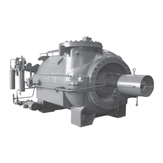
- Page 1 SERIES M TURBOMASTER COMPRESSORS INSTALLATION, OPERATION AND Supersedes: 220.11-NM1 (366) Form 220.11-NM2 (602) MAINTENANCE SERIES M TURBOMASTER COMPRESSORS 00617VIP...
- Page 2 NOT be installed inside the panel. NO external wiring is allowed to be run through the panel. All wiring must be in accordance with YORK’s pub- lished specifications and must be performed ONLY by qualified YORK personnel. YORK will not be responsible for damages/problems resulting from improper connections to the controls or application of improper control signals.
- Page 3 FORM 220.11-NM2 (602) CHANGEABILITY OF THIS DOCUMENT In complying with YORK’s policy for continuous prod- It is the responsibility of operating/service personnel uct improvement, the information contained in this as to the applicability of these documents to the equip- document is subject to change without notice. While ment in question.
- Page 4 FORM 220.11-NM2 (602) TABLE OF CONTENTS SECTION Description of System and Fundamentals of Operation ......... 7 SECTION Installation ....................11 SECTION Operation ...................... 14 SECTION Service ......................32 YORK INTERNATIONAL...
- Page 5 AOP Differential Coltrol Settings ................... 29 COP Low Oil Differential Safety Settings ..............29 Oil Pressure Switch Tubing Sizing .................. 30 Maintenance Requirements for YORK Multistage Centrifugal Compressors ....33 Compressor Tools ......................37 Shaft Seal Parts ......................39 Typical Shaft Seal Installation “Height” Dimension ............40 Clearances ........................
- Page 6 After Lifting Top Half of Compressor Casing with Sump Housing Removed ....56 Removing Interstage Labyrinth Seals ................57 Diffusers Removed ......................58 Exit Plate Removal ......................58 Removing First Stage Impeller Labyrinth Seal ..............59 Rotor ..........................59 YORK INTERNATIONAL...
- Page 7 These compressors can incorporate 1 to 8 stages of com- YORK’s Series M Turbomaster Compressors are de- pression within a single casing. Series M Turbomaster signed for compressing various refrigerants, oil field...
- Page 8 There can be on the system. variations on the internal bolting strength and sizing if YORK INTERNATIONAL...
- Page 9 FORM 220.11-NM2 (602) YORK INTERNATIONAL...
- Page 10 Certain liquids that are expelled from the system at atmospheric pressure may be capable of producing a freeze hazard to skin or eyes. Eye protection and gloves should be worn to avoid potential splash hazards. YORK INTERNATIONAL...
- Page 11 Installation Information 2. If the atmospheric shaft seal is leaking, charge the com- pressor shaft seal reservoir with the appropriate YORK Since the equipment will vary to meet the requirements oil (refer to Adding Oil to the Compressor, pages 27 of a specific installation, it is recommended that the fol- and 28) before continuing the pressure testing.
- Page 12 B. In addition to compressor, check motor speed in- the components, or finalize the adjustments of the creaser / turbine bearing temperatures carefully. base frame jackscrews. Compressors that utilize refrigerant cooled oil coolers may not be oper- ated if there is no source of coolant available. YORK INTERNATIONAL...
- Page 13 TABLE 3 – APPROXIMATE COMPONENT WEIGHTS FOR SERIES M COMPRESSORS CASING ID. GRAY IRON DUCTILE IRON STEEL (INCHES) (LBS.) (LBS.) (LBS.) PRV HOUSING 25/26 OIL SUMP HOUSING PRV HOUSING 1,230 OIL SUMP 1,715 1,715 2,165 HOUSING PRV HOUSING 2,125 2,125 2,530 OIL SUMP 3,520 3,520 4,665 HOUSING YORK INTERNATIONAL...
- Page 14 (1, 2 and 3) from shifting axially during surging and load changes. Extreme elevation of the bal- ance piston pressure is an indication of a problem that can result in failure of the thrust bearing (7). YORK INTERNATIONAL...
- Page 15 FORM 220.11-NM2 (602) YORK INTERNATIONAL...
- Page 16 Operation FORM 220.11-NM2 (602) YORK INTERNATIONAL...
- Page 17 FORM 220.11-NM2 (602) FORM 220.11-NM2 (602) LD07817 FIG. 4B – CUT-A-WAY VIEW - MODEL 255 COMPRESSOR YORK INTERNATIONAL YORK INTERNATIONAL...
- Page 18 The infor- be reduced. mation in that document should not be applied to any other application unless verified on the application data sheet. FIG. 5 – EXTERNAL SUMP VENT EQUALIZING LINES, EXTERNAL BALANCE PISTON VENT LINES YORK INTERNATIONAL YORK INTERNATIONAL...
- Page 19 PIN, INSERT 1/4" X 38" PLUG, PIPE, HEX SOC. CSK. HD. 1/4" SCREW, CAP, 12 PT. HD., OIL, PUMP PLUG, PIPE, 3/4" SQ. SOC. CSK. HD. COUPLING, YORK FLEX, COUPLING SYSTEM SHAFT, DRIVE, COUPLING SYSTEM HOUSING, OIL PUMP, 1 PC. NIPPLE, PIPE COVER, BEARING HOUSING GASKET, OIL PUMP HSG.
- Page 20 Larger diameter and 00621VIP FIG. 6 – EXPLODED VIEW OF ATMOSPHERIC SHAFT SEAL YORK INTERNATIONAL...
- Page 21 4. Atmospheric Shaft Seal (9) The oil which flows from the filter (3) to the suction The main oil pump (1) is a centrifugal type of YORK end of the compressor enters the bearing housing and design. It is bolted to and is directly driven by a hex on flows through a drilled passage to an annular space the end of the rotor shaft.
- Page 22 Operation FORM 220.11-NM2 (602) YORK INTERNATIONAL...
- Page 23 FORM 220.11-NM2 (602) LD07321 FIG. 8 – OIL PIPING SCHEMATIC FOR PARALLEL LUBRICATION SYSTEM (AFTER 1970) YORK INTERNATIONAL...
- Page 24 150°F minimum. pump differential control and stop the C. Add new oil of the proper YORK designation, if auxiliary oil pump. necessary (refer to Adding Oil to Compressor). D. Start all system auxiliaries.
- Page 25 Opening the pre-rotation vanes, as YORK designation before starting. soon as the compressor comes up to speed, will reduce the tendency of the...
- Page 26 (refer to the appli- cation data sheet). 3. If oil pressure falls, the oil filter element must be changed before the oil pressure differential falls to YORK INTERNATIONAL...
- Page 27 The Auxiliary Oil Pump (2, Figures 7 & 8) is typically lube piping systems. When adding or mounted on the side of the compressor. This pump is changing oil, use only YORK Com- automatically controlled, through the auxiliary oil pres- pressor Oil of the proper designation sure differential switch mounted on the compressor, or specified for the application.
- Page 28 Be sure the oil is relief valve higher to charge oil. Alternatively, the proper YORK designation for the application. use the YORK Hand Oil Pump (P/N 470- 5. Connect the pump discharge connection to the oil 10654) to add oil through the drain valve.
- Page 29 COMPRESSOR OPEN CLOSE ervoir and the main oil pump discharge, sensing the out- SIZES (PSID) (PSID) put of the main oil pump only, independently of the aux- 26A 38A 55A iliary pump. 26B 38B 55B ALL AFTER 1995 YORK INTERNATIONAL...
- Page 30 Certain applications moves past the open position to “R” reverses the may require additional consideration for draining liq- angularity of the vanes and changes the pre-rota- uids to protect them from freeze damage. YORK INTERNATIONAL...
- Page 31 Operation FORM 220.11-NM2 (602) This page intentionally left blank YORK INTERNATIONAL...
- Page 32 Do not scatter removed parts indiscriminately. Coat ma- it is important to keep the gas side of chined surfaces likely to rust with YORK Oil or a rust the compressor as clean and dry as preventive. Protect surfaces subject to scratching or nick- possible.
- Page 33 ^ This procedure must be performed at the specified time interval by an Industry Certified Technician who has been trained and qualified to work on this type of YORK equipment. A record of the procedure being carried out must be maintained on file by the equipment owner should proof of adequate maintenance be required at a later date for warranty validation purposes.
- Page 34 Table 3 for approximate component weights. assistance, call the local YORK office. As mentioned before, have an as-built print, proper tools, and parts Use gantries with chain falls or overhead cranes if pos- on hand.
- Page 35 The conditions listed above are some of the more com- half must be lifted for inspection of the shaft and impel- mon symptoms and problems. Some of the possible ler seals. Analyze for elevated system temperatures causes are listed below. before condemning the compressor efficiency. YORK INTERNATIONAL...
- Page 36 Be careful not to let the driven 13. Remove wrenches. compressor disk fall to the floor. 14. Remove coupling nut. 7. Remove the driven compressor disk and spacers. 15. Remove compressor drive shaft. YORK INTERNATIONAL...
- Page 37 STUD GUIDE BEARING 00622VIP HOUSING SLEEVES AND MANDRELS FIG. 9 – COMPRESSOR TOOLS (DEPENDING ON MACHINE SIZE) LD07322 LD07323 FIG. 10 – COUPLING GUARD FIG. 11 – COUPLING WRENCH APPLICATION FOR LOOSENING THE COUPLING NUT AT DRIVE SHAFT YORK INTERNATIONAL...
- Page 38 Service FORM 220.11-NM2 (602) LD07324 FIG. 12 – LOOSENING THE DRIVE SHAFT WITH SPECIAL WRENCHES LD07325 LD07326 FIG. 13 – LOOSENING DRIVE SHAFT WITH WRENCHES YORK INTERNATIONAL...
- Page 39 WASHER, SPRING RETAINING O-RING RING, SHAFT SEAL PIN, INSERT COLLAR, SHAFT SEAL RING, RETAINING SEAL SCREW, MACH. FLAT HD. GASKET, 1/64" THK. GASKET, 1/32" THK. GASKET, 1/16" THK. SCREW, CAP, 12 PT. HD. COUPLING GUARD / BEARING HOUSING, COVER PLATE YORK INTERNATIONAL...
- Page 40 1-7/8 2-13/32 .0025 - .0055 4. Remove the coupling guard/bearing housing cover 2-1/2 2-13/16 .003 - .005 plate, if equipped (see Fig. 14B, Item 14) 3-1/32 .004 - .006 3-3/4 3-11/32 .006 - .008 YORK INTERNATIONAL...
- Page 41 Measure “Y” per Fig. 15. Oil to the Compressor) and recharge system with Remove shaft seal collar (7) from shaft and reas- proper amount of refrigerant. semble with O-ring (4) installed in shaft seal collar YORK INTERNATIONAL...
- Page 42 Apply a slight upward force to the drive shaft to poor lubrication. It may also show break- and pull bearing from the bearing housing us- down of bearing with particles circulated ing the screws as handles. YORK INTERNATIONAL...
- Page 43 It must slip in easily. The bearing and oil seal (19), refer to Fig. 19 and proceed as follows: housing should be at the same tem- perature when assembling. 1. Remove the compressor drive shaft, (See Remov- ing Compressor Drive Shaft). YORK INTERNATIONAL...
- Page 44 If sleeves and man- resulting in oil loss. drels are not available at site contact the nearest YORK office for replacements. To install the new seal ring assembly and gaskets. 3. Remove the oil tubing and seal gas lines from A.
- Page 45 Damage can be avoided by backing The oil pump, thrust bearings (forward and reverse) off the seal cover bolts. and the reservoir end journal bearing are accessible through the oil reservoir without removing the casing top half. YORK INTERNATIONAL...
- Page 46 Both styles of aluminum thrust coolers and returned to the sump via the jet pump bearings are used with an oil pump that has pock- nozzle. ets on the forward thrust face. These pockets act YORK INTERNATIONAL...
- Page 47 (FOOT POUNDS) 5/16 1 -1/8 1 -1/4 1200 NOTE: Torque values should not be substituted for specific drawing values or be used for coupling bolts. Refer to Coupling Instruc- tion. (Form 160.71-NL) LD07335 FIG. 20 – OIL RESERVOIR YORK INTERNATIONAL...
- Page 48 After cleaning replace the plugs using 2. When replacing the discharge end shaft bearing, po- an oil or paste sealant. Do not use teflon tape. sition the rotor so the shaft hex flats are horizontal. YORK INTERNATIONAL...
- Page 49 .0003”. If the dimension cannot be achieved, required. Torque bolts and install the pump remove the pump, recheck for burrs or dirt, rotate housing cover. Tighten bolts to approximately the pump 180° and repeat steps 4 and 5. YORK INTERNATIONAL...
- Page 50 (or PRV voir housing must be removed. housing). LD07339 FIG. 23 – REMOVING THE OIL RESERVOIR YORK INTERNATIONAL...
- Page 51 (159) and spring washer (160) can now be nents. With A-1 seals be sure of correct orientation pulled off the balance piston (Fig. 25 shows an ex- relative to the spring washer. Snap the retainer into ploded view of the balance piston seal assembly). place. YORK INTERNATIONAL...
- Page 52 Thrust Bearing and Discharge End Jour- nal Bearing). REMOVING PRE-ROTATION VANE ASSEMBLY LD07341 If it becomes necessary to remove the Pre-rotation Vane FIG. 25 – EXPLODED VIEW, BALANCE PISTON housing (154), refer to Figs. 26 and Foldout Fig. 4B. SEAL ASSEMBLY YORK INTERNATIONAL...
- Page 53 Use care to not bump the ballstud and special fulcrum joints for wear and replace rotor journal as the PRV housing is removed. Place if required. the PRV housing on suitable blocks. LD07343 FIG. 27 – PRV HOUSING ASSEMBLY (OPEN AND CLOSED VANES) YORK INTERNATIONAL...
- Page 54 1. Remove fulcrum screw (232) from rod end bear- ing (233), freeing the control shaft (206) internal lever. 2. Remove retaining ring (234) and pull control shaft and lever from the PRV housing. Remove control shaft thrust collar. LD07344 FIG. 28 – VANE CLAMPING FIXTURE YORK INTERNATIONAL...
- Page 55 Direct acting has the actuator shaft retracted piping. Remove the oil piping and tubing. Remove the at minimum actuating air. Reverse acting has it fully coupling guard and open the coupling. (Refer to Re- extended at minimum air. The external lever clamped YORK INTERNATIONAL...
- Page 56 (116). 4. Screw the four guide studs (shipped with the tools) FIG. 30 – AFTER LIFTING TOP HALF OF COM- into four of the holes from which the casing cap PRESSOR CASING WITH SUMP HOUS- ING REMOVED YORK INTERNATIONAL...
- Page 57 These tubes will be apparent when the last stage 4. The diffusers of various compressor models vary in exit plate has been removed. The tubes must be re- construction details, but each one essentially con- moved before the diffusers can be disassembled. YORK INTERNATIONAL...
- Page 58 (See Fig. 33). Hook a line to the clevis and Screw some eye bolts into the holes in the up- carefully lift the exit plate half out of the cas- per surface of the exit plate and rig a short sling. ing. Don’t hit the rotor shaft. YORK INTERNATIONAL...
- Page 59 – not must first be removed as outlined under Removing split in half. Before the first stage impeller laby- the Pre-rotation Vane Assembly. rinth seal (156) can be removed the following should be performed: YORK INTERNATIONAL...
- Page 60 If the compressor is of an early file to carefully dress all surface nicks and burrs. style, check with the nearest YORK office to see what Do not remove excessive amounts of metal. updates are implemented and recommended. Carefully 5.
- Page 61 FORM 220.11-NM2 (602) Molycote and the appropriate YORK oil. Coat the gram, Fig. 31. Note the exit plate splitline relative first stage labyrinth seal ring and the first stage impel- to the insert pin (184). Units produced prior to 1995 ler inlet seal area with Molycote and oil.
- Page 62 (See Compressor drawing). Use a kets. A rotor that is not in center with diffusers may multiplying or hydraulic torque wrench if possible. impact performance. When all casing bolts are tight, install and torque the remaining PRV and sump cap screws. YORK INTERNATIONAL...
- Page 63 1. Install the oil pump assembly. (See Replacing Oil Pump Assembly.) 2. Install the drive coupling. See YORK coupling in- struction for details. 2. Remove the drive shaft and carefully coat the 3. Perform leak and vacuum tests in accordance with threads with YORK Drive Thread Compound P/N YORK instructions.
- Page 64 P.O. Box 1592, York, Pennsylvania USA 17405-1592 Tele. 800-861-1001 Subject to change without notice. Printed in USA Copyright © by York International Corporation 2002 www.york.com ALL RIGHTS RESERVED Form 220.11-NM2 (602) Supersedes: 220.11-NM1 (366)