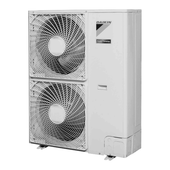
Summary of Contents for Daikin RZQ100KV4A
- Page 1 Si281316 REMOVAL PROCEDURE S E R V I C E M A N U A L 4/5/6 HP Class Outdoor Unit Inverter Pair Type...
- Page 2 Service Manual Removal Procedure Outdoor Unit Applicable Models Heat Pump RZQ100KV4A RZQ125KV4A RZQ150KV4A RZQ160KV4A...
-
Page 3: Table Of Contents
Si281316 Table of Contents 1. Procedure to Remove Outside Panels............2 2. Procedure to Remove Propeller Fan and Fan Motor ......3 3. Procedure to Remove Switch Box ............4 4. Procedure to Remove PCB..............5 5. Procedure to Remove Pressure Sensor, Electronic Expansion Valve, and Others ....................6 6. -
Page 4: Procedure To Remove Outside Panels
Procedure to Remove Outside Panels Si281316 1. Procedure to Remove Outside Panels Procedure Warning Be sure to wait for 10 minutes or more after turning off all power supplies before disassembling work. Procedure Points Step For the suction grille, pull the lower parts (in 7 places) frontward, disengage the hooks at the top of the grille with... -
Page 5: Procedure To Remove Propeller Fan And Fan Motor
Si281316 Procedure to Remove Propeller Fan and Fan Motor 2. Procedure to Remove Propeller Fan and Fan Motor Procedure Warning Be sure to wait for 10 minutes or more after turning off all power supplies before disassembling work. Procedure Points Step Remove the front panel (2) accordance with the... -
Page 6: Procedure To Remove Switch Box
Procedure to Remove Switch Box Si281316 3. Procedure to Remove Switch Box Procedure Warning Be sure to wait for 10 minutes or more after turning off all power supplies before disassembling work. Procedure Points Step Remove the front panel (2) accordance with the If the top panel cannot be Procedure to remove removed... -
Page 7: Procedure To Remove Pcb
Si281316 Procedure to Remove PCB 4. Procedure to Remove PCB Procedure Warning Be sure to wait for 10 minutes or more after turning off all power supplies before disassembling work. Procedure Points Step Remove the top panel and the front panel (2) Hooks accordance with the Procedure to remove... -
Page 8: Procedure To Remove Pressure Sensor, Electronic Expansion Valve, And Others
Procedure to Remove Pressure Sensor, Electronic Expansion Valve, and Others Si281316 5. Procedure to Remove Pressure Sensor, Electronic Expansion Valve, and Others Procedure Warning Be sure to wait for 10 minutes or more after turning off all power supplies before disassembling work. Step Procedure Points... -
Page 9: Procedure To Remove Thermistor
Si281316 Procedure to Remove Thermistor 6. Procedure to Remove Thermistor Procedure Warning Be sure to wait for 10 minutes or more after turning off all power supplies before disassembling work. Procedure Points Step Remove the top panel and the front panel (2) and side panel accordance with the Thermistor... -
Page 10: Procedure To Remove Four Way Valve
Procedure to Remove Four Way Valve Si281316 7. Procedure to Remove Four Way Valve Procedure Warning Be sure to wait for 10 minutes or more after turning off all power supplies before disassembling work. Procedure Points Step Recover the refrigerant. Be sure to remove the four According to the way valve only after the... -
Page 11: Procedure To Remove Compressor
Si281316 Procedure to Remove Compressor 8. Procedure to Remove Compressor Procedure Warning Be sure to wait for 10 minutes or more after turning off all power supplies before disassembling work. Procedure Points Step Recover the refrigerant. Be sure to remove the (Refer to point column.) compressor only after the Remove the front panel... - Page 12 Revision History Month / Year Version Revised contents 01/2013 Si281316 First edition...
- Page 13 Improper installation can result in water or refrigerant leakage, electrical shock, fire or explosion. Use only those parts and accessories supplied or specified by Daikin. Ask a qualified installer or contractor to install those parts and accessories. Use of unauthorised parts and accessories or improper installation of parts and accessories can result in water or refrigerant leakage, electrical shock, fire or explosion.


