
Related Manuals for MSI MS-6104


Summary of Contents for MSI MS-6104
- Page 1 Version 1.0 PENTIUM is a trademark of the Intel Corporation. PS/2 is a trademark of the IBM Corporation.
- Page 2 Mainboard Name: MS-6104 Manual Rev: 1.0 BIOS Version: W48X Release Date: June, 1996 FCC-B Radio Frequency Interference Statement This equipment has been tested and found to comply with the limits for a class B digital device, pursuant to part 15 of the FCC rules. These limits are designed to provide reasonable protection against harmful interference when the equipment is operated in a commercial environment.
- Page 3 Edition June 1996 Copyright Notice This manual is copyrighted. No guarantee is given as to the correctness of its contents. We reserve the right to make changes without notification. Trademarks All trademarks used in this manual are the property of their respective owners.
-
Page 4: Table Of Contents
Table of Contents Chapter 1: Introduction System Board Specifications ---------------------------------------- System Board Layout ------------------------------------------------ Chapter 2: Hardware Installation System Clock Selection: JC1--------------------- ------------------ Flash ROM Selection: JP3------------------------------------------- Power Saving Switch Connector: JG1----------------------------- CMOS RAM Clear: JP7---------------------------------------------- System Memory Installation: SIMM4 -SIMM1 ------------------- DRAM Installation---------------------------------------------------- CPU Installation &... - Page 5 Floppy Disk Connector : Floppy ------------------------------------ 2-12 Hard Disk Connector: IDE1 , IDE2----------------------------- 2-12 IrDA Infrared Module Connector: IRCON--------------------- 2-14 USB Connector : USB (USB1,USB2) --------------------------- 2-15 Chapter 3: AWARD BIOS SETUP (Version 4.51) Entering Setup------------------------------------------------------- Getting Help--------------------------------------------------------- The Main Menu----------------------------------------------------- Standard CMOS Setup ------------------------------------------- BIOS Features Setup ---------------------------------------------- Chipset Features Setup --------------------------------------------...
-
Page 6: Chapter 1: Introduction
CHAPTER 1 INTRODUCTION Chapter 1 INTRODUCTION The PCI P6 NA2 PCI/ISA system board is an ATX high-performance personal computer system board based on the Pentiumä Pro microprocessor. System Board Specifications Power Selection: · ATX or PS/2 Power Selection Hardware Installation: ·... - Page 7 CHAPTER 1 INTRODUCTION Chip Set: · The system board utilizes the Intel Pentium Pro Chipset which includes SB82441FX (PMC) PCI bridge and memory controller, and SB82442FX(DBX) Data Bus Accelerator and SB82371(P11X3) PCI to ISA Bridge. Multi-I/O: · The system board has a built in Plug and Play Winbond W83877 and Multi-I/O chipsets to support 2 high-speed serial ports, one parallel port with ECP and EPP capabilities, and one floppy drive.
- Page 8 CHAPTER 1 INTRODUCTION · Supports symmetric or asymmetric DRAM memory, 70ns or faster. · Provides ECC (Error Check Function) Function. Slots: · Four 32-bit PCI Bus slots and four 16-bit ISA bus slots. One shared slot that can be used as ISA or PCI. On-Board I/O: ·...
-
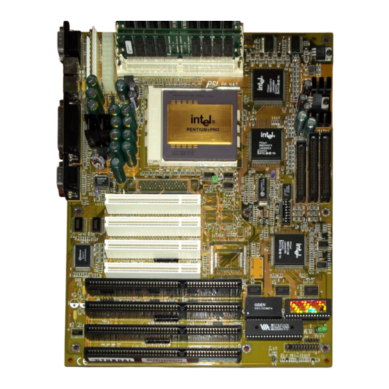
Page 9: 1.2 System Board Layout
CHAPTER 1 INTRODUCTION 1.2 System Board Layout Figure 1-1... -
Page 10: Chapter 2: Hardware Installation
CHAPTER 2 HARDWARE INSTALLATION Chapter 2 HARDWARE INSTALLATION It is important to set jumpers correctly. Improper jumper setting will cause system instability, destruction of components, and/or system hang-up. Step 1: Set the CPU BUS CLOCK and Core Frequency Ratio (see “JC1 Jumper” section) JC1 is used for CPU BUS CLOCK and bus to core frequency ratio. - Page 11 Hard Disk Connector 2-11 JFAN CPU Fan Connector 2-12 IRCON Infrared Module 2-12 CPU Frequency Selection: JC1 The CPU BUS CLOCK of the MS-6104 supports two frequencies: 60MHz (default) and 66MHz. Refer to the following figure for jumper location and settings.
-
Page 12: Flash Rom Selection: Jp3
CHAPTER 2 HARDWARE INSTALLATION JC1 SETTINGS Flash ROM Selection: JP3 Jumper JP3 sets the mainboard to be used with either +12V or +5V Flash ROM. -
Page 13: Power Saving Switch Connector: Jg1
CHAPTER 2 HARDWARE INSTALLATION Power Saving Switch: JG1 Attaching a power saving switch to this connector will allow the system into sleep mode whenever this switch is pressed. CMOS RAM Clear: JP1 The system board configuration is stored in CMOS RAM. If you need to clear the system board configuration do the following: 1. -
Page 14: System Memory Installation: Simm4 -Simm1
CHAPTER 2 HARDWARE INSTALLATION Note: Some CMOS RAMs require a different procedure: 1. Short jumper JP1. 2. Turn on system 3. Turn off the system 4. Remove JP1 jumper. 5. Turn on power again. 6. Reset BIOS. System Memory Installation: SIMM1-SIMM4 The system board provides four 72-pin SIMM sockets which are numbered from SIMM1 to SIMM4. -
Page 15: Dram Installation
CHAPTER 2 HARDWARE INSTALLATION 2. DRAM modules can be populated in any order (i.e. SIMM1/2 does not have to be populated before SIMM3/4 are used.) 3. DRAM module pairs need to be populated with the same densities...single or double. For example, SIMM1/2 sockets must be populated with identical densities. - Page 16 CHAPTER 2 HARDWARE INSTALLATION 1. Check to see which side of the plastic safety tab is on the slot before installing. 2. Line up the notch of the module against the slot. 3. Press the module firmly into place at a 45 degree angle. 4.
-
Page 17: Case Block Connector: Jfp
CHAPTER 2 HARDWARE INSTALLATION Case Block Connector : JFP The Turbo LED, Hardware Reset, Key lock, Power LED, Power Saving LED, Speaker,and HDD LED all connect to the JFP connector block as below. -
Page 18: Power Supply Connector
CHAPTER 2 HARDWARE INSTALLATION Note : The hardware Turbo switch is not functional. But the Turbo LED can be controled by software Turbo/Deturbo. Power Supply Connector The power supply connector is a twelve-pin male connector (J1) or a 2X10-pin ATX connector (J3). Dual connectors from the power supply can fit in only one direction. - Page 19 CHAPTER 2 HARDWARE INSTALLATION connector with the two black wires at the center as shown in the diagram below. 12-pin Connector Pin Description Description Description Power Good Ground +5V DC Ground +12V DC -5V DC -12V DC +5V DC Ground +5V DC 2 - 10...
-
Page 20: Keyboard Connector: Ps/2-Kb Or Jms1
CHAPTER 2 HARDWARE INSTALLATION Ground +5V DC 2X10-Pin Connector Pin Description Description Description 3.3V 3.3V 3.3V -12V GROUND GROUND PS-ON GROUND GROUND GROUND GROUND GROUND PW-OK 5VSV Keyboard Connector: PS/2-KB, or JMS1 Choose either PS/2-KB or JMS1 as a keyboard connector. The system board provides a standard five-pin female DIN connector for attaching a keyboard. -
Page 21: Mouse Connector: Jms Or Ps/2 Style Mouse
CHAPTER 2 HARDWARE INSTALLATION Mouse Connector: JMS or PS/2 Style Mouse Choose either PS/2 or JMS as a mouse connector. Serial Port Connectors: COM1 & COM2 The system board has two 9-pin male serial port connectors, COM1 and COM2. The two ports are 16550 high speed communication ports that send/receive 16 byte FIFOs. -
Page 22: Floppy Disk Connector: Floppy
CHAPTER 2 HARDWARE INSTALLATION Floppy Disk Connector: Floppy The system board also provides a standard floppy disk connector, FDD, that supports 360K, 720K, 1.2M, or 1.44M floppy disk types. You can attach a floppy disk cable directly to this connector. Hard Disk Connector: IDE1, IDE2 2 - 13... - Page 23 CHAPTER 2 HARDWARE INSTALLATION The system board has a 32-bit Enhanced PCI IDE Controller that provides for two HDD connectors, IDE1 (primary) and IDE2 (secondary). You can connect up to four hard disk drives or devices to IDE1 and IDE2. IDE1 (Pimary IDE Connector) If you only use one hard disk you must connect to IDE1.
-
Page 24: Irda Infrared Module Connector: Ircon
CHAPTER 2 HARDWARE INSTALLATION IrDA Infrared Module Connector: IRCON The system board provides a 5-pin infrared connector-JP4 as an optional module for wireless transmittng and receiving. Infrared ( IrDA/Consumer IR) Connector Serial Port 2 can be configured to support an IrDA module via a 5-pin header connector. -
Page 25: Usb Connector : Usb (Usb1,Usb2)
CHAPTER 2 HARDWARE INSTALLATION Remote On/Off: J10 The 2-pin connector must utilize a toggle switch (one push on/second push off). To use this function an ATX or PS/2 with a stand by +5V cable switch power is needed. Remote ON/OFF and Soft Power Support When connected to a momentary SPST switch, this 2-pin header is used to power up the system. - Page 26 CHAPTER 2 HARDWARE INSTALLATION SCSI Hard Disk Connector: J4 & J6 (optional) J4 is a 68-pin 16-bit SCSI Hard Disk Connector. J6 is a 50-pin 8- bit SCSI Hard Disk Connector. The SCSI controller interupt signal is shared with the PCI 4 slot. If you wish to install a PCI card in the PC1 4 slot, you must install the SCSI driver before installing any other drivers.
-
Page 27: Chapter 3: Award Bios Setup (Version 4.51)
Chapter 3 AWARD BIOS USER’S GUIDE Chapter 3 AWARD BIOS SETUP (Version 4.51) Award's BIOS ROM has a built-in Setup program that allows users to modify the basic system configuration. This type of information is stored in battery-backed RAM (CMOS RAM) so that it retains the Setup information when the power is turned off. -
Page 28: Getting Help
Chapter 3 AWARD BIOS USER’S GUIDE Getting Help Main Menu The on-line description of the highlighted setup function is displayed at the bottom of the screen. Status Page Setup Menu/Option Page Setup Menu Press F1 to pop up a small help window that describes the appropriate keys to use and the possible selections for the highlighted item. -
Page 29: The Main Menu
Chapter 3 AWARD BIOS USER’S GUIDE The Main Menu Once you enter Award BIOS CMOS Setup Utility, the Main Menu (Figure 1) will appear on the screen. The Main Menu allows you to select from ten setup functions and two exit choices. Use arrow keys to select among the items and press <Enter>... - Page 30 Chapter 3 AWARD BIOS USER’S GUIDE Standard CMOS setup This setup page includes all the items in a standard compatible BIOS. BIOS features setup This setup page includes all the items of Award special enhanced features. Chipset features setup This setup page includes all the items of chipset special features. Power Management setup This category determines how much power consumption for system after selecting below items.
- Page 31 Chapter 3 AWARD BIOS USER’S GUIDE Supervisor Password/User Password Change set or disable password. This function allows the user access to the system and setup or just setup. Load setup defaults Chipset defaults indicates the values required by the system for the maximum performance.
-
Page 32: Standard Cmos Setup
Chapter 3 AWARD BIOS USER’S GUIDE Standard CMOS Setup The items in Standard CMOS Setup Menu are divided into 10 categories. Each category includes no, one or more than one setup items. Use the arrow keys to highlight the item and then use the <PgUp>... - Page 33 Chapter 3 AWARD BIOS USER’S GUIDE Date The date format is <day><month> <date> <year>. Day of the week, from Sun to Sat, determd. by BIOS, read only month The month Jan through Dec date The date from 1 to 31 can be keyed by numeric function keys year The year, depends on the year of the BIOS Time...
- Page 34 Chapter 3 AWARD BIOS USER’S GUIDE If the controller of HDD interface is ESDI, the selection shall be “Type 1”. If the controller of HDD interface is SCSI, the selection shall be “None”. If the controller of HDD interface is CD-ROM, the selection shall be “None”.
-
Page 35: Bios Features Setup
Chapter 3 AWARD BIOS USER’S GUIDE BIOS Features Setup ROM PCI/ISA BIOS (2A69HM49) BIOS FEATURES SETUP AWARD SOFTWARE, INC. Virus Warning : Disabled Video BIOS Shadow :Enabled CPU Internal Cache : Enabled C8000-CBFFF Shadow :Disabled External Cache : Enabled CC000-CFFFF Shadow :Disabled Quick power on Self Test : Disabled... - Page 36 Chapter 3 AWARD BIOS USER’S GUIDE !WARNING! Disk boot Sector is to be modified Type “Y” to accept write or “N” to abort write Award Software, Inc. Disabled No warning message to appear when anything attempts (default) to access the boot sector or hard disk partition table. Enabled Activates automatically when the system boots up causing a warning message to appear when anything...
- Page 37 Chapter 3 AWARD BIOS USER’S GUIDE Quick Power On Self Test This category speeds up Power On Self Test (POST) after you power on the computer. If it is set to Enable, BIOS will shorten or skip some check items during POST. Enabled Enable quick POST Disabled (default)
- Page 38 Chapter 3 AWARD BIOS USER’S GUIDE Boot Up Floppy Seek During POST, BIOS will determine if the floppy disk drive installed is 40 or 80 tracks. 360K type is 40 tracks while 720K, 1.2M and 1.44M are all 80 tracks. Enabled BIOS searches for floppy disk drive to determine if (default)
- Page 39 Chapter 3 AWARD BIOS USER’S GUIDE Gate A20 Option Normal The A20 signal is controlled by keyboard controller or chipset hardware. Fast Default : Fast. The A20 signal is controlled by (default) Port 92 or chipset specific method. Typematic Rate Setting This determines the typematic rate Enabled Enable typematic rate and typematic delay...
- Page 40 Chapter 3 AWARD BIOS USER’S GUIDE Security Option This category allows you to limit access to the system and Setup, or just to Setup. System The system will not boot and access to Setup will be denied if the correct password is not entered at the prompt.
- Page 41 Chapter 3 AWARD BIOS USER’S GUIDE In this case, the PCI VGA controller should not respond to the Write, it should only snoop the data and permit the access to be forwarded to the ISA bus. The non-VGA ISA graphic controller can then snoop the data on the ISA bus.
-
Page 42: Chipset Features Setup
Chapter 3 AWARD BIOS USER’S GUIDE Chipset Features Setup The Chipset Features Setup option is used to change the values of the chipset registers. These registers control most of the system options in the computer. Note: Change these settings only if you are familiar with the chipset. Choose the “CHIPSET FEATURES SETUP”... - Page 43 Chapter 3 AWARD BIOS USER’S GUIDE Auto Configuration Choosing Enabled (default) will automatically configure chipset features using default settings. Choose Disable to customize setup. DRAM Speed Selection Sets the DRAM speed at 70ns (default) or 60ns. RAS# to Cas# Delay Choosing Enabled will insert one clock delay between the RAS# and CAS#.
- Page 44 Chapter 3 AWARD BIOS USER’S GUIDE Note: B stands for BEDO (Burst Extended Data Output) DRAM. E stands for EDO (Extended Data Output) DRAM F stands for FP (Fast Page) DRAM Example: If the user chooses DRAM Read Burst (B/E/F): x2/3/4 it signifies that: 2 is used for setting BEDO 3 is used for setting EDO...
- Page 45 Chapter 3 AWARD BIOS USER’S GUIDE ECC Checking Generation The system chipset supports Error Code Correct (ECC) checking and generation. To use this setting the system needs to be used with a parity bit DRAM module. Disabled is the default setting. Fast DRAM Refresh Choosing Disabled (default) will select the normal mode where the refresh rate is every 15ns.
- Page 46 Chapter 3 AWARD BIOS USER’S GUIDE PCI To DRAM Pipeline Choosing Disabled will restrict pipelining of PCI DRAM write cycles. Enabled is the default. CPU To PCI Write Post Choosing Enabled will enable CPU to PCI posting. CPU To PCI IDE Posting Choosing Disabled will allow the I/O Write port and the 1F0h and 170h to be treated as normal I/O Write Transactions.
- Page 47 Chapter 3 AWARD BIOS USER’S GUIDE 8-bit I/O recovery time: 1/2/3/4/5/6/7/NA 16-bit I/O recovery time: 1/2/3/NA Choose the recovery time for 8-bit and 16-bit I/O cycles respectively. Note: NA is not available and so the recovery time of 3.5 SYSCLK is inserted.
-
Page 48: Power Management Setup
Chapter 3 AWARD BIOS USER’S GUIDE Power Management Setup The Power management setup will appear on your screen like this: ROM PCI/ISA BIOS (2A69HM49) POWER MANAGEMENT SETUP AWARD SOFTWARE, INC. Power Management : Disable **Power Down & Resume Events* PM Control by APM : Yes IRQ3 (COM 2) : OFF... - Page 49 Chapter 3 AWARD BIOS USER’S GUIDE Item Options Descriptions Power 1. Disable Global Power Management (Min. Saving) will be disabled. Management 2. User Define Users can configure their (Max. Saving) own power management. 3. Min Saving Pre-defined timer values are used such that all timers are in their MAX value.
- Page 50 Chapter 3 AWARD BIOS USER’S GUIDE Item Options Descriptions Video 3. DPMS This function is enabled for only the VGA card supporting DPMS. Method (cont.) Note: Green monitors detect the V/H SYNC signals to turn off its electron gun. Doze 1.
- Page 51 Chapter 3 AWARD BIOS USER’S GUIDE Item Options Description Standby 1. Disable System will never enter STANDBY mode. Mode 2. 1 Min Defines the continuous idle time before the 2 Min system entering STANDBY mode. 4 Min 6 Min if any item defined in The Options of 8 Min “Power Down and Resume events”...
- Page 52 Chapter 3 AWARD BIOS USER’S GUIDE Suspend Mode 1. Disable System will never enter SUSPEND mode. 2. 1 Min Defines the continuous idle 2 Min time before the system 4 Min entering SUSPEND mode. 6 Min 8 Min if any item defined in the 10 Min Options of “Power Down &...
- Page 53 Chapter 3 AWARD BIOS USER’S GUIDE Item Options Descriptions 1. Disable HDD’s motor will not shut off. Power Down 2. 1 Min Defines the continous HDD 2 Min idle time before the HDD 3 Min enters the power saving 4 Min mode (motor off).
- Page 54 Chapter 3 AWARD BIOS USER’S GUIDE Power Down and Resume Events IRQ3 (COM 2) :ON/OFF IRQ4 (COM 1) :ON/OFF IRQ5 (LPT 2) :ON/OFF IRQ6 (Floppy Disk) :ON/OFF IRQ7 (LPT 1) :ON/OFF IRQ9 (IRQ2 Redir) :ON/OFF IRQ10 (Reserved) :ON/OFF IRQ11 (Reserved) :ON/OFF IRQ12 (PS/2Mouse) :ON/OFF...
-
Page 55: Pnp/Pci Configuration Setup
Chapter 3 AWARD BIOS USER’S GUIDE PNP/PCI Configuration Setup You can manually configure the PCI Device’s IRQ. The following pages tell you the options of each item & describe the meanings of each options. ROM PCI/ISA BIOS (2A69HM49) PNP/PCI CONFIGURATION SETUP AWARD SOFTWARE, INC. - Page 56 Chapter 3 AWARD BIOS USER’S GUIDE Resources Controlled By By Choosing “Auto” the system BIOS will detect the system resource and automatically assign the relative IRQ and DMA Channel for each peripheral. Note: There are limitations to this function. For example when choosing “Auto”...
-
Page 57: Load Bios/Setup Defaults
Chapter 3 AWARD BIOS USER’S GUIDE IRQ-14 assigned to : PCI/ISA PnP IRQ-15 assigned to : PCI/ISA PnP DMA-0 assigned to : PCI/ISA PnP DMA-1 assigned to : PCI/ISA PnP DMA-3 assigned to : PCI/ISA PnP DMA-5 assigned to : PCI/ISA PnP DMA-6 assigned to : PCI/ISA PnP DMA-7... - Page 58 Chapter 3 AWARD BIOS USER’S GUIDE This Main Menu item loads the default system values. If the CMOS is corrupted the defaults are loaded automatically. Choose this item and the following message appears: " Load Setup Defaults (Y / N) ? N " To use the Setup defaults, change the prompt to "Y"...
-
Page 59: Integrated Peripherals
Chapter 3 AWARD BIOS USER’S GUIDE Integrated Peripherals ROM PCI/ISA BIOS (2A69HM49) INTEGRATED PERIPHERALS AWARD SOFTWARE, INC. IDE HDD Block Mode : Enabled USB Controller : Disabled IDE Primary Master PIO : Auto IDE Primary Slave PIO : Auto IDE Secondary Master PIO : Auto IDE Secondary Slave PIO : Auto... - Page 60 Chapter 3 AWARD BIOS USER’S GUIDE IDE Primary Master PIO: Auto/Mode0/Mode1-4 IDE Primary Slave PIO: Auto/Mode0/Mode1-4 IDE Secondary Master PIO: Auto/Mode0/Mode1-4 IDE Secondary Slave PIO: Auto/Mode0/Mode1-4 For these 4 IDE option choose “Auto” to have the system BIOS auto detect the IDE HDD operation mode for PIO access. Note: Some IDE HDD can not operate at the responding HDD’s mode.
- Page 61 Chapter 3 AWARD BIOS USER’S GUIDE Secondary PCI IDE: Enabled/Disabled The system provides for a On-Board On-Chipset PCI IDE controller that supports Dual Channel IDE (Primary and Secondary). A maximum of 4 IDE devices can be supported. If the user to install the Off-Board PCI IDE controller (i.e.
- Page 62 Chapter 3 AWARD BIOS USER’S GUIDE The system has an On-board Super I/O chipset with 2 serial ports. The On-board serial ports can be selected as: Disabled 3F8/IRQ4 COMM1 uses IRQ4 2F8/IRQ3 COMM2 uses IRQ3 3E8/IRQ4 COMM3 uses IRQ4 2E8/IRQ3 COMM4 uses IRQ3 Note: Because the ISA Bus Interrupt accepts low to high edge trigger, the interrupt request line can not be shared by multiple sources.
- Page 63 Chapter 3 AWARD BIOS USER’S GUIDE RxD, TxD Active: Hi-Hi/Hi-Lo/Lo-Hi/Lo-L0 The user can choose between the preceding RxD (Receive Data), TxD (Transmit Data) activity levels. Onboard Parallel Port: Disabled/(3BCH/IRQ7)/ (278H/IRQ5)/(378H/IRQ7) There is a built-in parallel port on the on-board Super I/O chipset that provides Standard, ECP, and EPP features.
- Page 64 Chapter 3 AWARD BIOS USER’S GUIDE ECP and EPP modes simultaneously. The ECP mode has to use the DMA channel so choose the onboard parallel port with the ECP feature. After selecting it the following message will appear: “ECP Mode Use DMA” At this time the user can choose between DMA channels 3 or 1.
-
Page 65: Supervisor/User Password Setting
Chapter 3 AWARD BIOS USER’S GUIDE Supervisor/User Password Setting This Main Menu item lets you configure the system so that a password is required each time the system boots or an attempt is made to enter the Setup program. Supervisor Password allows you to change all CMOS settings but the User Password setting doesn't have this function. - Page 66 Chapter 3 AWARD BIOS USER’S GUIDE IDD HDD Auto Detection You can use this utility to automatically detect the characteristics of most hard drives. When you enter this utility, the screen asks you to select a specific hard disk for Primary Master. If you accept a hard disk detected by the BIOS, you can enter "Y"...