Advertisement
Quick Links
RadioCom
Telex Communications, Inc.
INSTRUCTION SHEET
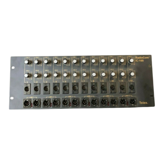
General Description
The IC-100 allows the assignment of any two of six
input lines to any one of twelve two channel outputs.
In addition, the six input lines are available as a loop
through output. All input are protected against
transients and power crosses.
Specifications
Bridging Impedance...................44k Each Channel
Supply Current ........................20ma Each Channel
Peak Pulse Capability..................................1500W
Fuse Rating ....................................1.5A Fast Blow
Overvoltage Protection < 1.5A Indefinite Duration
Size (Approximate).................H: 7.00" (177.8mm)
Weight (Approximate)..................10 lbs. (4.54 kg)
Patents ........................................................Pending
IC-100 Product Features
• Input and output connections are compatible with
BTR-1 Wireless Intercom.
• Non-shorting rotary switches allow reconfiguration
without channel cross-connection.
• An active power monitor indicates the presence of
power on all input lines with minimal loading.
• D sub to XLR breakout on rear panel.
TM
W: 19.00" (482.6mm)
D: 5.00" (127mm)
IC-100
CAT. NO. 301971000
INTERCOM SOURCE ASSIGN PANEL
Inputs
There are two ways to connect input lines to the
IC-100:
1. Feed the lines into the 15 pin D sub connector on
the rear panel marked I/C IN. The pin assignments
are shown in Table 1.
2. Connect a patch cable between I/C IN and
EXTERNAL LINES OUTPUT on the rear panel
and feed the lines into the six XLR connectors
marked EXTERNAL LINES INPUT.
XLR Equivalent
LINE 1 PIN 2
LINE 1 PIN 3
LINE 2 PIN 2
LINE 2 PIN 3
LINE 3 PIN 2
LINE 3 PIN 3
LINE 4 PIN 2
LINE 4 PIN 3
LINE 5 PIN 2
LINE 5 PIN 3
LINE 6 PIN 2
LINE 6 PIN 3
GND
GND
GND
Table 1 - Inputs
PN 804203
D Conn Pin Number
1
9
2
10
3
11
4
12
5
13
6
14
7
8
15
Advertisement

Related Manuals for Telex RadioCom IC-100


Summary of Contents for Telex RadioCom IC-100
- Page 1 RadioCom IC-100 CAT. NO. 301971000 Telex Communications, Inc. INTERCOM SOURCE ASSIGN PANEL PN 804203 INSTRUCTION SHEET General Description Inputs The IC-100 allows the assignment of any two of six There are two ways to connect input lines to the input lines to any one of twelve two channel outputs.
- Page 2 LINE 3 LINE 2 LINE 1 LINE 5 IC-100 P/N: 879944 SN: XXXX Telex Communication, Inc. 5 or 11 8601 East Cornhusker Highway, Lincoln, NE 68507 Made in U.S.A. 804070 CHANNEL 2 PIN 2 CHANNEL 2 PIN 3 Rear View - IC-100...