Table of Contents
Advertisement
Available languages
Available languages
Quick Links
OPERATOR'S MANUAL
MANUEL D'UTILISATION
MANUAL DEL OPERADOR
SDS+ HAMMER DRILL
PERCEUSE À PERCUSSION
DE SDS+
TALADRO DE PERCUSIÓN
DE SDS+
SDS65
INCLUDES: Hammer Drill, Auxiliary Handle
Assembly with Depth Stop Rod, Operator's
Manual
****************
TABLE OF CONTENTS
Warnings .........................................2-3
Hammer Drill Safety Warnings ........... 3
Symbols ..............................................4
Electrical .............................................5
Features ..............................................6
Assembly .........................................6-7
Operation .........................................7-9
Maintenance ..................................... 10
Illustrations ..................................11-12
Parts Ordering / Service ..... Back Page
WARNING:
To reduce the
risk of injury, the user must read and
understand the operator's manual
before using this product.
SAVE THIS MANUAL FOR
FUTURE REFERENCE
INCLUT : Perceuse à percussion, poignée
auxiliaire et tige de butée de profondeur,
manuel d'utilisation
****************
TABLE DES MATIÈRES
aux outils électriques ......................2-3
relatifs perceuse à percussion ........... 3
Symboles ............................................4
Caractéristiques électriques ............... 5
Caractéristiques ................................. 6
Assemblage .....................................6-7
Utilisation .........................................7-9
Entretien ...........................................10
Illustrations ..................................11-12
Commande de pièces/
réparation ..........................Page arrière
AVERTISSEMENT :
réduire les risques de blessures,
l'utilisateur doit lire et veiller à bien
comprendre le manuel d'utilisation
avant d'employer ce produit.
CONSERVER CE MANUEL
POUR FUTURE RÉFÉRENCE
INCLUYE: Taladro de percusión, mango
auxiliar con barra limitadora de profundidad,
manual del operador
****************
ÍNDICE DE CONTENIDO
Advertencias de seguridad
para herramientas eléctricas ...........2-3
Advertencias de seguridad
taladro de percusión .......................... 3
Símbolos ............................................4
Aspectos eléctricos ............................ 5
Características ................................... 6
Armado ............................................6-7
Funcionamiento .............................7-10
Mantenimiento .................................. 10
Ilustraciones ................................11-12
Pedidos de piezas /
Servicio ......................... Pág. posterior
ADVERTENCIA:
Pour
el riesgo de lesiones, el usuario debe
leer y comprender el manual del
operador antes de usar este producto.
GUARDE ESTE MANUAL
PARA FUTURAS CONSULTAS
Para reducir
Advertisement
Table of Contents

Related Manuals for Ryobi SDS65


Summary of Contents for Ryobi SDS65
-
Page 1: Table Of Contents
SDS+ HAMMER DRILL PERCEUSE À PERCUSSION DE SDS+ TALADRO DE PERCUSIÓN DE SDS+ SDS65 INCLUDES: Hammer Drill, Auxiliary Handle INCLUT : Perceuse à percussion, poignée INCLUYE: Taladro de percusión, mango auxiliaire et tige de butée de profondeur, Assembly with Depth Stop Rod, Operator’s auxiliar con barra limitadora de profundidad, manuel d’utilisation... -
Page 2: General Power Tool Safety Warnings
GENERAL POWER TOOL SAFETY WARNINGS Prevent unintentional starting. Ensure the switch is in the off-position before connecting to power source WARNING and/or battery pack, picking up or carrying the tool. Read all safety warnings and all instructions. Failure to Carrying power tools with your finger on the switch or follow the warnings and instructions may result in electric energising power tools that have the switch on invites... -
Page 3: Hammer Drill Safety Warnings
GENERAL POWER TOOL SAFETY WARNINGS Use the power tool, accessories and tool bits etc. When servicing a power tool, use only identical in accordance with these instructions, taking into replacement parts. Follow instructions in the Main- account the working conditions and the work to be tenance section of this manual. -
Page 4: Symbols
SYMBOLS The following signal words and meanings are intended to explain the levels of risk associated with this product. SYMBOL SIGNAL MEANING Indicates a hazardous situation, which, if not avoided, will result in death or DANGER: serious injury. Indicates a hazardous situation, which, if not avoided, could result in death or WARNING: serious injury. -
Page 5: Electrical
ELECTRICAL DOUBLE INSULATION EXTENSION CORDS Double insulation is a concept in safety in electric pow- When using a power tool at a considerable distance from er tools, which eliminates the need for the usual three- a power source, be sure to use an extension cord that has wire grounded power cord. -
Page 6: Features
FEATURES PRODUCT SPECIFICATIONS Chuck Capacity ............SDS+ Switch ......Variable Speed Reversible (VSR) Drilling Capacity: Blows Per Minute ..........0-4,200 BPM Concrete ..............1 in. No Load Speed ........0-1,000 r/min. (RPM) Metal ..............1/2 in. Input .......120 V, AC only, 60 Hz, 6.5 Amps ASSEMBLY UNPACKING WARNING:... -
Page 7: Operation
OPERATION VARIABLE SPEED WARNING: The variable speed dial delivers higher speed by turning the Do not allow familiarity with products to make you care- variable speed dial clockwise. For slower speeds, turn the less. Remember that a careless fraction of a second is dial counterclockwise. - Page 8 OPERATION NOTE: When properly installed, the teeth on the depth stop NOTICE: rod should be aligned with the teeth indicator on the depth To prevent gear damage, always allow the chuck to stop clamp. come to a complete stop before changing the direction Adjust the depth stop rod so that the drill bit extends of rotation.
- Page 9 OPERATION Hold the drill firmly and place the bit at the point to be Metal and Steel Drilling drilled, or where the screw is to be driven. Select Rotational Drilling Mode. Use a light oil on the drill bit to keep it from overheating. WARNING: The oil will prolong the life of the bit and increase the Do not drive a screw where there is likely to be hidden...
-
Page 10: Maintenance
MAINTENANCE Electric tools used on fiberglass material, wallboard, WARNING: spackling compounds, or plaster are subject to acceler- ated wear and possible premature failure because the When servicing, use only identical replacement parts. fiberglass chips and grindings are highly abrasive to bear- Use of any other parts could create a hazard or cause ings, brushes, commutators, etc. -
Page 11: Règles De Sécurité Relatives Aux Outils Électriques
RÈGLES DE SÉCURITÉ RELATIVES AUX OUTILS ÉLECTRIQUES SÉCURITÉ PERSONNELLE AVERTISSEMENT Rester attentif, prêter attention au travail et faire preuve de bon sens lors de l’utilisation de tout outil électrique. Lire tous les avertissements et toutes les instructions. Ne pas utiliser cet outil en état de fatigue ou sous Ne pas suivre l’ensemble des avertissements et des l’influence de l’alcool, de drogues ou de médicaments. -
Page 12: Avertissements De Sécurité Relatifs Perceuse À Percussion
RÈGLES DE SÉCURITÉ RELATIVES AUX OUTILS ÉLECTRIQUES Ranger les outils motorisés hors de la portée des enfants Utiliser l’outil, les accessoires et embouts, etc. et ne laisser personne n’étant pas familiarisé avec l’outil conformément à ces instrutions pour les applications ou ces instructions utiliser l’outil. -
Page 13: Symboles
SYMBOLES Les termes de mise en garde suivants et leur signification ont pour but d’expliquer le degré de risques associé à l’utilisation de ce produit. SYMBOLE SIGNAL SIGNIFICATION Indique une situation dangereuse qui, si elle n’est pas évitée, aura pour conséquences DANGER : des blessures graves ou mortelles. -
Page 14: Caractéristiques Électriques
CARACTÉRISTIQUES ÉLECTRIQUES DOUBLE ISOLATION Pour le travail à l’extérieur, utiliser un cordon prolongateur spécialement conçu à cet effet. Ce type de cordon porte La double isolation est un dispositif de sécurité utilisé sur les l’inscription « W-A » ou « W » sur sa gaine. outils à... -
Page 15: Caractéristiques
CARACTÉRISTIQUES SPÉCIFICATIONS DU PRODUIT Capacité du mandrin ..........SDS+ Gâchette ......Vitesse variable réversible (VSR) Capacité de perçage : Golpes por minuto ..........0-4 200 CPM Béton ............25,4 mm (1 po) Vitesse à vide ........0 à 1 000 r/min (RPM) Métal ............13 mm (1/2 po) Alimentation.... -
Page 16: Utilisation
UTILISATION NOTE : L’utilisation de la perceuse à faible vitesse de façon AVERTISSEMENT : continue peut entraîner une surchauffe. Si la perceuse surchauffe, la refroidir en la laissant tourner à vide et à la Ne pas laisser la familiarité avec le produit faire oublier vitesse maximum. - Page 17 UTILISATION Ajuster la tige de butée de profondeur de façon à ce que le foret AVIS : dépasse de l’extrémité de la tigeà la profondeur de perçage Pour éviter des dommages aux engrenages, toujours laisser désirée. le mandrin parvenir à l’arrêt complet avant de changer de Lors du perçage de trous avec la tige de butée de profondeur sens de rotation.
- Page 18 UTILISATION Brancher la perceuse sur une prise secteur. Perçage du métal et acier Tenir la perceuse fermement et placer la pointe de l’embout Sélectionner le mode de perçage rotatif. sur le point à percer, ou à l’endroit ou la vis doit être ...
-
Page 19: Entretien
ENTRETIEN Les outils électriques utilisés sur la fibre de verre, le placoplâtre, AVERTISSEMENT : les mastics de bouchage ou le plâtre s’usent plus vite et sont susceptibles de défaillance prématurée, car les particules et Utiliser exclusivement des pièces identiques à celles les éclats de fibre de verre sont fortement abrasifs pour les d’origine pour les réparations. - Page 20 ADVERTENCIAS DE SEGURIDAD PARA HERRAMIENTAS ELÉCTRICAS SEGURIDAD PERSONAL ADVERTENCIA Permanezca alerta, preste atención a lo que esté haciendo y aplique el sentido común al utilizar herramientas eléctricas. Lea todas las advertencias de seguridad y las No utilice la herramienta eléctrica si está cansado o se instrucciones.
- Page 21 ADVERTENCIAS DE SEGURIDAD PARA HERRAMIENTAS ELÉCTRICAS ajuste, cambiarle accesorios o guardarla. Tales medidas Utilice la herramienta eléctrica, los accesorios y brocas, preventivas de seguridad reducen el riesgo de poner en marcha hojas y cuchillas de corte, ruedas de esmeril, etc. de accidentalmente la herramienta.
- Page 22 SÍMBOLOS Las siguientes palabras de señalización y sus significados tienen el objeto de explicar los niveles de riesgo relacionados con este producto. SÍMBOLO SEÑAL SIGNIFICADO Indica una situación peligrosa, la cual, si no se evita, causará la muerte o PELIGRO: lesiones serias.
- Page 23 ASPECTOS ELÉCTRICOS CORDONES DE EXTENSIÓN DOBLE AISLAMIENTO Al utilizar una herramienta eléctrica a una distancia considerable El doble aislamiento es una característica de seguridad de las de la fuente de voltaje, asegúrese de utilizar un cordón de herramientas eléctricas, la cual elimina la necesidad de usar extensión con la suficiente capacidad para soportar la corriente el típico cordón eléctrico de tres conductores con conexión a de consumo de la herramienta.
- Page 24 CARACTERÍSTICAS ESPECIFICACIONES DEL PRODUCTO Capacidad del portabrocas ........SDS+ Interruptor ....Velocidad variable e invertible (VSR) Capacidad de taladrar: Golpes por minuto ........0-4 200 GPM Concreto ..........25,4 mm (1 pulg.) Velocidad en vacío ......0-1 000 r/min (RPM) Metal ............13 mm (1/2 pulg.) Corriente de entrada .
- Page 25 FUNCIONAMIENTO VELOCIDAD VARIABLE ADVERTENCIA: El selector de velocidad variable permite la velocidad más alta girando el selector de velocidad variable derecha. Para las No permita que su familarización con este producto le vuelva velocidades más lentas, giran el selector izquierda. descuidado.
- Page 26 FUNCIONAMIENTO NOTA: Cuando se instala correctamente, los dientes de la AVISO: barra limitadora de profundidad deben estar alineados con el Para evitar dañar el engranaje, antes de cambiar el sentido indicador de dientes de la abrazadera de dicha barra. de rotación siempre permita que se detenga completamente Ajuste la barra limitadora de profundidad de manera que la el portabrocas.
- Page 27 FUNCIONAMIENTO Enchufe el taladro en el suministro de corriente. Al taladrar orificios de lado a lado, coloque un bloque de madera detrás de la pieza de trabajo para evitar producir Sostenga firmemente el taladro y coloque la broca en el orillas deshilachadas o astilladas en la parte posterior del punto donde va a taladrar, o en el punto donde el tornillo orificio.
- Page 28 MANTENIMIENTO Las herramientas eléctricas que se utilizan en materiales de ADVERTENCIA: fibra de vidrio, paneles de yeso para paredes, compuestos de resanar o yeso, están sujetas a desgaste acelerado y posible Al dar servicio a la unidad, utilice sólo piezas de repuesto fallo prematuro porque las partículas y limaduras de fibra de idénticas.
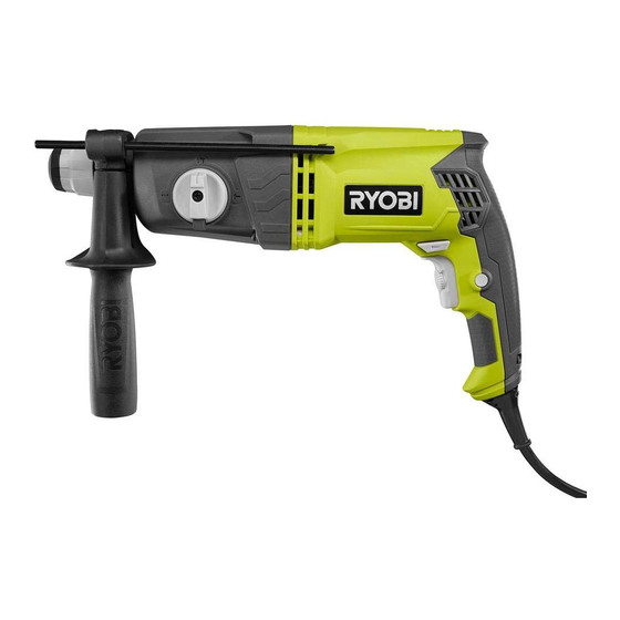
- Page 29 SDS65 A - Drilling/hammer mode selector (sélecteur E - Switch trigger (gachette, gatillo H - Variable speed dial (cadran à vitesse variable, de mode rotation / percussion, selector de interruptor) dial de velocidad variable) taladro/percusión) F - Direction of rotation selector (forward/ I - Power cord (cordon d’alimentation, cordón...
- Page 30 Fig. 4 Fig. 6 SDS Plus RIGHT / CORRECT / FORMA CORRECTA A - Pull clamp collar back (tirer le collier de serrage vers l’arrière, tire hacia atrás el collar de la mordaza) A - Rotational drilling mode (mode de perçage C - Chisel only mode (Mode de ciselage seulement, B - Insert or remove drill bit (insérer ou retirer rotatif, modo taladro rotacional)
- Page 31 NOTES / NOTAS...
- Page 32 RYOBI is a registered trademark of Ryobi Limited and is used pursuant to a license granted by Ryobi Limited. Pour faire une demande de réparations ou obtenir des pièces de rechange, trouver un Centre de réparations agréé...