Advertisement
Quick Links
®
BENDIX
360CC SINGLE CYLINDER COMPRESSOR FOR
INTERNATIONAL MAXXFORCE
DESCRIPTION
The function of the air compressor is to provide and
maintain air under pressure to operate devices in air brake
®
systems. The Bendix
cylinder compressor with a rated displacement of 15.8 cubic
feet per minute at 1250 RPM. The compressor consists
of an integral water-cooled cylinder head assembly and
water-cooled crankcase.
The cylinder head assembly is made up of an aluminum
cylinder head, an aluminum cooling plate, and a steel valve
plate assembly with two sealing gaskets. The cylinder head
contains air and water ports. The cooling plate, situated
between the head and valve plate, assists in cooling the
head assembly. The valve plate assembly, consisting of
brazed steel plates, has separate valve openings and
passages to allow air and coolant to fl ow in and out of the
compressor. See Figure 1 for an external view, and Figure
3 for an exploded view .
The compressor is equipped with a safety valve in the
cylinder head safety valve port, directly connected to the
discharge port. The safety valve protects the compressor
head in the event of excessively high discharge line
pressure, for example, in the event of blockage downstream
of the compressor. Excessive air pressure causes the
safety valve to unseat, releases air pressure and gives an
audible alert to the operator.
The compressor is cooled by air fl ow, as well as by engine
coolant. The engine coolant fi rst enters the crankcase
water jacket to cool the cylinder bore, then passes through
passages in the valve plate assembly, cooling plate, and
cylinder head and then out of a port at the top of the
compressor, back to the engine.
A nameplate is attached to a fl at cast face on the side of
the crankcase. It is stamped with information identifying
the compressor designation, customer piece number,
compressor assembly part number and serial number.
See Figure 2 .
™
360cc compressor is a single-
11 AND 13 BIG BORE ENGINES
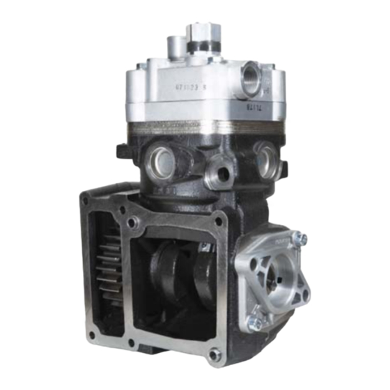
Coolant Exits at
Top of Head
(See Figure 7)
Cylinder
Head
Valve Plate
Assembly
Locating
Pins
FIGURE 1 - BENDIX
COMPRESSOR
A
C
FIGURE 2 - NAMEPLATES (TWO STYLES)
GENERAL INFORMATION
This Bendix
unloader" (DLU)-style compressor, meaning that the
compressor pumps continuously, unlike some compressor
designs which use an "unloader" mechanism in the
compressor head to switch from a pumping mode to a
non-pumping mode. Instead, the control of air delivery to
the vehicle's air system is managed by using a separate
discharge line unloader valve mounted in parallel with a
turbo cut-off style of air dryer (see Figure 6).
MAXXFORCE
®
360cc SINGLE CYLINDER
B
Bendix Part Number . . . . . . A
Customer Piece Number . . . . B
Compressor Serial Number . . C
®
360cc compressor is a "discharge line
™
is a trademark of International Engine Intellectual Property Company, LLC.
Safety
Valve
Cooling
Plate
Coolant
Enters Here
Crankcase
C
A
B
Advertisement

Related Manuals for BENDIX 360CC


Summary of Contents for BENDIX 360CC
- Page 1 Bendix Part Number ..A Customer Piece Number ..B The compressor is cooled by air fl ow, as well as by engine Compressor Serial Number .
- Page 2 Nameplate Drive Gear Crankshaft ® FIGURE 3 - BENDIX 360cc SINGLE CYLINDER COMPRESSOR (CUT-AWAY VIEW) The crankcase has an open side with a machined face Discharge Air Inlet and locating pins. This open face is bolted directly to the Valve...
- Page 3 ® Note: The Bendix 360cc compressor is a discharge line unloader-style unit. This means that the compressor Air Inlet Discharge functions in a continuous pumping mode regardless Port Valve Open whether the brake system requires air. It requires a Discharge downstream device (e.g.
- Page 4 fl ow. Minimum coolant line The Bendix ® 360cc Single Cylinder Compressors is size is 3/8" I.D. Check coolant lines for internal clogging only permitted to be naturally aspirated – use of engine from rust scale. If coolant lines appear suspicious, check turbocharger as an air source is not permitted.
- Page 5 In addition, SERVICE TESTS Bendix has developed the “Bendix Air System Inspection GENERAL Cup” or BASIC kit to help substantiate suspected excessive oil passing. The steps to be followed when using the BASIC The compressor operating and leakage tests listed below kit are presented in APPENDIX B, on page A-16.
- Page 6 Refer to the various maintenance manuals for individual component leakage tests and the MAINTENANCE KITS & SERVICE PARTS ® Bendix “Test and Checklist” published in the Bendix Brake System Handbook (BW5057) and on the back of ® BENDIX...
- Page 7 Refer to the Engine Manufacturers service ® 8. Use only genuine Bendix brand replacement parts, manual to address the associated engine drive parts. components and kits. Replacement hardware, tubing, 8.
- Page 8 Kit 3: Compressor Seal Kit (Minor) (K051352) End Cover O-Ring (Kit 2 & 3) Cover (Kit 2 & 3) Crankcase Crankcase O-ring (Kit 2) Valve Plate Assembly Cooling Plate Cylinder Head FIGURE 8 – BENDIX ® 60cc SINGLE CYLINDER COMPRESSOR EXPLODED VIEW...
- Page 9 6. Gently tap the cylinder head (15), cooling plate (14) and M8x1.25 valve plate assembly (13) with a soft mallet to break M10x1.5 the gasket seals. Then separate the cylinder head (15) Screws Screws from the cooling plate (14) and valve plate assembly (Smaller) (Larger) (13), and remove and discard the two head gaskets (4)
- Page 10 the compressor must be replaced. If large amounts of REAR END COVER carbon build-up are present on the two main surfaces, in 1. Install the o-ring (9) on the rear end cover. the two discharge valve holes or between the discharge 2.
- Page 11 ® 8. Install the washer (3) and safety valve (2) in the top BENDIX 360CC SINGLE CYLINDER port (discharge port) of the cylinder head (15), then COMPRESSOR SPECIFICATIONS tighten to a torque of 59 to 66 foot pounds (80-90 Nm).
- Page 12 Notes...
- Page 13 Appendix A Advanced Troubleshooting Guide for Air Brake Compressors The guide consists of an introduction to air brake charging system components, a table showing recommended vehicle maintenance schedules, and a troubleshooting symptom and remedy section with tests to diagnose most charging system problems. INDEX Symptom Page Number...
- Page 14 (DLU)-style compressor, meaning that the with a normal (less than 25%) duty cycle, operating in compressor pumps continuously, unlike some compressor a temperate climate. See Bendix and/or other air dryer designs which use an “unloader” mechanism in the manufacturer guidelines as needed.
- Page 15 Discharge line upgrades are not covered under warranty. Note: To help prevent discharge line freeze-ups, shorter discharge line lengths or insulation may be required in cold climates. (See Bendix Bulletins TCH-08-21 and TCH-08-22, included in Appendix B, for more information.)
- Page 16 Do not use this card test to diagnose compressor "oil passing" issues. They are subjective ® and error prone. Use only the Bendix ™ System Inspection Cup (BASIC ) test and the methods described in this guide for advanced troubleshooting.
- Page 17 Return the vehicle to service. An optional kit (Bendix piece number ® 5011327 for the Bendix AD-IS or AD-IP ® ® air dryers, or 5003838 for the Bendix AD-9 ® ® air dryer) is available to redirect the air dryer exhaust.
- Page 18 fi lter is installed, call been performed as in Column 3. 1-800-AIR-BRAKE (1-800-247-2725) and Drain all air tanks into Bendix ® ™ (b) If the vehicle maintenance has BASIC test speak to a Tech Team been performed as recommended cup (Bendix Air System Inspection Cup).
- Page 19 45 degree fi tting. For more information on Kinked discharge line shown. how to help prevent discharge line freeze- ups, see Bendix Bulletins TCH-08-21 and TCH-08-22 (Appendix B). Shorter discharge line lengths or insulation may be required in cold climates.
- Page 20 Note: After all other operating conditions have been investigated. replacing a compressor, residual oil may Bendix compressors are designed to have a 'dry' take a considerable period of time to be sump and the presence of excess oil in the crankcase fl...
- Page 21 Symptom: What it may indicate: What you should do: See engine service manual. A problem with engine or other engine 6.0 Excessive oil consumption in accessory. engine. The engine service manual has more information. Air dryers remove water and oil from 7.0 Oil present Air brake charging system is functioning at air dryer...
- Page 22 These can increase the rate at which carbon (Appendix B). Shorter discharge line builds up in the discharge line. Bendix recommends oil lengths or insulation may be required in cold soot (solids) be maintained at less than 3%.
- Page 23 Replace the compressor only after making (d) Compressor malfunction. certain the preceding conditions do not exist. * Note: For the Bendix ® DuraFlo 596 ™ air compressor, not only the governor, but also the SV-1 ™...
- Page 24 Symptom: What it may indicate: What you should do: Inspect delivery lines to reservoir for 12.0 Air dryer (a) Restriction between air dryer and safety valve reservoir. restrictions and repair as needed. releases air. Verify relief pressure is at vehicle or (b) Air dryer safety valve malfunction.
- Page 25 Symptom: What it may indicate: What you should do: Check for leaking, damaged or defective 16.0 Compressor (a) Compressor leaks air at connections or ports. leaks air compressor fi ttings, gaskets, etc. Repair or replace as necessary. (b) is not applicable for the ...
- Page 26 Tests Test 1: Excessive Oil Leakage at the Head Gasket Exterior leaks at the head gasket are not a sign that oil is being passed into the air charging system. Oil weepage at the head gasket does not prevent Look the compressor from building air.
- Page 27 Test 6: Compressor Unloader Leakage ® shut-off and charge the unloader port by allowing Bendix Compressors: Park vehicle, chock wheels, and follow all standard safety procedures. air pressure to enter the hose and unload the compressor.
- Page 28 (Note that 30-90 days is the recommended air tank known? YES, number of days drain schedule for vehicles equipped with a Bendix air dryer that was known (30 - 90 days) is properly maintained.) If, in cold weather conditions, the 30 day Replace the Compressor.
- Page 29 Footnote 2: To get an accurate reading for the amount of oil collected during a 30 day period, ask the customer not to drain the air tanks before returning. (Note that 30-90 days is the recommended air tank drain schedule for vehicles equipped with a Bendix air dryer that are properly maintained.) If, in cold weather conditions, the 30 day air tank drain schedule is longer than the customer's usual draining interval, the customer must determine, based on its experience with the vehicle, whether to participate now, or wait for warmer weather.
- Page 30 ™ Appendix B continued: Information about the BASIC Test Kit (Bendix P/N 5013711) ® Filling in the Checklist for the Bendix Air System Inspection Cup (BASIC ™ ) Test Note: Follow all standard safety precautions. For vehicles using a desiccant air dryer.
- Page 31 10 feet, insulate the fi tting and the last one foot of the line. If the line is 15 feet, insulate the fi tting and the last 3 feet of the line. © 2010 Bendix Commercial Vehicle Systems LLC All rights reserved. 3/2010 Printed in U.S.A. A-19...
- Page 32 Page: 2 of 2 System Leakage Check the air brake system for excessive air leakage using the Bendix “Dual System Air Brake Test and Check List” (BW1279). Excessive system leakage causes the compressor to “pump” more air and also reduce the life of the air dryer desiccant cartridge.
- Page 33 Appendix D Technical Bulletin Bulletin No.: TCH-008-022 Effective Date: 1/1/1994 Page: 1 of 1 Additional Cold Weather Operation Tips for the Air Brake System Subject: Last year we published Bulletin PRO-08-21 which provided some guidelines for “winterizing” a vehicle air brake system. Here are some additional suggestions for making cold weather vehicle operation just a little more bearable.
- Page 34 Review items 1 – 13, fi ll in the applicable points on each line, then refer to the application grid on the next page for the Bendix compressor selections that can meet your vehicle’s intended use. When completing the worksheet, if a particular entry is not valid for your application, enter zero on that line.
- Page 35 Central Tire Infl ation Note: This compressor application matrix offers directional information when sizing a Bendix compressor for the applicable vehicle vocation. Testing should still be performed on the specifi c application to verify that the compressor remains within the 25% maximum allowable duty cycle.
- Page 36 0 points Total [ 7 + 1 + 0.5 + 1 = 9.5 points ] ® ® Selection choices include: Bendix BA-922 Air Compressor BW2664 © 2010 Bendix Commercial Vehicle Systems LLC. All Rights Reserved. 7/2010. Printed on recycled paper...