Table of Contents
Advertisement
®
Bendix
®
TU-FLO
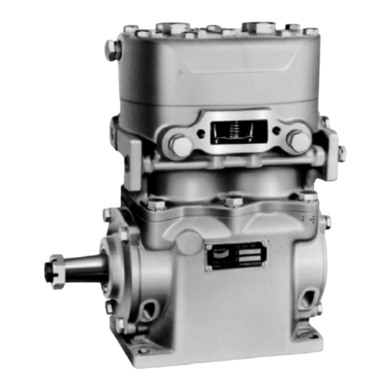
EXTERIOR
DESCRIPTION
The function of the air compressor is to provide and main-
tain air under pressure to operate devices in the air brake
and/or auxiliary air systems
The Tu-Flo
®
700 compressor is a two cylinder, single stage,
reciprocating compressor with a rated displacement of 15.5
cubic feet of air per minute at 1250 R.P.M. The Tu-Flo
compressor is constructed from three major assemblies,
the head, the cylinder block and the crankcase.
The head houses the discharge valving and is installed on
the upper portion of the cylinder block. The cylinder block
contains the cylinder bores and inlet valves and is mounted
to the crankcase. The crankcase houses the crankshaft
and main bearings.
Various mounting and drive configurations, required by the
numerous vehicle engine designs, are available. Two
governor mounting pads are located on either side of the
cylinder block to provide convenient governor mounting.
®
700 Air Compressor
D I S C H A R G E
VALVE SEAT
CONNECTING
D I S C H A R G E
CAP NUT
D I S C H A R G E
V A L V E
I N L E T
V A L V E
S P R I N G
I N L E T
V A L V E
P I S T O N
R I N G S
P I S T O N
CRANKSHAFT
R O D
CRANKCASE
BENDIX
Two methods are employed for cooling the Tu-Flo
compressor during operation. The cylinder head is
connected to the engine's cooling system, while the cylinder
has external fins for efficient air cooling.
®
All Tu-Flo
700 compressors utilize the engine's pressurized
oil system to lubricate the internal moving parts. A nameplate
is attached to the crankcase to identify the compressor.
®
700
The nameplate displays a Bendix piece number or in some
cases an engine or vehicle manufacturer's piece number,
along with a serial number.
MANUFACTURED BY
BENDIX
D I S C H A R G E
V A L V E
S P R I N G
®
®
TU-FLO
700 AIR COMPRESSOR
(CROSS SECTION)
TU-FLO 700
B W
NO.
SER
NO.
COMPRESSOR NAMEPLATE
U N L O A D E R
M E C H A N I S M
®
700
1
Advertisement
Table of Contents

Related Manuals for BENDIX TU-FLO 700 COMPRESSOR


Summary of Contents for BENDIX TU-FLO 700 COMPRESSOR
- Page 1 ® cubic feet of air per minute at 1250 R.P.M. The Tu-Flo The nameplate displays a Bendix piece number or in some compressor is constructed from three major assemblies, cases an engine or vehicle manufacturer’s piece number, the head, the cylinder block and the crankcase.
-
Page 2: Non-Compression Of Air (Unloaded)
MACK "FOXHEAD" CUMMINS VARIOUS COMPRESSOR MOUNTINGS DETROIT DIESEL MACK OPERATION reservoir into the cavity beneath the unloader pistons. This lifts the unloader pistons and plungers. The plungers move The compressor is driven by the vehicle engine and is up and hold the inlet valves off their seats (see Figure 4). operating continuously while the engine is running. -
Page 3: Duty Cycle
2 of Table A in the Troubleshooting section) assumes FIGURE 1B - DISCHARGE LINE SAFETY VALVE a compressor with a normal (less than 25%) duty cycle, operating in a temperate climate. See Bendix and/or other air dryer manufacturer guidelines as needed. - Page 4 "cut-out" setting. For vehicles with accessories that are sensitive to small FIGURE 2 - INTAKE ® amounts of oil, we recommend installation of a Bendix PuraGuard ® ™ oil coalescing filter, designed to minimize the amount of oil present.
- Page 5 COOLING DRY ELEMENT—PLEATED PAPER AIR STRAINER Air flowing through the engine compartment from the action Every 20,000 miles or 800 operating hours: of the engine’s fan and the movement of the vehicle assists in cooling the crankcase. Coolant flowing from the engine’s Remove the spring clips from either side of mounting baffle cooling system through connecting lines enters the and remove the cover.
-
Page 6: Removing And Disassembly
Every 24 months, 7200 operating hours or after each to the nearest authorized Bendix Distributor for a factory 200,000 miles: remanufactured compressor. If this is not possible, the compressor can be repaired using genuine Bendix... - Page 7 A convenient method to indicate the above relationship is to Discard the inlet valves (3) and springs (2), the discharge use a metal scribe to mark the parts with numbers or lines. valves (7), springs (8) and the discharge valve seats (6) if Do not use a marking method that can be wiped off or defective.
- Page 8 If the pistons are removed from the rod, inspect the bronze CYLINDER BLOCK wrist pin bushing. Press out and replace the bushing if it is Clean the carbon and dirt from the inlet and unloader excessively worn. (See inspection of parts) Discard the piston passages.
- Page 9 be rebored or honed oversize. Oversized pistons and piston rings are available in .010 in., .020 in. and .030 in. oversizes. Cylinder bores must be smooth, straight, and round. Clearance between the cast iron pistons and cylinder bores PISTON should be between .002 in. minimum and .004 in. maximum. RINGS .002 .004...
- Page 10 REPAIRS ASSEMBLY General Note: All torques specified in this manual are DISCHARGE VALVES, VALVE STOPS AND assembly torques and can be expected to fall off after SEATS assembly is accomplished. Do not retorque after initial assembly torques fall. If the discharge valve seats merely show signs of slight wear, they can be dressed by using a lapping stone, grinding To convert inch pounds of torque to foot pounds of torque, compound and grinding tool.
- Page 11 piston and secure same by inserting the new lockwire CYLINDER HEAD through the hole in piston and wrist pin and lock the wire by Install the inlet valve springs in the cylinder head by applying snapping the short 90 section into the lockwire hole in the a turning motion to the spring after it is in the head.
-
Page 12: Compressor Troubleshooting
® 8. Use only genuine Bendix replacement parts, COMPRESSOR TROUBLESHOOTING components and kits. Replacement hardware, IMPORTANT: The troubleshooting contained in this section tubing, hose, fittings, etc. must be of equivalent size, type and strength as original equipment and considers the compressor as an integrated component of... -
Page 13: Table Of Contents
This troubleshooting guide obsoletes and supersedes all previous published troubleshooting information relative to Bendix air compressors. Advanced Troubleshooting Guide for Air Brake Compressors The guide consists of an introduction to air brake charging system components, a table showing recommended vehicle maintenance schedules, and a troubleshooting symptom and remedy section with tests to diagnose most charging system problems. - Page 14 (less than 25%) duty cycle, system and lubricated by the engine oil supply. operating in a temperate climate. See Bendix and/or other air dryer manufacturer guidelines as needed. The compressor's unloader mechanism and governor (along with a synchro valve for the Bendix ®...
-
Page 15: Maintenance Schedule And Usage Guidelines (Table A)
Note: To help prevent discharge line freeze-ups, shorter discharge recommended every 250,000 miles. line lengths or insulation may be required in cold climates. (See Bendix Bulletins TCH-08-21 and TCH-08-22, included in Appendix B, for more information.) 5 For certain vehicles/applications, where turbo-charged inlet air is used, a smaller size... -
Page 16: Oil Test Card Results (1.0)
Do not use this card test to diagnose û compressor "oil passing" issues. They are subjective and error prone. Use only the Bendix Air System Inspection Cup (BASIC) test and the methods described in this guide for advanced troubleshooting. The Bendix ®... -
Page 17: Symptom
Return the vehicle to service. An optional kit (Bendix piece number 5011327 for the Bendix AD-IS ™ or AD-IP ™ ® air dryers, or 5003838 for the Bendix ® ™ AD-9 air dryer) is available to redirect the air dryer exhaust. -
Page 18: In The Supply Reservoir (4.0)
(1-800-247-2725) and been performed as in Column 3. speak to a Tech Team member.) ð Drain all air tanks into Bendix ® (b) If the vehicle maintenance has BASIC test been performed as recom- cup (Bendix Air System Inspection Cup). - Page 19 45 degree fitting. For more Kinked discharge line shown. information on how to help prevent discharge line freeze-ups, see Bendix Bulletins TCH-08-21 and TCH-08-22 (Appendix B). Shorter discharge line lengths or insulation may be required in cold climates.
-
Page 20: At The Valves (5.0)
Note: After replacing a compressor, investigated. Bendix compressors are designed to residual oil may take a considerable period have a 'dry' sump and the presence of excess oil in of time to be flushed from the air brake the crankcase can lead to oil carryover. -
Page 21: Slow Build (9.0)
Symptom: What it may indicate: What you should do: ð See engine service manual. A problem with engine or other engine 6.0 Excessive oil consumption in accessory. engine. The engine service manual has more information. ð Air dryers remove water and oil from the air 7.0 Oil present at Air brake charging system is air dryer cartridge... - Page 22 90 degree fitting, it may be changed to a straight or 45 degree fitting. For more information on how to help prevent discharge line freeze-ups, see Bendix Bulletins TCH-08-21 TCH-08-22 (Appendix B). Shorter discharge line lengths or insulation may be required in cold climates.
-
Page 23: Doesn't Build Air (10.0)
45 degree fitting. For more information on how to help prevent discharge line freeze-ups, see Bendix Bulletins TCH- 08-21 and TCH-08-22 (Appendix B). Shorter discharge line lengths or insulation may be required in cold climates. -
Page 24: Air Dryer
Symptom: What it may indicate: What you should do: ð Inspect delivery lines to reservoir for 12.0 Air dryer (a) Restriction between air dryer and safety valve reservoir. restrictions and repair as needed. releases air. ð Verify relief pressure is at vehicle or (b) Air dryer safety valve malfunction. -
Page 25: Leaks Air (16.0)
Symptom: What it may indicate: What you should do: ð Check for leaking, damaged or defective (a) Compressor leaks 16.0 Compressor connections or ports. leaks air compressor fittings, gaskets, etc. Repair or replace as necessary. ð Go to Test 6 on page 27. (b) Compressor unloader mechanism malfunction. -
Page 26: Oil Leakage At Head Gasket
Tests Test 1: Excessive Oil Leakage at the Head Gasket Exterior leaks at the head gasket are not a sign that oil is being passed into the air charging system. Oil weepage at the head gasket does not prevent the compressor from building air. LOOK Observe the amount of weepage from the head gasket. -
Page 27: Governor Malfunction
Test 6: Compressor Unloader Leakage off and charge the unloader port by allowing air Bendix ® Compressors: Park vehicle, chock pressure to enter the hose and unload the wheels, and follow all standard safety procedures. -
Page 28: Basic Test Information
YES, number of days was known (30 - 90 days) with a Bendix air dryer that are properly maintained.) If, in cold weather conditions, the 30 day air tank drain schedule is longer Replace the Compressor. If under warranty, follow standard procedures. - Page 29 Footnote 2: To get an accurate reading for the amount of oil collected during a 30 day period, ask the customer not to drain the air tanks before returning. (Note that 30-90 days is the recommended air tank drain schedule for vehicles equipped with a Bendix air dryer that are properly maintained.) If, in cold weather conditions, the 30 day air tank drain schedule is longer than the customer's usual draining interval, the customer...
- Page 30 Appendix A continued: Information about the BASIC Test Kit (Bendix P/N 5013711) ® Filling in the Checklist for the Bendix Air System Inspection Cup (BASIC) Test Note: Follow all standard safety precautions. For vehicles using a desiccant air dryer. STEP C - How to Use the BASIC Test 1.
- Page 31 Last 3 feet, including fitting at the end of the discharge line, must be insulated with ½ inch thick closed cell polyethylene pipe insulation. If the discharge line length must be less than 6 feet or greater than 16 feet, contact your local Bendix representative.
- Page 32 10-16 ft. ½ in. None If the discharge line length must be less than 10 feet or greater than 16 feet, contact your local Bendix representative. System Leakage Check the air brake system for excessive air leakage using the Bendix “Dual System Air Brake Test and Check List”...
- Page 33 Appendix B: Continued Technical Bulletin Bulletin No.: TCH-008-022 Effective Date: 1/1/1994 Page: 1 of 1 Additional Cold Weather Operation Tips for the Air Brake System Subject: Last year we published Bulletin PRO-08-21 which provided some guidelines for “winterizing” a vehicle air brake system.
- Page 36 BW1422 © 2004 Bendix Commercial Vehicle Systems LLC All rights reserved. 10/2004 Printed in U.S.A.