Table of Contents
Advertisement
Quick Links
®
®
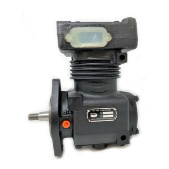
Bendix
BX-2150
UNLOADER
WATER
OUTLET
WATER
OUTLET
UNLOADER
PORTS
™
BX-2150
AIR COMPRESSOR BELT DRIVE MODEL
DESCRIPTION
GENERAL
The function of the air compressor is to provide and maintain
air under pressure to operate devices in the air brake and/or
auxiliary air systems.
DESCRIPTION
™
The BX-2150
compressor is a single cylinder, single stage
reciprocating compressor with a rated displacement of 9.5
™
Air Compressor
AIR OUTLET (2)
(1 NOT SHOWN)
STOP
WATER INLET
(NOT SHOWN)
AIR
INLET
INLET VALVE
AIR INTAKE
PISTON
CONNECTING
ROD
CRANKSHAFT
OIL SEAL
ROLLER
BEARING
CRANKSHAFT OIL PASSAGE
cubic feet per minute at 1250 R.P.M. The BX-2150
compressor is constructed from two major assemblies, the
cylinder head and the crankcase. The cylinder head is an
iron casting containing the inlet, discharge and unloader
valving. It is installed on the crankcase and is secured using
four cap screws symmetrically placed. The cylinder head
can be, therefore installed in any one of four different positions
which are 90° apart.
Two governor mounting surfaces, adjacent to the single
rectangular inlet cavity, provide a convenient means of
mounting the governor to the cylinder head. One eighth inch
UNLOADER
PISTON
DISCHARGE
PISTON
RINGS
REAR END
COVER
AIR OUTLET
VALVE
OIL INLET
SLEEVE
BEARING
™
1
Advertisement
Table of Contents
Troubleshooting

Related Manuals for BENDIX BX2150 AIR COMP-BW1424-


Summary of Contents for BENDIX BX2150 AIR COMP-BW1424-
-
Page 1: Air Compressor
® ® ™ Bendix BX-2150 Air Compressor AIR OUTLET (2) (1 NOT SHOWN) WATER INLET UNLOADER (NOT SHOWN) WATER STOP OUTLET INLET UNLOADER WATER PISTON OUTLET INLET VALVE UNLOADER PORTS AIR OUTLET AIR INTAKE DISCHARGE VALVE PISTON PISTON RINGS REAR END... - Page 2 A nameplate attached to the compressor crankcase identifies line returns the discharge valve to its seat. This prevents the the compressor model and is stamped to indicate the Bendix compressed air in the discharge line from returning to the part number and serial number.
- Page 3 2 of Table A in the Troubleshooting section) assumes a compressor with a normal (less than 25%) duty cycle, PISTON operating in a temperate climate. See Bendix and/or other air dryer manufacturer guidelines as needed. The discharge line must maintain a constant slope down from the compressor to the air dryer inlet fitting or reservoir to avoid low points where ice may form and block the flow.
- Page 4 (supply) reservoir. The oil droplets and the water collected are automatically purged when the governor reaches its "cut-out" setting. For vehicles with accessories that are sensitive to small ® amounts of oil, we recommend installation of a Bendix ® ™ PuraGuard oil coalescing filter, designed to minimize the amount of oil present.
- Page 5 The cylinder bore, connecting rod wrist pin bushing and ball type main bearing, where used, are splash lubricated. Splash OLD STYLE HEAD lubrication is obtained as oil is forced out around the ADAPTER REQUIRED crankshaft journals by engine oil pressure. See the tabulated technical data in the back of this manual for specific requirements.
- Page 6 Inlet gasket 243430 is required between the inlet check valve MOUNTING reed and the inlet cavity of new style heads, or between the BAFFLE FILTER COVER inlet check valve reed and the inlet adapter 297871 for old ELEMENT style heads, as its thickness contributes to the minimum reed travel required.
- Page 7 In addition, compressor build-up performance, or when it is suspected Bendix has developed the "Bendix Air System Inspection that the compressor is “cycling” between the load and Cup" or BASIC test to help substantiate suspected excessive unloaded modes due to unloader piston leakage.
- Page 8 DESCRIPTION Cylinder Head Assembly Governor Gasket Unloader Bushing O-Ring Unloader Piston Unloader Spring CYLINDER HEAD ASSY. Inlet Valve Gasket Inlet Valve Seat Inlet Valve Inlet Valve Spring Inlet Valve Stop Unloader Piston Stop Hex Head Screws O-Ring Inlet Strainer Gasket Discharge Valve Stop Discharge Valve Spring Discharge Valve...
- Page 9 5. Following vehicle manufacturer’s as to leakage, it is recommended that a genuine Bendix recommended procedures, deactivate the electrical unloader kit be installed and the cylinder head retested. system in a manner that safely removes all electrical DISCHARGE VALVE LEAKAGE power from the vehicle.
- Page 10 6. Remove the drive gear(s) or pulley from the compressor cylinder head body be replaced if it is determined that crankshaft using a gear puller. Inspect the pulley or the unloader piston bushing requires replacement. If gear and associated parts for visible wear or damage. this is not possible, the bushing can be pressed out of Since these parts are precision fitted, they must be the head using the same procedure presented in Step...
- Page 11 PISTONS CLEANING OF PARTS Check the piston for scores, cracks, or enlarged ring grooves; GENERAL replace the piston if any of these conditions are found. All parts should be cleaned in a good commercial grade Measure the diameter of the top of the piston and the top solvent and dried prior to inspection.
- Page 12 This will help the valve to seat and should reduce the leakage. With the air pressure still applied at It is generally recommended that genuine Bendix service the discharge port of the cylinder head, check for leakage parts and maintenance kits be used whenever the around the discharge valve stop exposed on the top of compressor is disassembled.
- Page 13 and ball bearing into place. Carefully press the crankshaft 2. Secure the cylinder head to the crankcase using the and ball bearing into the crankcase using an arbor press. four cylinder head cap screws. Torque the cap screws Make certain not to damage the oil seal, if the in a “X”...
- Page 14 TESTING REBUILT COMPRESSOR WATER PORT In order to properly bench testa compressor under operating conditions, a test rack for correct mounting, cooling, DISCHARGE PORT lubricating, and driving the compressor is necessary. Such tests are not compulsory if the unit has been carefully rebuilt WATER PORT by an experienced person.
- Page 15 This troubleshooting guide obsoletes and supersedes all previous published troubleshooting information relative to Bendix air compressors. Advanced Troubleshooting Guide for Air Brake Compressors The guide consists of an introduction to air brake charging system components, a table showing recommended vehicle maintenance schedules, and a troubleshooting symptom and remedy section with tests to diagnose most charging system problems.
- Page 16 (less than 25%) duty cycle, system and lubricated by the engine oil supply. operating in a temperate climate. See Bendix and/or other air dryer manufacturer guidelines as needed. The compressor's unloader mechanism and governor (along with a synchro valve for the Bendix ®...
- Page 17 Note: To help prevent discharge line freeze-ups, shorter discharge recommended every 250,000 miles. line lengths or insulation may be required in cold climates. (See Bendix Bulletins TCH-08-21 and TCH-08-22, included in Appendix B, for more information.) 5 For certain vehicles/applications, where turbo-charged inlet air is used, a smaller size...
- Page 18 Do not use this card test to diagnose û compressor "oil passing" issues. They are subjective and error prone. Use only the Bendix Air System Inspection Cup (BASIC) test and the methods described in this guide for advanced troubleshooting. The Bendix ®...
- Page 19 Return the vehicle to service. An optional kit (Bendix piece number 5011327 for the Bendix AD-IS ™ or AD-IP ™ ® air dryers, or 5003838 for the Bendix ® AD-9 ™ air dryer) is available to redirect the air dryer exhaust.
- Page 20 (1-800-247-2725) and been performed as in Column 3. speak to a Tech Team member.) ð Drain all air tanks into Bendix ® (b) If the vehicle maintenance has BASIC test been performed as recom- cup (Bendix Air System Inspection Cup).
- Page 21 45 degree fitting. For more Kinked discharge line shown. information on how to help prevent discharge line freeze-ups, see Bendix Bulletins TCH-08-21 and TCH-08-22 (Appendix B). Shorter discharge line lengths or insulation may be required in cold climates.
- Page 22 Note: After replacing a compressor, investigated. Bendix compressors are designed to residual oil may take a considerable period have a 'dry' sump and the presence of excess oil in of time to be flushed from the air brake the crankcase can lead to oil carryover.
- Page 23 Symptom: What it may indicate: What you should do: ð See engine service manual. 6.0 Excessive oil A problem with engine or other engine consumption in accessory. engine. The engine service manual has more information. ð Air dryers remove water and oil from the air 7.0 Oil present at Air brake charging system is air dryer cartridge...
- Page 24 90 degree fitting, it may be changed to a straight or 45 degree fitting. For more information on how to help prevent discharge line freeze-ups, see Bendix Bulletins TCH-08-21 TCH-08-22 (Appendix B). Shorter discharge line lengths or insulation may be required in cold climates.
- Page 25 45 degree fitting. For more information on how to help prevent discharge line freeze-ups, see Bendix Bulletins TCH- 08-21 and TCH-08-22 (Appendix B). Shorter discharge line lengths or insulation may be required in cold climates.
- Page 26 Symptom: What it may indicate: What you should do: ð Inspect delivery lines to reservoir for 12.0 Air dryer (a) Restriction between air dryer and safety valve reservoir. restrictions and repair as needed. releases air. ð Verify relief pressure is at vehicle or (b) Air dryer safety valve malfunction.
- Page 27 Symptom: What it may indicate: What you should do: ð Check for leaking, damaged or defective (a) Compressor leaks 16.0 Compressor connections or ports. compressor fittings, gaskets, etc. Repair leaks air or replace as necessary. ð Go to Test 6 on page 29. (b) Compressor unloader mechanism malfunction.
- Page 28 Tests Test 1: Excessive Oil Leakage at the Head Gasket Exterior leaks at the head gasket are not a sign that oil is being passed into the air charging system. Oil weepage at the head gasket does not prevent the compressor from building air. LOOK Observe the amount of weepage from the head gasket.
- Page 29 Test 6: Compressor Unloader Leakage ® off and charge the unloader port by allowing air Bendix Compressors: Park vehicle, chock pressure to enter the hose and unload the wheels, and follow all standard safety procedures. Remove the governor and install a fitting to the compressor.
- Page 30 YES, number of days was known (30 - 90 days) with a Bendix air dryer that are properly maintained.) If, in cold weather conditions, the 30 day air tank drain schedule is longer Replace the Compressor. If under warranty, follow standard procedures.
- Page 31 Footnote 2: To get an accurate reading for the amount of oil collected during a 30 day period, ask the customer not to drain the air tanks before returning. (Note that 30-90 days is the recommended air tank drain schedule for vehicles equipped with a Bendix air dryer that are properly maintained.) If, in cold weather conditions, the 30 day air tank drain schedule is longer than the customer's usual draining interval, the customer...
- Page 32 Appendix A continued: Information about the BASIC Test Kit (Bendix P/N 5013711) ® Filling in the Checklist for the Bendix Air System Inspection Cup (BASIC) Test Note: Follow all standard safety precautions. For vehicles using a desiccant air dryer. STEP C - How to Use the BASIC Test 1.
- Page 33 Last 3 feet, including fitting at the end of the discharge line, must be insulated with ½ inch thick closed cell polyethylene pipe insulation. If the discharge line length must be less than 6 feet or greater than 16 feet, contact your local Bendix representative.
- Page 34 10-16 ft. ½ in. None If the discharge line length must be less than 10 feet or greater than 16 feet, contact your local Bendix representative. System Leakage Check the air brake system for excessive air leakage using the Bendix “Dual System Air Brake Test and Check List”...
- Page 35 Appendix B: Continued Technical Bulletin Bulletin No.: TCH-008-022 Effective Date: 1/1/1994 Page: 1 of 1 Additional Cold Weather Operation Tips for the Air Brake System Subject: Last year we published Bulletin PRO-08-21 which provided some guidelines for “winterizing” a vehicle air brake system.
- Page 36 BW1424 © 2004 Bendix Commercial Vehicle Systems LLC All rights reserved. 9/2004 Printed in U.S.A.