Table of Contents
Advertisement
Quick Links
Safety • Assembly • Operation • Adjustments • Maintenance • Troubleshooting • Parts Lists • Warranty
OPERATOR'S MANUAL
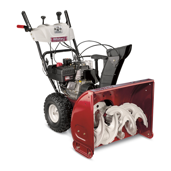
Two-Stage Snow Thrower
IMPORTANT:
READ SAFETY RULES AND
INSTRUCTIONS CAREFULLY
BEFORE OPERATION
MTD Products Ltd., P. O. Box 1386, KITCHENER, ONTARIO N2G 4J1
769-03246
PRINTED IN U.S.A.
08/22/07
Advertisement
Table of Contents

Related Manuals for MTD Yard-Man 31AE6GLF590


Summary of Contents for MTD Yard-Man 31AE6GLF590
- Page 1 Safety • Assembly • Operation • Adjustments • Maintenance • Troubleshooting • Parts Lists • Warranty OPERATOR’S MANUAL Two-Stage Snow Thrower IMPORTANT: READ SAFETY RULES AND INSTRUCTIONS CAREFULLY BEFORE OPERATION MTD Products Ltd., P. O. Box 1386, KITCHENER, ONTARIO N2G 4J1 769-03246 PRINTED IN U.S.A. 08/22/07...
-
Page 2: Table Of Contents
This Operator’s Manual is an important part of your new snow thrower. It will help you assemble, prepare and maintain the unit for best performance. Please read and understand what it says. Table of Contents Safety Labels ............3 Maintaining Your Snow Thrower ...... 16 Safe Operation Practices ........ -
Page 3: Safety Labels
Safety Labels WARNING This symbol points out important safety instructions which, if not followed, could endanger the per- sonal safety and/or property of yourself and others. Read and follow all instructions in this manual before attempting to operate this machine. Failure to comply with these instructions may A chute clean-out tool is fastened to the top... -
Page 4: Safe Operation Practices
WARNING: Engine Exhaust, some of its constituents, and certain vehicle compo- nents contain or emit chemicals known to State of California to cause cancer and birth defects or other reproductive harm. DANGER: This machine was built to be operated according to the safe operation practices in this manual. - Page 5 Operation Maintenance & Storage 1. Do not put hands or feet near rotating parts, in the 1. Never tamper with safety devices. Check their proper auger/impeller housing or chute assembly. Contact with the operation regularly. Refer to the maintenance and adjust- rotating parts can amputate hands and feet.
-
Page 6: Setting Up Your Snow Thrower
IMPORTANT: The snow thrower is shipped with oil and WITHOUT GASOLINE. After assembly, refer to separate engine manual for proper fuel and engine oil recommendations. 1. Observe the lower area of the snow thrower to be sure both cables are aligned with roller guides. Setting Up a. - Page 7 4. Finish securing chute control assembly to chute support bracket with wing nut and hex screw removed earlier. See Figure 3-4. Setting Up Your Snow Thrower CAUTION Figure 3-4 Prior to operating your snow thrower, refer to Auger Control Test on page 13. 5.
- Page 8 Drift Cutters (If Equipped) Drift cutters should be used when operating the snow thrower in heavy drift conditions. • On models so equipped, drift cutters and hardware are assembled to the auger housing inverted. See Figure 3-7. Setting Up • Remove the carriage bolts and wingnuts securing the drift cutters to the housing.
- Page 9 Clean-Out Tool The clean-out tool is mounted to the rear of the auger housing and is designed to clear a clogged chute. Refer Clean-Out to page 11 for instructions on how to properly use it. Tool NOTE: This item is fastened with a cable tie to the rear of the auger housing at the factory.
-
Page 10: Operating Your Snow Thrower
Know Your Snow Thrower Drive Control Shift Lever Four-Way Heated Handles Chute Control™ Switch (en option)† Auger Control Operating Headlight Your Snow Wheel Steering Control † Electric Start Button Thrower Gas Cap Oil Fill Engine Controls Recoil Starter Handle Electric Starter Outlet Primer Ignition WARNING... - Page 11 Auger Control • To change the direction in which snow is thrown, squeeze the button on the joy-stick and pivot the joy-stick to the right or to the left. • To change the angle/distance which snow is thrown, pivot the joy-stick forward or backward. Wheel Steering Controls Operating The left and right wheel steering controls are located on...
- Page 12 Gas & Oil Fill-Up 7. When disconnecting the extension cord, always unplug the end at the three-prong wall outlet before Service the engine with gasoline and oil as instructed in unplugging the opposite end from the snow thrower. the separate engine manual packed with your unit. Read instructions carefully.
- Page 13 NOTE: Keep the key in a safe place. The engine cannot 2. In a well-ventilated area, start the snow thrower start without the ignition key. engine as instructed on the previous page. Make sure the throttle is set in the FAST position. Recoil Starter 3.
-
Page 14: Makingadjustments
Shift Cable If the full range of speeds (forward and reverse) cannot be achieved, refer to the figure to the left and adjust the shift cable as follows: 1. Place the shift lever in the fastest forward speed position. Making 2. - Page 15 2. With the drive control released, there must be 1/8” clearance between the friction wheel and the drive pulley in all positions of the shift lever. 3. With the drive control engaged, the friction wheel must contact the drive pulley. See Figure 6-8. 4. If adjustment is necessary, loosen the lower hex nut Making on the drive cable index bracket and pivot the bracket upward or downward as necessary. Refer to Figure Adjustments 5-3. Tighten the lower hex nut to secure the bracket when correct adjustment is reached. 5. Reassemble the frame cover and return the unit back to its operating position. NOTE: If you placed plastic under the gas cap, be certain to remove it now. Skid Shoes The space between this shave plate and the ground can IMPORTANT Figure 5-4 - Standard Skid Shoe be adjusted. For close snow removal, place skid shoes in It is not recommended the low position. Use middle or high position when area to that you operate this be cleared is uneven. 1. Adjust skid shoes by loosening the four lock nuts snow thrower on gravel and carriage bolts and moving skid shoes to desired as loose gravel can be position. See Figure 5-4 or 5-5.
-
Page 16: Maintaining Your Snow Thrower
Engine Refer to the separate engine manual packed with your unit for all engine maintenance. Lubrication Engine Refer to the separate engine manual packed with your Maintaining unit for all engine lubrication instructions. Gear Shaft Your Snow The gear (hex) shaft should be lubricated at least once a season or after every 25 hours of operation. - Page 17 Auger Belt Replacement NOTE: Drain the gasoline from the snow thrower, or place a piece of plastic under the gas cap. To remove and replace your snow thrower’s auger belt, proceed as follows: 2. Carefully pivot the snow thrower up and forward so 1.
- Page 18 Drive Belt Replacement To remove and replace your snow thrower’s auger belt, proceed as follows: 1. Remove the plastic belt cover on the front of the engine by removing the two self-tapping screws. See Figure 6-4. Maintaining 2. Drain the gasoline from the snow thrower, or place a piece of plastic under the gas cap.
-
Page 19: Off-Season Storage
Observe the following, when preparing your snow thrower for off-season storage: • Drain fuel into an approved container outdoors, away from any open flame. Allow engine to cool. Extinguish cigarettes, cigars, pipes and other sources of ignition prior to draining fuel. Fuel left in engine during warm weather deteriorates and will cause serious starting Off-Season problems. -
Page 20: Trouble Shooting
Problem Cause Remedy 1. Choke not in ON position. 1. Move choke to ON position. Engine fails to start 2. Spark plug wire disconnected. 2. Connect wire to spark plug. 3. Fuel tank empty or stale fuel. 3. Fill tank with clean, fresh gasoline. 4. -
Page 21: Warranty
How to Obtain Service: Warranty service is available, with proof of purchase, through your local MTD Authorized Service Dealer. If you do not know the dealer in your area, please write to the Service Department of MTD PRODUCTS LIMITED, P.O. BOX 1386, KITCHENER, ONTARIO N2G 4J1. - Page 22 Optional/en option 34 35 42E 42B...
- Page 23 PART N° DE N° DE RÉF PIÈCE DE SCRIP TION DE SCRIP TION 710-1652 Hex Wash Hd TT Scr. 1/4-20 x .625 Vis taraudée 1/4-20 x 0,625 731-04792A Belt Cover (w/4 Way Chute Con trol) Couvre-courroie(avec comm. de la goulotte à 4 fonctions) 731-05353 Belt Cover (Std.) Couvre-courroie (Std.)
- Page 24 NOTE: Housing may not be exactly as shown. REMARQUE : L'habitacle peut être légèrement différent. 30 in/po...
- Page 25 PART N° DE N° DE RÉF PIÈCE DE SCRIP TION DE SCRIP TION 731-2643 Clean-Out Tool Outil de dégagement de la goulotte 684-04057A Impeller Ass'y 12 po Ventilateur 710-0347 Hex Screw 3/8-16 x 1.75 Vis à tête hex 3/8-16 x 1,75 710-0451 Carriage Bolt 5/16-18 x .75 Boulon ordi naire 5/16-18 x 0,75...
- Page 26 Model Number/ Numéro de modèle 31AE6GKF500 Style...
- Page 27 PART N° DE N° DE RÉF PIÈCE DE SCRIP TION DE SCRIP TION 631-04180 Handle Panel Ass’y - Yellow Panneau - jaune 631-04185 Handle Panel Ass’y - Black Panneau - noir 631-04183 Handle Panel Ass’y-Black w/Chute Con trol Panneau - noir avec comm. de la goulotte 631-04133A LH Clutch Lock Han dle Ass’y Poignée d’embrayage CG...
- Page 28 Manual Chute Control/ Commande de la goulotte manuelle...
- Page 29 PART N° DE N° DE RÉF PIÈCE DE SCRIP TION DE SCRIP TION 631-04131B Lower Chute (2 Way) Goulotte inférieur (2 fonctions) 731-04861B Lower Chute (4 Way) Goulotte inférieur (4 fonctions) 684-04117A 2 Way Chute Con trol As sembly Ens. - commande de la goulotte à 2 fonctions 684-04116B 4 Way Chute Con trol As sembly Ens.
- Page 30 Model Wheel As sem bly De scrip tion Tire Axle Modèle En sem ble de roue De scrip tion Roue Jante Essieu 31AE6GLF590 634-04145 16 x 4.8 x 8 LH X-Trac 734-2038 634-04173 738-04168 31AE6GLF596 634-04146 16 x 4.8 x 8 RH X-Trac 734-2038 634-04173 31AE6GLF597...