Table of Contents
Advertisement
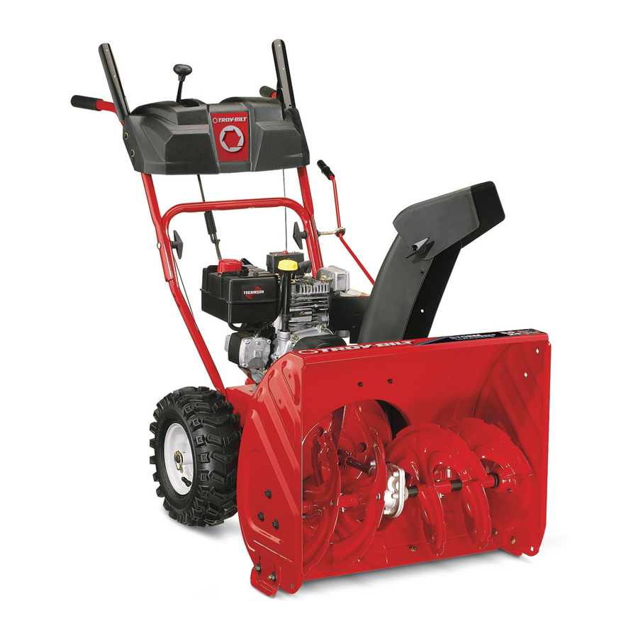
Service Manual
Model 31AS6BN2711 Two-Stage Snow Thrower
NOTE: These materials are for use by trained technicians who are experienced in the service and repair of outdoor power
equipment of the kind described in this publication, and are not intended for use by untrained or inexperienced individuals. These
materials are intended to provide supplemental information to assist the trained technician. Untrained or inexperienced individuals
should seek the assistance of an experienced and trained professional. Read, understand, and follow all instructions and common
sense when working on power equipment. This includes the contents of the product's Operators Manual, supplied with the
equipment. No liability can be accepted for any inaccuracies or omission in this publication, although care has been taken to make
it as complete and accurate as possible at the time of publication. However, due to the variety of outdoor power equipment and
continuing product changes that occur over time, updates will be made to these instructions from time to time. Therefore, it may
be necessary to obtain the latest materials before servicing or repairing a product. The company reserves the right to make
changes at any time to this publication without prior notice and without incurring an obligation to make such changes to previously
published versions. Instructions, photographs and illustrations used in this publication are for reference use only and may not
depict actual model and component parts. © Copyright 2005 MTD Products Inc. All Rights Reserved
MTD Products LLC - Product Training and Education Department
FORM NUMBER 769-01420
9/2004
Advertisement
Table of Contents

Related Manuals for MTD 31AS6BN2711


Summary of Contents for MTD 31AS6BN2711
- Page 1 Instructions, photographs and illustrations used in this publication are for reference use only and may not depict actual model and component parts. © Copyright 2005 MTD Products Inc. All Rights Reserved MTD Products LLC - Product Training and Education Department...
-
Page 3: Table Of Contents
SERVICE MANUAL 31AS6BN-711 Snow Thrower Tire Pressure ..........................1 Chute Installation .........................2 Discharge Chute Removal ......................2 Directional Control Assembly .......................2 Chute Bracket Adjustment ......................2 Skid Shoe and Shave Plate Adjustment ..................2 The Shave Plate Adjustment......................3 Drive Control Cable Adjustment ....................3 Auger Control Testing and Adjustment ..................4 Shift Rod Adjustment .........................5 Auger Belt Replacement ......................5 Drive Belt Replacement ......................7... -
Page 5: Service Manual 31As6Bn-711 Snow Thrower
SERVICE MANUAL 31AS6BN2-711 Snow Thrower 31AS6BN2711 (TROY-BILT AS SPECIFIED FOR Secure it in place by placing a rubber bushing over the LOWE’S top of the lower shift rod OR the upper shift rod. (A small piece of gas line can be used as a bushing.) This will prevent the sleeve from sliding up the shaft. -
Page 6: Chute Installation
NOTE: If the tire pressure is not equal in both tires, the 4.2. Insert the end of the chute directional control into unit may pull to one side or the other during operation. the lower bracket and secure with the flat washer and hairpin clip. -
Page 7: The Shave Plate Adjustment
Use a middle or lower position when the area to be 7.2. Reassemble the new shave plate, making sure cleared is uneven, such as a gravel driveway. the heads of the carriage bolts are to the inside of the housing. Tighten securely. See Figure 7. CAUTION: Loose gravel can be picked up and thrown by the auger, causing injury to the opera- tor and bystanders and/or damage to the snow... -
Page 8: Auger Control Testing And Adjustment
8.4. Loosen the hex jam nut on the auger control 9.4. To readjust the control cable, loosen the hex jam cable "Z" fitting and rotate the coupling end of nut on the auger control cable "Z" fitting. Rotate the cable downward to provide more slack or the coupling end of the cable counterclockwise upward to take up slack. -
Page 9: Shift Rod Adjustment
When replacing pins, spray an oil lubricant into shaft 11.1. Using a 3/8” socket and extension, remove the before inserting new pins. two self-tapping screws securing the plastic belt cover to the frame. See Figure 13. SHIFT ROD ADJUSTMENT If the full range of speeds (forward and reverse) cannot be achieved, adjust the shift rod. - Page 10 11.5. Using a 3/8” socket, remove the four self-tapping 11.7. Using a piece of starter cord, unhook the support screws which secure the frame cover to the bracket spring from the frame. See Figure 17. frame. See Figure 15. Shoulder Screw and Nut (Belt Keeper) Self Tapping Hex Screws Starter Cord...
-
Page 11: Drive Belt Replacement
DRIVE BELT REPLACEMENT FRICTION WHEEL REMOVAL To remove and replace your snow thrower's auger belt, If the snow thrower fails to drive with the drive control proceed as follows: engaged, and performing the drive control cable adjustment fails to correct the problem, the friction 12.1. - Page 12 13.6. Slide the hex shaft to the left while carefully un- 13.9. Inspect the friction wheel and all components of meshing the lower gears on the hex shaft from the hex shaft for any wear or damage. See Fig- the upper gears on the wheel axle. See Figure ure 24.
-
Page 13: Axle Shaft Removall
13.12. Reassemble the side plates with a replacement 14.4. Use a 7/16” socket and back off the screw secur- rubber ring. ing the cable roller to the guide bracket. Do not remove the screw. Slip the cable over the roller. IMPORTANT: Tighten each screw only one rota- See Figure 27. -
Page 14: Splitting The Unit
14.7. Slide the axle shaft to left to allow 44T gear to 15.3. Remove the hairpin clip securing the chute crank slide off the key. See Figure 29. assembly to the chute crank bracket. See Figure Axle Shaft Slide Left Hairpin Clip Washer Chute Crank... -
Page 15: Friction Wheel Disc Disassembly
15.9. Using a ½” socket remove the four hex screws 16.5. Using a screwdriver and 9/16” wrench, remove and bell washers securing the auger housing the jam nut and bell washer securing the friction assembly to the frame. wheel to the support bracket. See Figure 34. 15.10. -
Page 16: Auger And Impeller Removal
17.3. Using a 1/’2” socket, remove the screw and flat 18.3. Using a ½” socket, remove the two flange lock washer securing the auger pulley to the impeller nuts securing the bearing housing to the auger assembly. See Figure 36. housing. -
Page 17: Reducer Transmission
18.6. Carefully tip back and remove the housing from • Hex flange bearings are used at the ends of the the auger assembly. See Figure 39. auger axle. See Figure 41. Shear Pin Cotter Pin Hex Flange Bearing Spiral Figure 39 Figure 41 AUGER AND IMPELLER NOTES •... -
Page 18: Reduction Transmission Disassembly
20.2. Separate the housing halves using a putty knife. See Figure 45. NOTE: On the top of the gearbox is inspection and access hole for adding grease when and if required. Remove the rubber grommet from the lubrication port. See Figure 43. Rubber Grommet Ultra Gray Reducer Transmission... -
Page 19: Chute Disassembly
21.4. Using a 9/16’ socket on a long extension and a 22.5. Using a 7/16” socket, remove the four flange 15/16” socket on a ½’ socket wrench, remove lock nuts and washers securing the chute the nut and shoulder screw attaching the idler adapter to the auger housing.