
Related Manuals for ADC HRE-204 List 1


Summary of Contents for ADC HRE-204 List 1
- Page 1 HiGain HiGain ANUAL HRE-204 List 1 and List 2 HiGain Remote Enclosure Product Catalog: 150-204-100-03 CLEI: T1MF5004, T1MF6004...
- Page 2 Contents herein are current as of the date of publication. ADC reserves the right to change the contents without prior notice. In no event shall ADC be liable for any damages resulting from loss of data, loss of use, or loss of profits, and ADC further disclaims any and all liability for indirect, incidental, special, consequential or other similar damages.
- Page 3 Check the packing list to ensure complete and accurate shipment of each listed item. If the shipment is short or irregular, contact ADC DSL Systems, Inc. as described in Product Support on page 19. If you must store the equipment for a prolonged period, store the equipment in its original container.
- Page 4 Inspecting Shipment 150-204-100-03, Issue 3 May 7, 1999 HRE-204 List 1and List 2...
-
Page 5: Table Of Contents
Appendix A - Specifications____________________________________________________________ 17 Appendix B - Abbreviations ___________________________________________________________ 18 Appendix C - Product Support _________________________________________________________ 19 Bar Code and Configuration Number Information ................20 Certification and Warranty________________________________________________ Inside Back Cover HRE-204 List 1 and List 2 May 7, 1999... - Page 6 Figure 3. HRE-204 List 1 and List 2 Remote Enclosure ................. 4 Figure 4. Side Panel Assembly ........................5 Figure 5. HRE-204 List 1 and List 2 List 1 Backplate ..................6 Figure 6. Wall Mounting and Hinging View....................7 Figure 7.
-
Page 7: Overview
Remote Enclosure HRE-204 List 1 and List 2. The HRE-204 List 1 and List 2. List 1 and List 2 house HiGain Line Units (HLUs) and remote units (HRUs). The HRE-204 List 1 and List 2 List 1 has RJ48C DS1 connectors, and the HRE-204 List 1 and List 2 List 2 has RJ48X connectors. -
Page 8: Backplane
Overview 150-204-100-03, Issue 3 ACKPLANE Figure 1 shows the HRE-204 List 1 and List 2 backplane. Table 1 on page 3 describes its connectors. RJ48 jacks Figure 1. HRE-204 List 1 and List 2 Backplane May 7, 1999 HRE-204 List 1 and List 2... -
Page 9: Figure 2. Backplane Slot Connections
Slots 3 and 4 Terminal block connector for HLU alarm output interface Frame ground lug Figure 2 shows the backplane wiring connections to all four slots. Figure 2. Backplane Slot Connections HRE-204 List 1 and List 2 May 7, 1999... -
Page 10: Slot Connectors
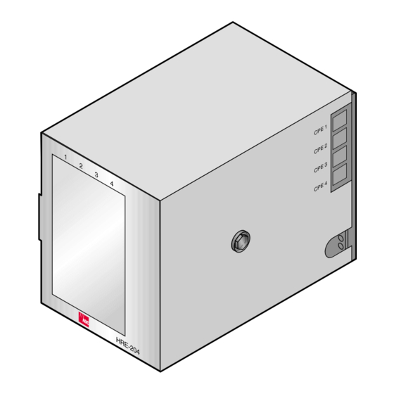
Units and HiGain Remote Units. Figure 3. HRE-204 List 1 and List 2 Remote Enclosure NSTALLATION This section provides information on installing and mounting the HRE-204 List 1 and List 2 List 1 and List 2. NSTALLATION • two mounting screws •... -
Page 11: Mounting Options
OUNTING PTIONS The HRE-204 List 1 and List 2 is suitable for mounting on a desktop or on a wall. Before setting up the equipment, select a location that will provide appropriate security. Regardless of where the HRE-204 List 1 and List 2 is mounted, ADC recommends that the frame ground lug be connected to earth ground according to the grounding recommendations found in Section 9 of Bellcore’s GR-1089-DEC, 1996. -
Page 12: Figure 5. Hre-204 List 1 And List 2 List 1 Backplate
Use the backplate as a template to mark the wall locations for drilling the mounting holes (Figure Figure 5. HRE-204 List 1 and List 2 List 1 Backplate Drill pilot holes and attach the backplate to the backboard with the two No. 10 x 5/8-inch sheet metal screws and washers supplied with the remote enclosure. -
Page 13: Figure 6. Wall Mounting And Hinging View
Unlatch the chassis from the two friction clasps in the upper corner of the backplate to lower it. See Figure 6 for hinging details. HRE-204 List 1 and List 2 May 7, 1999... -
Page 14: Optional Hinged Wall Mounting
Figure 7. Optional Mounting Hinge The two snap-in standoffs on the hinge bracket fit into two mounting holes in the HRE-204 List 1 and List 2 side panel when the enclosure is closed against the hinge. This secures the HRE-204 List 1 and List 2 to the hinge and prevents normal vibration from jarring it loose. -
Page 15: Turn-Up
OWER AND ROUNDING The chassis frame and pins 1 and 17 (slot frame ground) of each slot are connected to the HRE-204 List 1 and List 2 ground lug G1, located on the backplane, as shown in Figure 1 on page 2. -
Page 16: Figure 8. Tb3 And Tb4 Pin Assignments
Troncom WPS-4806 doublers) Troncom WPS-4810 HLU-431 24 Watts Troncom WPS-4806 (with 1000 Troncom WPS-4810 doublers) * Minimum input power lead wire size current capacity is based on 1000 circular mils per ampere. May 7, 1999 HRE-204 List 1 and List 2... -
Page 17: Pin Assignments
The following sections show the connector pin assignments of the HiGain plugs which are compatible with the HRE-204 List 1 and List 2. SSIGNMENTS Slot pin assignments for the various plugs compatible with the HRE-204 List 1 and List 2 are shown in the following figures: •... -
Page 18: Figure 10. Hlu-431 Pin Assignments
Pin Assignments 150-204-100-03, Issue 3 Figure 10. HLU-431 Pin Assignments May 7, 1999 HRE-204 List 1 and List 2... -
Page 19: Figure 11. Eru-412 Pin Assignments
Figure 11. ERU-412 Pin Assignments If you are installing HiGain-ETSI remote units in the HRE-204 List 1 and List 2, use only the 1209 G.703 ERU. The 75 9 G.703 ERU should not be used. The 75 9 interface requires BNC connectors that are not available in the HRE-204 List 1 and List 2. -
Page 20: Hlu Alarm Output Interface
NTERFACE When HLU-431 line units are installed in the HRE-204 List 1 and List 2, the system alarm relay contacts for each slot, Normally Open (NO) and Common (COM), are bused together and made available on the Euro style terminal block TB5. -
Page 21: Figure 14. Tb2 Pin Assignments
ALARMS display field when viewing the HiGain Status screen. This condition does not affect system operation, but should be corrected to avoid any confusion regarding the identities of the two HDSL loops. HRE-204 List 1 and List 2 May 7, 1999... -
Page 22: Cpe Ds1 (G.703) Connections
Figure 15 shows the pin assignments for the RJ48C jack. Figure 16 shows the RJ48X pin assignments. Figure 15. RJ48C Pin Assignments (List 1) Figure 16. RJ48X Pin Assignments (List 2) May 7, 1999 HRE-204 List 1 and List 2... -
Page 23: Appendix A - Specifications
4.8 in. (12 cm) Depth 7.5 in. (19 cm) Weight 3.0 lb (1.4 kg) Operating Temp: 0 °F to +158 °F (-18 °C to 70 °C) Humidity: 0 to 95% non-condensing Environment HRE-204 List 1 and List 2 May 7, 1999... -
Page 24: Appendixb - Abbreviations
ElectroMagnetic Interference ETSI European Telecommunications Standards Institute HiGain Card Shelf HiGain T1 Doubler Unit HiGain Remote Enclosure ICEA Insulated Cable Engineers Association Light Emitting Diode Rural Electrification Administration Return Material Authorization May 7, 1999 HRE-204 List 1 and List 2... -
Page 25: Appendix C - Product Support
UPPORT ADC Customer Service Group provides expert pre-sales and post-sales support and training for all its products. Technical support is available 24 hours a day, 7 days a week by contacting the ADC Technical Assistance Center (TAC). • Quotation Proposals Sales Assistance •... -
Page 26: Bar Code And Configuration Number Information
Equipment Catalog Item (ECI) bar code number. Bar code and configuration This label contains the configuration or revision number, the part number, the Julian date, and the number label bar code serial number. May 7, 1999 HRE-204 List 1 and List 2... - Page 27 150-204-100-03, Issue 3 Appendix C - Product Support HRE-204 List 1 and List 2 May 7, 1999...
-
Page 28: Certification And Warranty
ADC during the 90-day warranty period is, at ADC’s option, either (a) return of the price paid or (b) repair or replace of the software. ADC also warrants that, for a period of thirty (30) days from the date of purchase, the media on which software is stored will be free from material defects under normal use. - Page 29 ADC DSL Systems, Inc. 14402 Franklin Avenue Tustin, CA 92780-7013 Tel: 714.832.9922 Fax: 714.832.9924 Technical Assistance Tel: 800.638.0031 Tel: 714.730.3222 Fax: 714.730.2400 : 150-204-100-03, I OCUMENT SSUE ISO 9001/TL 9000 ´,3P¶8§¨ 1219488 DNV Certification, Inc. REGISTERED FIRM...