
Related Manuals for ADC HiGain HRE-420


Summary of Contents for ADC HiGain HRE-420
- Page 1 HiGain HiGain ANUAL HRE-420 Lists 1, 2, 3, and 4 HiGain Remote Indoor Enclosure Product Catalog: 150-1115-01, 150-1115-02, 150-1115-03, 150-1115-04 CLEI: T1RHC904MA (List 1), T1RHC9A4MA (List 2)
- Page 2 Contents herein are current as of the date of publication. ADC reserves the right to change the contents without prior notice. In no event shall ADC be liable for any damages resulting from loss of data, loss of use, or loss of profits, and ADC further disclaims any and all liability for indirect, incidental, special, consequential or other similar damages.
- Page 3 Unpack each container and inspect the contents for signs of damage. If the equipment has been damaged in transit, immediately report the extent of damage to the transportation company and to ADC DSL Systems, Inc. Order replacement equipment, if necessary.
- Page 4 Inspecting Shipment 100-420-100-04, Issue 4 November 21, 2003 HRE-420 Lists 1, 2, 3, and 4...
-
Page 5: Table Of Contents
100-420-100-04, Issue 4 Table of Contents ABLE OF ONTENTS Product Overview ..........................1 Description And Features ....................1 Applications.........................2 Specifications .............................2 Operating Temperature and Humidity.................2 Dimensions ..........................2 Certification ............................3 UL Listing..........................3 CSA Certification ........................3 Installation ...........................3 Installation Options and Wiring ......................4 Mounting............................5 Power and Ground Wiring .........................5 List 1 and 2 DS1/HDSL Interface Wiring for HRU-412 Domestic Applications ......6 HDSL Loop 1 and 2......................6... - Page 6 List of Tables 100-420-100-04, Issue 4 5. HRE-420, List 1 and 2 Block Diagram......................7 6. HRE-420, List 3 Printed Circuit Board and TB1 Pin Assignments..............9 7. HRE-420, List 3 Block Diagram ........................9 8. HRE-420, List 4 Printed Circuit Board and TB1 Pin Assignments............... 10 9.
-
Page 7: Product Overview
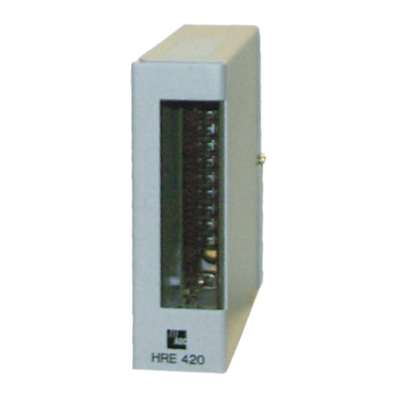
Figure 1. HRE-420 Enclosure (Front View) ADC’s HiGain Remote Indoor Enclosure model HRE-420 can accept either one single width, “400 or 200” mechanics type plugs (see Figure 1). The List 1 and 2 units have RJ-48C and RJ-48X DS1 interface connectors, respectively. -
Page 8: Applications
100-420-100-04, Issue 4 Table 1. Compatible Remote Plugs Model Document Catalog Number HRU-402, List 1 & 3 150-1592-100-xx HRU-402, List 1A 150-1592-111-xx HRU-402, List 4 LTPH-TP-1024-xx HRU-412, List 6 150-412-106-xx HRU-412, List 7 150-412-107-xx HRU-412, List 8 150-451-108-xx HRU-412, List 9 150-412-109-xx HRU-412, List 9B 150-412-192-xx... -
Page 9: Specifications
For performance and safety reasons, only power supplies listed for use with telephone equipment by a Nationally Recognized Testing Laboratory (NRTL) should be used with ADC equipment. Use of the HDU-451 or EDU-451 doubler units in the HRE-420 will void UL certification. -
Page 10: Installation Options And Wiring
Figure 2. HRE-420 Enclosures (Rear View) The ADC HRE-420 is a 1-slot wall mounted enclosure, which accepts one HiGain HRU-402 Remote Unit, one HiGain HRU-412 Remote Unit, or one HiGain HDU-451 Doubler Unit. The List 1 and 2 units are primarily intended for domestic use while the List 3 unit is used for International applications and the List 4 for Canadian applications. -
Page 11: Mounting
100-420-100-04, Issue 4 The tamper-proof screw can replace the factory provided blade “securing screw” shown in Figure 3. This screw requires an Allen key wrench, available on request, to install. It is intended to provide additional security if desired. The gummed Circuit Assignment Label is for circuit I.D.#. It can be attached to any convenient location on the enclosure. -
Page 12: List 1 And 2 Ds1/Hdsl Interface Wiring For Hru-412 Domestic Applications
100-420-100-04, Issue 4 2 DS1/HDSL I HRU-412 NTERFACE IRING FOR OMESTIC PPLICATIONS HDSL Loop 1 and 2 The HDSL LOOP 1 and 2 are the two HDSL pairs coming to the HRE-420 from the field cable pairs, see Figures 4 and 5. Connect HDSL LOOP 1 (IN) to TB1-3 (T) and TB1-4 (R). Connect HDSL LOOP 2 (IN) to TB1-5 (T1) and TB1-6 (R1). -
Page 13: Hdsl Loop 1 And 2
100-420-100-04, Issue 4 1, 2, 3, 4 HDSL I EDU-451 NTERFACE IRING FOR HDU-451 D OUBLER PPLICATIONS HDSL Loop 1 and 2 (IN) The HDSL LOOP 1 and 2 (IN) ports connect the two HDSL pairs coming to the HRE-420/doubler installation from the field cable pairs connected to the line unit, see Figures 4 through 9. -
Page 14: List 3 G.703 120 Ohm Interface Wiring For Eru-412 International Applications
100-420-100-04, Issue 4 3 G.703 120 O ERU-412 NTERFACE IRING FOR NTERNATIONAL PPLICATIONS HDSL Loop 1 and 2 (IN) Connections The HDSL LOOP 1 and 2 (IN) ports connect the two HDSL pairs coming to the HRE-420/ERU installation from the field cable pairs connected to the line unit, see Figures 6 and 7. Connect HDSL LOOP 1 (IN) to TB1-3 (T) and TB1-4 (R). - Page 15 100-420-100-04, Issue 4 Figure 6. HRE-420, List 3 Printed Circuit Board and TB1 Pin Assignments The diagram differentiates the List 3 unit by illustrating the two BNC connectors on the upper right hand side of the circuit board. Figure 7. HRE-420, List 3 Block Diagram HRE-420 Lists 1, 2, 3, and 4 November 21, 2003...
- Page 16 100-420-100-04, Issue 4 Figure 8. HRE-420, List 4 Printed Circuit Board and TB1 Pin Assignments The List 4 unit supports the Canadian DS1 interface requirements. LIST 4 Figure 9. HRE-420, List 4 Block Diagram November 21, 2003 HRE-420 Lists 1, 2, 3, and 4...
- Page 17 100-420-100-04, Issue 4 DS1 RCV RING 1 TIP 1 HDSL LOOP 2 OUT DS1 XMT RING HDSL LOOP 1 OUT Figure 10. List 1, RJ-48C Pin Assignments DS1 RCV RING 1 HDSL LOOP 2 OUT TIP 1 DS1 XMT RING HDSL LOOP 1 OUT Figure 11.
-
Page 18: Turn Up
Slide the HRU, ERU, HDU, or EDU card along the two card guides and into the edge connector as shown in Figure 13. It should be seated firmly in the connector. Refer to the appropriate ADC user manuals listed in Paragraph 1.01 for complete turn-up instructions. -
Page 19: Product Support
UPPORT ADC Customer Service Group provides expert pre-sales and post-sales support and training for all its products. Technical support is available 24 hours a day, 7 days a week by contacting the ADC Technical Assistance Center (TAC). • Quotation Proposals Sales Assistance •... - Page 20 100-420-100-04, Issue 4 November 21, 2003 HRE-420 Lists 1, 2, 3, and 4...
-
Page 21: Limited Warranty
90-day warranty period is, at ADC’s option, either (a) return of the price paid or (b) repair or replace of the software. ADC also warrants that, for a period of thirty (30) days from the date of purchase, the media on which software is stored will be free from material defects under normal use. - Page 22 World Headquarters ADC Telecommunications, Inc. PO Box 1101 Minneapolis, MN 55440-1101 For Technical Assistance Tel: 800.366-3891 x73223 Tel: 952.917.3223 Fax: 952.917.3244 ISO 9001/TL 9000 DNV Certification, Inc. REGISTERED FIRM : 100-420-100-04, I OCUMENT SSUE ´,nm¶6w¨ 1278776...