Table of Contents
Advertisement
Quick Links
Advertisement
Table of Contents

Related Manuals for Supermicro 2028R-E1CR24H


Summary of Contents for Supermicro 2028R-E1CR24H
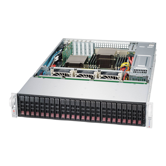
- Page 1 UPER TORAGE YSTEM 2028R-E1CR24H USER’S MANUAL...
- Page 2 This product, including software and docu- mentation, is the property of Supermicro and/or its licensors, and is supplied only under a license. Any use or reproduction of this product is not allowed, except as expressly permitted by the terms of said license.
- Page 3 SC216BE1C-R920LPB chassis. Chapter 2: Server Installation This chapter describes the steps necessary to install the 2028R-E1CR24H into a rack and check out the server configuration prior to powering up the system. If your server was ordered without processor and memory components, this chapter will refer you to the appropriate sections of the manual for their installation.
- Page 4 UPER TORAGE YSTEM 2028R-E1CR24H User's Manual Chapter 5: Advanced Serverboard Setup Chapter 5 provides detailed information on the X10DRH-iT serverboard, including the locations and functions of connections, headers and jumpers. Refer to this chapter when adding or removing processors or main memory and when reconfig- uring the serverboard.
- Page 5 Preface Notes...
-
Page 6: Table Of Contents
UPER TORAGE YSTEM 2028R-E1CR24H User's Manual Table of Contents Chapter 1 Introduction Overview ......................1-1 Serverboard Features ..................1-2 Processors ...................... 1-2 Memory ......................1-2 Main Storage Controller .................. 1-2 Serial ATA ......................1-2 PCI Expansion Slots ..................1-2 Rear I/O Ports ....................1-2 Onboard Graphics ................... - Page 7 Table of Contents Optional Quick Installation Method ..............2-9 Chapter 3 System Interface Overview ......................3-1 Control Panel Buttons ..................3-1 Reset ....................... 3-1 Power ......................3-1 Control Panel LEDs ..................3-1 Power Fail ....................... 3-2 Information LED ....................3-2 NIC1 ........................
- Page 8 UPER TORAGE YSTEM 2028R-E1CR24H User's Manual Installing a Passive CPU Heatsink ..............5-7 Removing the Heatsink ................... 5-7 Installing Memory .................... 5-8 Memory Support ....................5-8 DIMM Installation .................... 5-8 Adding PCI Expansion Cards ................5-11 Serverboard Details ..................5-12 X10DRH-iT Quick Reference ................ 5-13 Connector Definitions ...................
- Page 9 Table of Contents IPMI ....................... 7-42 Security Settings ................... 7-44 Boot Settings ....................7-45 Save & Exit ....................7-46 Appendix A BIOS POST Error Codes Appendix B System Specifications...
- Page 10 UPER TORAGE YSTEM 2028R-E1CR24H User's Manual Notes...
-
Page 11: Chapter 1 Introduction
Chapter 1 Introduction Overview The SuperStorageSystem 2028R-E1CR24H is comprised of two main subsys- tems: the SC216BE1C-R920LPB 2U chassis and the X10DRH-iT dual processor serverboard. Please refer to our website for information on operating systems that have been certified for use with the system (www.supermicro.com). -
Page 12: Serverboard Features
YSTEM 2028R-E1CR24H User's Manual Serverboard Features The SuperStorageSystem 2028R-E1CR24H is built around the X10DRH-iT, a dual processor serverboard based on the Intel C612 chipset. Below are the main features of the X10DRH-iT. (See Figure 1-1 for a block diagram of the chipset.) Processors The X10DRH-iT supports single or dual Intel®... -
Page 13: Onboard Graphics
Chapter 1: Introduction JBOD expansion ports. A UID (Unit Identifier) button and LED are also located beside the VGA port. Onboard Graphics Graphics are provided by an onboard ASpeed AST 2400 BMC, which supports IPMI. Server Chassis Features The following is a general outline of the main features of the SC216BE1C-R920LPB server chassis. - Page 14 UPER TORAGE YSTEM 2028R-E1CR24H User's Manual Figure 1-1. Intel C612 Chipset: System Block Diagram Note: This is a general block diagram. Please see Chapter 5 for details. X10DRH-C/i (T) #1-8 #2-8 #1-7 VCCP1 12v #2-7 #1-6 VR12.5 VR12.5 #2-6 #1-5...
-
Page 15: Contacting Supermicro
Super Micro Computer, Inc. 980 Rock Ave. San Jose, CA 95131 U.S.A. Tel: +1 (408) 503-8000 Fax: +1 (408) 503-8008 Email: marketing@supermicro.com (General Information) support@supermicro.com (Technical Support) Website: www.supermicro.com Europe Address: Super Micro Computer B.V. Het Sterrenbeeld 28, 5215 ML... - Page 16 UPER TORAGE YSTEM 2028R-E1CR24H User's Manual Notes...
-
Page 17: Chapter 2 Server Installation
Unpacking the System You should inspect the box the SuperServer 2028R-E1CR24H was shipped in and note if it was damaged in any way. If the server itself shows damage you should file a damage claim with the carrier who delivered it. -
Page 18: Warnings And Precautions
UPER TORAGE YSTEM 2028R-E1CR24H User's Manual • This product is for installation only in a Restricted Access Location (dedicated equipment rooms, service closets and the like). • This product is not suitable for use with visual display work place devices acccording to §2 of the the German Ordinance for Work with Visual Display Units. -
Page 19: Rack Mounting Considerations
Chapter 2: Server Installation Rack Mounting Considerations Ambient Operating Temperature If installed in a closed or multi-unit rack assembly, the ambient operating tempera- ture of the rack environment may be greater than the ambient temperature of the room. Therefore, consideration should be given to installing the equipment in an environment compatible with the manufacturer’s maximum rated ambient tempera- ture (Tmra). -
Page 20: Rack Mounting Instructions
UPER TORAGE YSTEM 2028R-E1CR24H User's Manual Rack Mounting Instructions This section provides information on installing the chassis into a rack unit with the rails provided. There are a variety of rack units on the market, which may mean that the assembly procedure will differ slightly from the instructions provided. You should also refer to the installation instructions that came with the rack unit you are using. -
Page 21: Locking Tabs
Chapter 2: Server Installation Locking Tabs Each inner rail has a locking tab. This tab locks the chassis into place when installed and pushed fully into the rack. These tabs also lock the chassis in place when fully extended from the rack. This prevents the server from coming completely out of the rack when when the chassis is pulled out for servicing. -
Page 22: Installing The Inner Rails On The Chassis
UPER TORAGE YSTEM 2028R-E1CR24H User's Manual Inner Rails Figure 2-3. Installing the Inner Rails Figure 2-4. Inner Rails Installed on the Chassis (The chassis above are an example only. Actual chassis may differ slightly) Installing The Inner Rails on the Chassis Installing the Inner Rails 1. -
Page 23: Installing The Outer Rails On The Rack
Chapter 2: Server Installation Figure 2-5. Extending and Releasing the Outer Rails Installing the Outer Rails on the Rack Installing the Outer Rails 1. Press upward on the locking tab at the rear end of the middle rail. 2. Push the middle rail back into the outer rail. 3. -
Page 24: Standard Chassis Installation
UPER TORAGE YSTEM 2028R-E1CR24H User's Manual Ball-Bearing Shuttle Figure 2-6. Installing into a Rack Standard Chassis Installation Installing the Chassis into a Rack 1. Confirm that the inner rails are properly installed on the chassis. 2. Confirm that the outer rails are correctly installed on the rack. -
Page 25: Optional Quick Installation Method
Chapter 2: Server Installation Optional Quick Installation Method The following quick installation method may be used to install the chassis onto a rack. Installing the Chassis into a Rack 1. Install the whole rail assembly onto the rack as described on page 2-7. 2. - Page 26 UPER TORAGE YSTEM 2028R-E1CR24H User's Manual Notes 2-10...
-
Page 27: Chapter 3 System Interface
Chapter 3: System Interface Chapter 3 System Interface Overview There are several LEDs on the control panel as well as others on the hard drive carriers to keep you constantly informed of the overall status of the system as well as the activity and health of specific components. -
Page 28: Power Fail
UPER TORAGE YSTEM 2028R-E1CR24H User's Manual Power Fail Indicates a power supply module has failed. The second power supply module will take the load and keep the system running but the failed module will need to be replaced. Refer to Chapter 6 for details on replacing the power supply. This LED should be off when the system is operating normally. -
Page 29: Nic2
Chapter 3: System Interface NIC2 Indicates network activity on the LAN2 port when flashing. On the SuperServer 2028R-E1CR24H, this LED indicates hard drive and/or DVD- ROM drive activity when flashing. Power Indicates power is being supplied to the system's power supply units. This LED should normally be illuminated when the system is operating. - Page 30 UPER TORAGE YSTEM 2028R-E1CR24H User's Manual Notes...
-
Page 31: Chapter 4 Standardized Warning Statements For Ac Systems
Only certified technicians should attempt to install or configure components. Read this appendix in its entirety before installing or configuring components in the Supermicro chassis. These warnings may also be found on our website at http://www.supermicro.com/ about/policies/safety_information.cfm. Warning Definition Warning! This warning symbol means danger. - Page 32 UPER TORAGE YSTEM 2028R-E1CR24H User's Manual Warnung WICHTIGE SICHERHEITSHINWEISE Dieses Warnsymbol bedeutet Gefahr. Sie befinden sich in einer Situation, die zu Verletzungen führen kann. Machen Sie sich vor der Arbeit mit Geräten mit den Gefahren elektrischer Schaltungen und den üblichen Verfahren zur Vorbeugung vor Unfällen vertraut.
- Page 33 Warning Statements for AC Systems جسذٌة اصابة ًتتسبب ف حالة ٌوكي أى ًاًك ف خطز ًٌٌع هذا الزهز !تحذٌز الذوائز بالوخاطز الٌاجوة عي ي على علن ، ك هعذات تعول على أي قبل أى الكهزبائٍة حىادث أي وقىع وٌع ل الىقائٍة...
-
Page 34: Installation Instructions
UPER TORAGE YSTEM 2028R-E1CR24H User's Manual Installation Instructions Warning! Read the installation instructions before connecting the system to the power source. 設置手順書 システムを電源に接続する前に、 設置手順書をお読み下さい。 警告 将此系统连接电源前,请先阅读安装说明。 警告 將系統與電源連接前,請先閱讀安裝說明。 Warnung Vor dem Anschließen des Systems an die Stromquelle die Installationsanweisungen lesen. -
Page 35: Circuit Breaker
Chapter 4: Warning Statements for AC Systems Circuit Breaker Warning! This product relies on the building's installation for short-circuit (overcurrent) protection. Ensure that the protective device is rated not greater than: 250 V, 20 A. サーキッ ト ・ ブレーカー この製品は、 短絡 (過電流) 保護装置がある建物での設置を前提としています。 保護装置の定格が250 V、... -
Page 36: Power Disconnection Warning
UPER TORAGE YSTEM 2028R-E1CR24H User's Manual في التي تم تثبيتها مه الدوائرالقصيرة الحمايت معداث يعتمد على هذا المنتج المبنى أكثر من ليس وقائي ال الجهاز تقييم أن تأكد من 20A, 250V 경고! 이 제품은 전원의 단락(과전류)방지에 대해서 전적으로 건물의 관련 설비에... - Page 37 Chapter 4: Warning Statements for AC Systems Warnung Das System muss von allen Quellen der Energie und vom Netzanschlusskabel getrennt sein, das von den Spg.Versorgungsteilmodulen entfernt wird, bevor es auf den Chassisinnenraum zurückgreift, um Systemsbestandteile anzubringen oder zu entfernen. ¡Advertencia! El sistema debe ser disconnected de todas las fuentes de energía y del cable eléctrico quitado de los módulos de fuente de alimentación antes de tener acceso el interior del chasis para instalar o para quitar componentes de sistema.
-
Page 38: Equipment Installation
UPER TORAGE YSTEM 2028R-E1CR24H User's Manual Equipment Installation Warning! Only trained and qualified personnel should be allowed to install, replace, or service this equipment. 機器の設置 トレーニングを受け認定された人だけがこの装置の設置、 交換、 またはサービスを許可 されています。 警告 只有经过培训且具有资格的人员才能进行此设备的安装、更换和维修。 警告 只有經過受訓且具資格人員才可安裝、更換與維修此設備。 Warnung Das Installieren, Ersetzen oder Bedienen dieser Ausrüstung sollte nur geschultem, qualifiziertem Personal gestattet werden. -
Page 39: Restricted Area
Chapter 4: Warning Statements for AC Systems Waarschuwing Deze apparatuur mag alleen worden geïnstalleerd, vervangen of hersteld door geschoold en gekwalificeerd personeel. Restricted Area Warning! This unit is intended for installation in restricted access areas. A restricted access area can be accessed only through the use of a special tool, lock and key, or other means of security. -
Page 40: Battery Handling
UPER TORAGE YSTEM 2028R-E1CR24H User's Manual אזור עם גישה מוגבלת !אזהרה יש להתקין את היחידה באזורים שיש בהם הגבלת גישה. הגישה ניתנת בעזרת .)'כלי אבטחה בלבד (מפתח, מנעול וכד محظورة مناطق ٍنتركُبها ف هذه انىحذة تخصيص تم ،أداة خاصت من خالل استخذاو... - Page 41 Chapter 4: Warning Statements for AC Systems Warnung Bei Einsetzen einer falschen Batterie besteht Explosionsgefahr. Ersetzen Sie die Batterie nur durch den gleichen oder vom Hersteller empfohlenen Batterietyp. Entsorgen Sie die benutzten Batterien nach den Anweisungen des Herstellers. Attention Danger d'explosion si la pile n'est pas remplacée correctement. Ne la remplacer que par une pile de type semblable ou équivalent, recommandée par le fabricant.
-
Page 42: Redundant Power Supplies
UPER TORAGE YSTEM 2028R-E1CR24H User's Manual Redundant Power Supplies Warning! This unit might have more than one power supply connection. All connections must be removed to de-energize the unit. 冗長電源装置 このユニッ トは複数の電源装置が接続されている場合があります。 ユニッ トの電源を切るためには、 すべての接続を取り外さなければなりません。 警告 此部件连接的电源可能不止一个,必须将所有电源断开才能停止给该部件供电。 警告 此裝置連接的電源可能不只一個,必須切斷所有電源才能停止對該裝置的供電。 Warnung Dieses Gerät kann mehr als eine Stromzufuhr haben. -
Page 43: Backplane Voltage
Chapter 4: Warning Statements for AC Systems امداد الطاقة بوحدات عدة اتصاالت جهاز ال يكون لهذا قد الكهرباء عن وحدة ال لعسل كافة االتصاالت يجب إزالة 경고! 이 장치에는 한 개 이상의 전원 공급 단자가 연결되어 있을 수 있습니다. 이 장치에 전원을... -
Page 44: Comply With Local And National Electrical Codes
UPER TORAGE YSTEM 2028R-E1CR24H User's Manual Attention Lorsque le système est en fonctionnement, des tensions électriques circulent sur le fond de panier. Prendre des précautions lors de la maintenance. מתח בפנל האחורי !הרה אז קיימת סכנת מתח בפנל האחורי בזמן תפעול המערכת. יש להיזהר במהלך... -
Page 45: Product Disposal
Chapter 4: Warning Statements for AC Systems ¡Advertencia! La instalacion del equipo debe cumplir con las normas de electricidad locales y nacionales.Attention L'équipement doit être installé conformément aux normes électriques nationales et locales. תיאום חוקי החשמל הארצי !אזהרה הציוד חייבת להיות תואמת לחוקי החשמל המקומיים והארציים התקנת... -
Page 46: Hot Swap Fan Warning
UPER TORAGE YSTEM 2028R-E1CR24H User's Manual Warnung Die Entsorgung dieses Produkts sollte gemäß allen Bestimmungen und Gesetzen des Landes erfolgen. ¡Advertencia! Al deshacerse por completo de este producto debe seguir todas las leyes y reglamentos nacionales. Attention La mise au rebut ou le recyclage de ce produit sont généralement soumis à des lois et/ou directives de respect de l'environnement. - Page 47 Chapter 4: Warning Statements for AC Systems 当您从机架移除风扇装置,风扇可能仍在转动。小心不要将手指、螺丝起子和其他 物品太靠近风扇 警告 當您從機架移除風扇裝置,風扇可能仍在轉動。小心不要將手指、螺絲起子和其他 物品太靠近風扇。 Warnung Die Lüfter drehen sich u. U. noch, wenn die Lüfterbaugruppe aus dem Chassis genommen wird. Halten Sie Finger, Schraubendreher und andere Gegenstände von den Öffnungen des Lüftergehäuses entfernt. ¡Advertencia! Los ventiladores podran dar vuelta cuando usted quite ell montaje del ventilador del chasis.
-
Page 48: Power Cable And Ac Adapter
Electrical Appliance and Material Safety Law prohibits the use of UL or CSA -certified cables (that have UL/CSA shown on the code) for any other electrical devices than products designated by Supermicro only. 電源コードとACアダプター 製品を設置する場合、 提供または指定された接続ケーブル、 電源コードとACアダプター... - Page 49 Appareils électroménagers et de loi sur la sécurité Matériel interdit l'utilisation de UL ou CSA câbles certifiés qui ont UL ou CSA indiqué sur le code pour tous les autres appareils électriques que les produits désignés par Supermicro seulement.
- Page 50 Elektrisch apparaat en veiligheidsinformatiebladen wet verbiedt het gebruik van UL of CSA gecertificeerde kabels die UL of CSA die op de code voor andere elektrische apparaten dan de producten die door Supermicro alleen. 4-20...
-
Page 51: Chapter 5 Advanced Serverboard Setup
Chapter 5: Advanced Serverboard Setup Chapter 5 Advanced Serverboard Setup This chapter is provided as a reference and describes the data and power cable connections and add-on cards. All serverboard jumpers and connections are also described. A layout and quick reference chart are included in this chapter for your reference. -
Page 52: Connecting Cables
UPER TORAGE YSTEM 2028R-E1CR24H User's Manual Connecting Cables Several cables need to be connected to the serverboard. These include the data cables for the peripherals and control panel and the power cables. Connecting Data Cables The cables used to transfer data from the peripheral devices have been carefully routed to prevent them from blocking the flow of cooling air that moves through the system from front to back. -
Page 53: Rear I/O Ports
Chapter 5: Advanced Serverboard Setup Figure 5-1. Control Panel Header Pins Power Button Ground Ground Reset Button Power Fail LED 3.3V OH/Fan Fail/ UID LED PWR Fail LED) NIC2 Activity LED NIC2 Link LED NIC1 Activity LED NIC1 Link LED UID Switch HDD LED FP PWRLED... -
Page 54: Installing The Processor And Heatsink
CPU socket cap is in place and none of the socket pins are bent; otherwise, contact your retailer immediately. • Refer to the Supermicro web site for updates on CPU support. Installing an LGA2011 Processor Press down on the lever labeled 'Close 1st' 1. - Page 55 Chapter 5: Advanced Serverboard Setup 3. With the lever labeled 'Close 1st' fully retracted, gently push down on the 'Open 1st' lever to open the load plate. Lift the load plate to open it completely. Gently push 4. Using your thumb and the index down to pop the load plate finger, remove the 'WARNING'...
- Page 56 UPER TORAGE YSTEM 2028R-E1CR24H User's Manual Warning: You can only install the CPU to the socket in one direction. Make sure that the CPU is properly inserted into the socket before closing the load plate. If it doesn't close properly, do not force it as it may damage your CPU. Instead, open the load plate again and double-check that the CPU is aligned properly.
-
Page 57: Installing A Passive Cpu Heatsink
Chapter 5: Advanced Serverboard Setup Installing a Passive CPU Heatsink 1. Do not apply any thermal grease to the heatsink or the CPU die. The required amount has already been applied. 2. Place the heatsink on top of the CPU so that the four mounting holes are aligned with those on the serverboard and the heatsink bracket underneath. -
Page 58: Installing Memory
UPER TORAGE YSTEM 2028R-E1CR24H User's Manual Installing Memory Caution: Exercise extreme care when installing or removing DIMM modules to prevent any possible damage. Memory Support The X10DRH-iT has 16 DIMM slots that can support up to 1024 GB of Load Re- duced (LRDIMM) or 512 GB of Registered (RDIMM) ECC DDR4-2133/1866/1600 memory. - Page 59 Chapter 5: Advanced Serverboard Setup Processor & Memory Module Population Configuration For the memory to work properly, follow the tables below for correct installation. Processors and their Corresponding Memory Modules CPU# Corresponding DIMM Modules CPU 1 DIMMA1 DIMMB1 DIMMC1 DIMMD1 DIMMA2 DIMMB2 DIMMC2...
- Page 60 UPER TORAGE YSTEM 2028R-E1CR24H User's Manual 1 CPU, 2 DIMMs 1 CPU, 4 DIMMs 1 CPU, 6 or 8 DIMMs BAR CODE BAR CODE BAR CODE MAC CODE MAC CODE MAC CODE X10DRH-C/i(T) X10DRH-C/i(T) X10DRH-C/i(T) Rev. 1.00 Rev. 1.00 Rev. 1.00...
-
Page 61: Adding Pci Expansion Cards
2133 Adding PCI Expansion Cards The 2028R-E1CR24H can accommodate up to five PCI expansion cards in the PCI INTEL CONFIDENTIAL Intel and the Intel logo are trademarks or registered trademarks of Intel Corporation or its subsidiaries in the United States and other countries. Other names and bran may be claimed as the property of others. -
Page 62: Serverboard Details
PCI slot. " " indicates the position of pin 1. The 2028R-E1CR24H comes pre-installed with a Hardware RAID controller installed in PCI-E slot 2 and a JBOD expansion port installed in PCI-E slot 1. The LSI 3108 is not included as an onboard component. -
Page 63: X10Drh-It Quick Reference
Chapter 5: Advanced Serverboard Setup X10DRH-iT Quick Reference Jumper Description Default Setting Clear CMOS/Reset BIOS Configuration JBT1 See Section 5-9 C1/JI C2 SMB to PCI-E Slots Pins 2-3 (Disabled) JPB1 BMC Enable/Disable Pins 1-2 (Enabled) JPG1 VGA Enable/Disable Pins 1-2 (Enabled) JPL1 TLAN1/TLAN2 Enable/Disable Pins 1-2 (Enabled) -
Page 64: Connector Definitions
UPER TORAGE YSTEM 2028R-E1CR24H User's Manual Connector Definitions ATX Power 24-pin Connector Pin Definitions Pin# Definition Pin # Definition Power Connectors +3.3V +3.3V -12V +3.3V A 24-pin main power supply connec- tor (J24) and two 8-pin CPU power PS_ON connectors (JPWR1/JPWR2) must be connected to the power supplyto pro- vide adequate power to the system. - Page 65 Chapter 5: Advanced Serverboard Setup Power Fail LED PWR Fail LED Pin Definitions (JF1) The Power Fail LED connection is Pin# Definition located on pins 5 and 6 of JF1. Re- 3.3V fer to the table on the right for pin definitions.
- Page 66 UPER TORAGE YSTEM 2028R-E1CR24H User's Manual Power On LED Power LED Pin Definitions (JF1) The Power On LED connector is lo- Pin# Definition cated on pins 15 and 16 of JF1 (use 3.3V JLED for a 3-pin connector). This PWR LED...
- Page 67 Chapter 5: Advanced Serverboard Setup Internal Speaker Internal Buzzer (SP1) Pin Definition The internal speaker, located at SP1, Pin# Definitions can be used to provide audible indica- Pin 1 Pos. (+) Beep In tions for various beep codes. See the Pin 2 Neg.
- Page 68 UPER TORAGE YSTEM 2028R-E1CR24H User's Manual Back Panel USB 0/1 (2.0) Pin Definitions Pin# Definition Pin# Definition USB_PN1 USB_PN0 USB_PP1 USB_PP0 Ground Ground Front Panel USB 2/3 (2.0) Pin Definitions Universal Serial Bus (USB) Pin # Definition Pin # Definition Two USB 3.0 and two USB 2.0 ports...
- Page 69 Blue: On of a system unit that may be in need of service. Note: UID can also be triggered via IPMI. For more information on IPMI, please refer to the IPMI User's Guide posted on our website at http://www.supermicro.com. 5-19...
- Page 70 UPER TORAGE YSTEM 2028R-E1CR24H User's Manual TPM/Port 80 Header Pin Definitions Pin # Definition Pin # Definition TPM Header/Port 80 LCLK A Trusted Platform Module/Port 80 LFRAME# <(KEY)> header is located at JTPM1 to provide LRESET# +5V (X) TPM support and a Port 80 connec-...
-
Page 71: Jumper Settings
Chapter 5: Advanced Serverboard Setup Jumper Settings Explanation of Jumpers To modify the operation of the serverboard, jumpers can be used Connector to choose between optional settings. Pins Jumpers create shorts between two pins to change the function of the con- nector. - Page 72 UPER TORAGE YSTEM 2028R-E1CR24H User's Manual LAN Enable/Disable GLAN Enable Jumper Settings JPL1 enables or disables the Gb LAN Jumper Setting Definition ports on the serverboard. See the Pins 1-2 Enabled table on the right for jumper settings. Pins 2-3 Disabled The default setting is Enabled.
- Page 73 Chapter 5: Advanced Serverboard Setup Watch Dog Enable/Disable Jumper JWD1 controls the Watch Dog function. Watch Dog is a sys- tem monitor that can reboot the system when a software application hangs. Jumping pins 1-2 will cause Watch Dog WD to reset the system if an appli- Jumper Settings cation hangs.
-
Page 74: 5-10 Onboard Indicators
UPER TORAGE YSTEM 2028R-E1CR24H User's Manual 5-10 Onboard Indicators LAN LEDs The Ethernet ports (located beside the LAN1/2 LED VGA port) have two LEDs. On each (Connection Speed Indicator) port, the green LED flashes to indicate LED Color Definition activity while the other LED may be... -
Page 75: 5-11 Sata Ports
Intel PCH C612 while the other four are supported by the Intel SCU and are located on a vertical S-SATA connector. Note: For more information on SATA HostRAID configuration, please refer to the Intel SATA HostRAID User's Guide posted on our website at http://www.supermicro. com.. 5-25... -
Page 76: 5-12 Installing Software
TORAGE YSTEM 2028R-E1CR24H User's Manual 5-12 Installing Software The Supermicro ftp site contains drivers and utilities for your system at ftp://ftp. supermicro.com. Some of these must be installed, such as the chipset driver. After accessing the ftp site, go into the CDR_Images directory and locate the ISO file for your serverboard. -
Page 77: Superdoctor® 5
Chapter 5: Advanced Serverboard Setup SuperDoctor® 5 The Supermicro SuperDoctor 5 is a program that functions in a command-line or web-based interface in Windows and Linux operating systems. The program moni- tors system health information such as CPU temperature, system voltages, system power consumption, fan speed, and provides alerts via email or Simple Network Management Protocol (SNMP). -
Page 78: 5-13 Onboard Battery
UPER TORAGE YSTEM 2028R-E1CR24H User's Manual 5-13 Onboard Battery Care must be taken to assure that the chassis cover is in place when the system is operating to assure proper cooling. Out of warranty damage to the system can occur if this practice is not strictly followed. -
Page 79: Chapter 6 Advanced Chassis Setup
Chapter 6: Advanced Chassis Setup Chapter 6 Advanced Chassis Setup This chapter covers the steps required to install components and perform main- tenance on the SC216BE1C-R920LPB chassis. For component installation, follow the steps in the order given to eliminate the most common problems encountered. If some steps are unnecessary, skip ahead to the step that follows. -
Page 80: Control Panel
UPER TORAGE YSTEM 2028R-E1CR24H User's Manual Figure 6-1. Front and Rear Chassis Views Hard Drives (24) Control Panel Note: numbers indicate the logical drive bay locations/. RAID Controller Card JBOD Expansion Ports Power Supplies (2) 7 Low-profile PCI Slots I/O Ports (see Figure 5-2) Optional 2.5"... -
Page 81: Removing The Chassis Cover
Chapter 6: Advanced Chassis Setup Removing the Chassis Cover Remove this screw (if necessary) Release Tab Figure 6-2. Removing the Chassis Cover Removing the Chassis Cover You may need to gain access to the inside of the server to perform various main- tenance tasks. -
Page 82: System Cooling
UPER TORAGE YSTEM 2028R-E1CR24H User's Manual System Cooling System Fans Three 8-cm hot-swap chassis fans provide the cooling for the SuperServer 2028R- E1CR24H. It is very important that the chassis top cover is properly installed in order for the cooling air to circulate properly through the chassis and cool the components. -
Page 83: Air Shrouds
Chapter 6: Advanced Chassis Setup Figure 6-3. Replacing System Cooling Fans Air Shrouds Air shrouds concentrate airflow to maximize fan efficiency. The SC216 chassis air shrouds do not require screws for installation. Installing the Air Shrouds in the Chassis Installing the Main Air Shroud 1. - Page 84 UPER TORAGE YSTEM 2028R-E1CR24H User's Manual An additional air shroud is required for high-powered CPUs, to provide extra cooling. Install the additional air shroud if necessary. Installing the Additional Air Shroud 1. Remove the left side break-away piece of the main air shroud.
-
Page 85: Drive Bay Installation/Removal
You do not need to access the inside of the chassis or remove power to replace or swap SAS or SATA drives. Proceed to the next step for instructions. Note: You must use 2.5" drives in the SuperServer 2028R-E1CR24H. The chassis supports 24 hot-swappable hard drives. Only enterprise level SAS or SATA HDDs are recommended for use in the SC216 chassis. - Page 86 Warning: Enterprise level hard disk drives are recommended for use in Supermicro chassis and servers. For information on recommended HDDs, visit the Supermicro website at http://www.supermicro.com/products/nfo/files/storage/SAS-1-Com-...
- Page 87 Chapter 6: Advanced Chassis Setup Figure 6-6. Mounting a SATA Drive in a Carrier Figure 6-7. Installing a Drive Carrier into a Hard Drive Bay...
-
Page 88: Power Supply
TORAGE YSTEM 2028R-E1CR24H User's Manual Power Supply The 2028R-E1CR24H chassis has two redundant, hot-plug 920 Watt power sup- plies. The power modules are hot-swappable, enabling them to be changed without powering down the system. These power supplies are auto-switching capable, allowing them to automatically sense and operate at a 100v to 240v input voltage. - Page 89 Chapter 6: Advanced Chassis Setup Changing the Power Supply 1. Determine which power supply needs to be replaced and unplug the power cord to that module. 2. Push the release tab (on the back of the power supply) as illustrated, to release the power module from the chassis.
-
Page 90: Attaching A Jbod Expansion Chassis
YSTEM 2028R-E1CR24H User's Manual Attaching a JBOD Expansion Chassis The SSG-2028R-E1CR24H features dual JBOD expansion ports. The JBOD attach- ment will vary depending on the specific JBOD chassis that is being connected. A two cable attachment (x8 SAS lanes) is recommended Figure 6-9. -
Page 91: Chapter 7 Bios
When an option is selected in the left frame, it is highlighted in white. Often a text message will accompany it. Note: the AMI BIOS has default text messages built in. Supermicro retains the option to include, omit, or change any of these text messages. -
Page 92: How To Start The Setup Utility
Flashing the wrong BIOS can cause irreparable damage to the system. In no event shall Supermicro be liable for direct, indirect, special, incidental, or consequential damages arising from a BIOS update. If you have to update the BIOS, do not shut down or reset the system while the BIOS is updating to avoid possible boot failure. - Page 93 Note: The time is in the 24-hour format. For example, 5:30 P.M. appears as 17:30:00. Supermicro X10DRH-C/i Version: This item displays the version of the BIOS ROM used in the system. Build Date: This item displays the date when the version of the BIOS ROM used in the system was built.
-
Page 94: Advanced Setup Configurations
UPER TORAGE YSTEM 2028R-E1CR24H User's Manual Advanced Setup Configurations Use the arrow keys to select Advanced setup and press <Enter> to access the submenu items: Warning: Use caution when changing the Advanced settings. An incorrect value, a very high DRAM frequency or an incorrect BIOS timing setting may cause the system to malfunction. - Page 95 Chapter 7: BIOS Wait For 'F1' If Error Select Enabled to force the system to wait until the <F1> key is pressed if an error occurs. The options are Disabled and Enabled. Interrupt 19 Capture Interrupt 19 is the software interrupt that handles the boot disk function. When this item is set to Immediate, the ROM BIOS of the host adaptors will "capture"...
- Page 96 UPER TORAGE YSTEM 2028R-E1CR24H User's Manual CPU Configuration This submenu displays the following CPU information as detected by the BIOS. It also allows the user to configure CPU settings. • Processor Socket • Processor ID • Processor Frequency •...
- Page 97 Chapter 7: BIOS illegal codes to overwhelm the processor to damage the system during an attack. The options are Enable and Disable. (Refer to Intel's and Microsoft's websites for more information.) PPIN Control Select Unlock/Enable to use the Protected-Processor Inventory Number (PPIN) control in the system.
- Page 98 UPER TORAGE YSTEM 2028R-E1CR24H User's Manual AES-NI Select Enable to use the Intel Advanced Encryption Standard (AES) New Instruc- tions (NI) to ensure data security. The options are Enable and Disable. Intel Virtualization Technology Select Enable to use Intel Virtualization Technology support for Direct I/O VT-d sup- port by reporting the I/O device assignments to the VMM (Virtual Machine Monitor) through the DMAR ACPI tables.
- Page 99 Chapter 7: BIOS CPU C State Control (Available when Power Technology is set to Custom) Package C State limit Use this item to set the limit on the C-State package register. The options are C0/1 state, C2 state, C6 (non-Retention) state, C6 (Retention) state, and No Limit.
- Page 100 UPER TORAGE YSTEM 2028R-E1CR24H User's Manual Long Pwr (Power) Limit Ovrd (Override) Select Enable to support long-term power limit override. If this feature is disabled, BIOS will set the default value. The options are Enable and Disable. Long Dur (Duration) Power Limit This item displays the power limit set by the user during which long duration power is maintained.
- Page 101 Chapter 7: BIOS Override BW_LIMIT_TF (BW_limit_tf ) This feature allows the user to turn off the "Override BW_Limit_TF (Time Frame)" setting when the item--the "Running Average Power Limit for DRAM modules" (DRAM RAPL) is set to Enabled so that the DRAM RAPL setting can work properly.
- Page 102 UPER TORAGE YSTEM 2028R-E1CR24H User's Manual No PCIe Port Active ECO (Engineer Change Order) This feature provides a work-around solution when there is no active PCI device detected by the BIOS. The options are PCU Squelch Exit Ignore Option and Reset the SQ FLOP by CSR Option.
- Page 103 Chapter 7: BIOS L0s Support When this item is set to Disable, IIO will not put its transmitter in the L0s state. The default setting is Disable. Socket 0 PCIeD01F0 - Port 1A/Socket 0 PCIeD02F0 - Port 2A/Socket 0 PCIeD20F2 - Port 2C/Socket 0 PCIeD03F0 - Port 3A/Socket 0 PCIeD03F2 - Port 3C PCI-E Port Select Enable to enable the PCI-E port specified by the user.
- Page 104 UPER TORAGE YSTEM 2028R-E1CR24H User's Manual PCI-E Port L1 Exit Latency Use this item to set the length of time required for the port specified by the user to complete the transition from L1 to L0. The default setting is <1uS, 1uS - 2uS, 2uS - 4uS, 4uS - 8uS, 8uS - 16uS, 16uS - 32uS, 32uS - 64uS, and >64uS.
- Page 105 Chapter 7: BIOS dB), P5 (0.0/2.0 dB), P6 (0.0/2.5 dB), P7 (-6.0 /3.5 dB), P8 (-3.5/3.5 dB), and P9 (0.0/3.5 dB). Gen3 (Generation 3) DN RX Preset Hint Use this item to set the Preset Hint mode for PCI-E Gen3 downstream receiving (RX) from the master device to a slave device.
- Page 106 UPER TORAGE YSTEM 2028R-E1CR24H User's Manual No PCIe Port Active ECO (Engineer Change Order) This feature provides a work-around solution when there is no active PCI device detected by the BIOS. The options are PCU Squelch Exit Ignore Option and Reset the SQ FLOP by CSR Option..
- Page 107 Chapter 7: BIOS PCI-E Port L1 Exit Latency Use this item to set the length of time required for the port specified by the user to complete the transition from L1 to L0. The default setting is <1uS, 1uS - 2uS, 2uS - 4uS, 4uS - 8uS, 8uS - 16uS, 16uS - 32uS, 32uS - 64uS, and >64uS.
- Page 108 UPER TORAGE YSTEM 2028R-E1CR24H User's Manual dB), P5 (0.0/2.0 dB), P6 (0.0/2.5 dB), P7 (-6.0 /3.5 dB), P8 (-3.5/3.5 dB), and P9 (0.0/3.5 dB). Gen3 (Generation 3) DN RX Preset Hint Use this item to set the Preset Hint mode for PCI-E Gen3 downstream receiving (RX) from the master device to a slave device.
- Page 109 Chapter 7: BIOS Intel VT for Directed I/O (VT-d) ® Intel VT for Directed I/O (VT-d) Select Enable to use Intel Virtualization Technology for Direct I/O VT-d support by reporting the I/O device assignments to the VMM (Virtual Machine Monitor) through the DMAR ACPI tables.
- Page 110 UPER TORAGE YSTEM 2028R-E1CR24H User's Manual Link L1 Enable Select Enable for Link L1 support to reduce power consumption. The options are Enable and Disable. COD Enable (Available when the OS and the CPU support this feature) Select Enable for Cluster-On-Die support to enhance system performance in cloud computing.
- Page 111 Chapter 7: BIOS Set Throttling Mode Throttling improves CPU reliability and reduces power consumption via automat- ic-voltage control during CPU idle states. The options are Disabled and CLTT (Closed Loop Thermal Throttling). Socket Interleave Below 4GB Select Enable for the memory above the 4G Address space to be split between two sockets.
- Page 112 UPER TORAGE YSTEM 2028R-E1CR24H User's Manual Patrol Scrub Interval This feature allows you to decide how many hours the system should wait before the next complete patrol scrub is performed. Use the keyboard to enter a value from 0-24. The Default setting is 24.
- Page 113 Chapter 7: BIOS Port 60/64 Emulation Select Enabled to support I/O port 60h/64h emulation, which will provide complete legacy USB keyboard support for the operating systems that do not support legacy USB devices. The options are Disabled and Enabled. USB 3.0 Support Select Enabled for USB 3.0 support.
- Page 114 UPER TORAGE YSTEM 2028R-E1CR24H User's Manual SATA Configuration When this submenu is selected, AMI BIOS automatically detects the presence of the SATA devices that are supported by the Intel PCH chip and displays the fol- lowing items: SATA Controller Select Enabled to enable the onboard SATA controller supported by the Intel PCH chip.
- Page 115 Chapter 7: BIOS *If the item above "Configure SATA as" is set to IDE, the following items will display: SATA Port 0~ Port 5 This item displays the information of a SATA device installed on the SATA port specified by the user. •...
- Page 116 UPER TORAGE YSTEM 2028R-E1CR24H User's Manual Port 0~ Port 5 Select Enabled to enable a SATA port specified by the user. The options are Disabled and Enabled. Spin Up Device On an edge detect from 0 to 1, set this item to allow the PCH to start a COMRE- SET initialization to the device.
- Page 117 Chapter 7: BIOS sSATA Port 0~ Port 3 Select Enabled to enable an sSATA port specified by the user. The options are Disabled and Enabled. Spin Up Device On an edge detect from 0 to 1, set this item to allow the PCH to start a COMRE- SET initialization to the device.
- Page 118 UPER TORAGE YSTEM 2028R-E1CR24H User's Manual sSATA Port 0~ Port 3 Select Enabled to enable an sSATA port specified by the user. The options are Disabled and Enabled. Spin Up Device On an edge detect from 0 to 1, set this item to allow the PCH to start a COMRE- SET initialization to the device.
- Page 119 Chapter 7: BIOS PCIe/PCI/PnP Configuration PCI Latency Timer Use this item to configure the PCI latency timer for a device installed on a PCI bus. Select 32 to set the PCI latency timer to 32 PCI clock cycles. The options are 32, 64, 96, 128, 160, 192, 224, and 248 (PCI Bus Clocks).
- Page 120 UPER TORAGE YSTEM 2028R-E1CR24H User's Manual MMIOHBase Use this item to select the I/O base memory size according to memory-address mapping for the PCH chip. The base memory size must be between 4032G to 4078G. The options are 56T, 48T, 24T, 2T, 512G, and 256G.
- Page 121 Chapter 7: BIOS Super IO Configuration Super IO Chip AST2400 Serial Port 1 Configuration/Serial Port 2 Configuration Serial Port 1/Serial Port 2 Select Enabled to enable the onboard serial port specified by the user. The options are Enabled and Disabled. Device Settings This item displays the base I/O port address and the Interrupt Request address for a serial port specified by the user.
- Page 122 UPER TORAGE YSTEM 2028R-E1CR24H User's Manual *If the item above set to Enabled, the following items will become available for configuration: COM1 Console Redirection Settings Terminal Type Use this item to select the target terminal emulation type for Console Redirec- tion.
- Page 123 Chapter 7: BIOS VT-UTF8 Combo Key Support Select Enabled to enable VT-UTF8 Combination Key support for ANSI/VT100 terminals. The options are Enabled and Disabled. Recorder Mode Select Enabled to capture the data displayed on a terminal and send it as text messages to a remote server.
- Page 124 UPER TORAGE YSTEM 2028R-E1CR24H User's Manual SOL/COM2 Console Redirection Settings Use this feature to specify how the host computer will exchange data with the client computer, which is the remote computer used by the user. Terminal Type Use this feature to select the target terminal emulation type for Console Redirec- tion.
- Page 125 Chapter 7: BIOS VT-UTF8 Combo Key Support Select Enabled to enable VT-UTF8 Combination Key support for ANSI/VT100 terminals. The options are Enabled and Disabled. Recorder Mode Select Enabled to capture the data displayed on a terminal and send it as text messages to a remote server.
- Page 126 UPER TORAGE YSTEM 2028R-E1CR24H User's Manual Serial Port for Out-of-Band Management/Windows Emergency Management Services (EMS) The submenu allows the user to configure Console Redirection settings to support Out-of-Band Serial Port management. (EMS) Console Redirection Select Enabled to use a COM port selected by the user for EMS Console Redirec- tion.
- Page 127 Chapter 7: BIOS The following settings will be displayed: Data Bits, Parity, Stop Bits Enabling TPM in the BIOS The steps below describe the proper procedure on how to enable the TPM in the BIOS. This process is necessary to activate support in the system before you can start using the TPM.
- Page 128 UPER TORAGE YSTEM 2028R-E1CR24H User's Manual 6. From the window that pops up, select "Enabled" and press <Enter>. 7. You must save your changes and reset for the changes to take effect. Scroll to the Save & Exit tab and select "Save Changes and Reset." The TPM is now enabled.
- Page 129 Chapter 7: BIOS ACPI Settings WHEA Support Select Enabled to support the Windows Hardware Error Architecture (WHEA) plat- form and provide a common infrastructure for the system to handle hardware errors within the Windows OS environment to reduce system crashes and to enhance system recovery and health monitoring.
-
Page 130: Event Logs
UPER TORAGE YSTEM 2028R-E1CR24H User's Manual Event Logs This submenu allows the user to configure Event Log settings. Change SMBIOS Event Log Settings This feature allows the user to configure SMBIOS Event settings. Enabling/Disabling Options SMBIOS Event Log Select Enabled to enable SMBIOS (System Management BIOS) Event Logging during system boot. - Page 131 Chapter 7: BIOS When Log is Full Select Erase Immediately to immediately erase all errors in the SMBIOS event log when the event log is full. Select Do Nothing for the system to do nothing when the SMBIOS event log is full. The options are Do Nothing and Erase Immediately. SMBIOS Event Log Standard Settings Log System Boot Event Select Enabled to log system boot events.
-
Page 132: Ipmi
UPER TORAGE YSTEM 2028R-E1CR24H User's Manual IPMI This submenu allows the user to configure Intelligent Platform Management Inter- face (IPMI) settings. System Event Log Enabling/Disabling Options SEL Components Select Enabled to enable all system event logging support at bootup. The options are Enabled and Disabled. - Page 133 Chapter 7: BIOS BMC Network Configuration The following items will be displayed: • IPMI LAN Selection • IPMI Network Link Status Update IPMI LAN Configuration Select Yes for the system BIOS to automatically reset the following IPMI settings upon next system boot. The options are Yes and No. Configuration Address Source (Available when the item above - Update IPMI LAN Configuration is set to Yes) Use this item to select the IP address source for this computer.
-
Page 134: Security Settings
UPER TORAGE YSTEM 2028R-E1CR24H User's Manual Security Settings This submenu allows the user to configure the following security settings for the system. Administrator Password Use this feature to set the administrator password which is required before entering the BIOS setup utility. The length of the password should be from 3 characters to 20 characters long. -
Page 135: Boot Settings
Chapter 7: BIOS Boot Settings This submenu allows the user to configure Boot settings for this system: Boot Configuration Boot Mode Select Use this item to select the type of device to be used for system boot. The options are Legacy, UEFI, and Dual. Fixed Boot Order Priorities This option prioritizes the order of bootable devices from which the system will boot. -
Page 136: Save & Exit
UPER TORAGE YSTEM 2028R-E1CR24H User's Manual Delete Boot Option Select the target boot device to delete from the boot priority list. Delete Driver Option Use this item to select a driver to delete from the boot priority list. Delete Boot Option Select the target boot drive to delete from the boot priority list. - Page 137 Chapter 7: BIOS Discard Changes and Exit Select this item to exit from the BIOS setup without making any permanent changes to the system configuration, and reboot the computer. Save Changes and Reset When you have completed the system configuration changes, select this item to leave the BIOS setup utility and reboot the computer for the new system configura- tion parameters to take effect.
- Page 138 UPER TORAGE YSTEM 2028R-E1CR24H User's Manual Notes 7-48...
-
Page 139: Appendix A Bios Post Error Codes
Appendix A: BIOS POST Error Codes Appendix A BIOS POST Error Codes During the POST (Power-On Self-Test) routines, which are performed upon each system boot, errors may occur. Non-fatal errors are those which, in most cases, allow the system to continue to boot. - Page 140 UPER TORAGE YSTEM 2028R-E1CR24H User's Manual Notes...
- Page 141 Appendix B: System Specifications Appendix B System Specifications Processors Single or dual Intel® Xeon E5-2600 (v3) Series processors Note: Please refer to our web site for a complete listing of supported processors. Chipset Intel C612 chipset BIOS 16 Mb AMI® SPI Flash ROM Memory Capacity Sixteen DIMM sockets supporting up to 1024 GB of Load Reduced (LRDIMM) or 512 GB of Registered (RDIMM) ECC DDR4-2133/1866/1600 memory...
- Page 142 UPER TORAGE YSTEM 2028R-E1CR24H User's Manual Weight Net: 35 lbs. (15.9 kg.) Gross: 57 lbs. (25.9 kg.) System Cooling Three 8-cm system fans One air shroud System Input Requirements AC Input Voltage: 100 - 240V AC auto-range Rated Input Current: 11 - 4.5A max...
- Page 143 Appendix B: System Specifications (continued from front) The products sold by Supermicro are not intended for and will not be used in life support systems, medical equipment, nuclear facilities or systems, aircraft, aircraft devices, aircraft/emergency com- munication devices or other critical systems whose failure to perform be reasonably expected to result in significant injury or loss of life or catastrophic property damage.
- Page 144 UPER TORAGE YSTEM 2028R-E1CR24H User's Manual Notes...