Table of Contents
Advertisement
Quick Links
Advertisement
Table of Contents

Related Manuals for Supermicro 6038R-DE2CR16L


Summary of Contents for Supermicro 6038R-DE2CR16L
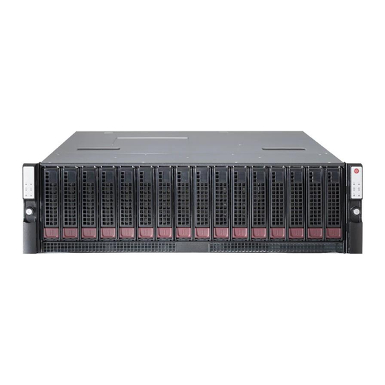
- Page 1 UPER TORAGE YSTEM 6038R-DE2CR16L USER’S MANUAL 1.0a...
- Page 2 This product, including software and docu- This manual is written for professional system integrators and PC technicians. It mentation, is the property of Supermicro and/or its licensors, and is supplied only under a license. provides information for the installation and use of the 6038R-DE2CR16L. Instal- Any use or reproduction of this product is not allowed, except as expressly permitted by the terms of said license.
- Page 3 Preface UPER TORAGE YSTEM 6038R-DE2CR16L User's Manual Notes Chapter 5: Advanced Serverboard Setup Chapter 5 provides detailed information on the X10DRS serverboard, including the locations and functions of connections, headers and jumpers. Refer to this chapter when adding or removing processors or main memory and when reconfiguring the serverboard.
-
Page 4: Table Of Contents
Table of Contents UPER TORAGE YSTEM 6038R-DE2CR16L User's Manual Table of Contents Chapter 3 System Interface Overview ......................3-1 Control Panel Button ..................3-1 Chapter 1 Introduction Power ......................3-1 Overview ......................1-1 Control Panel LEDs ..................3-1 Serverboard Features ..................1-2 Power Fail ....................... - Page 5 Table of Contents UPER TORAGE YSTEM 6038R-DE2CR16L User's Manual Installing Memory .................... 5-7 IPMI ....................... 7-34 Memory Support ....................5-7 Security Settings ................... 7-36 DIMM Installation .................... 5-7 Boot Settings ....................7-39 Installing PCI Add-On Cards ................5-9 Save & Exit ....................7-41 Serverboard Details ..................
-
Page 6: Super Storages System 6038R-De2Cr16L User's Manual
UPER TORAGE YSTEM 6038R-DE2CR16L User's Manual Notes... -
Page 7: Overview
Chapter 1 Introduction Overview The 6038R-DE2CR16L is a high-end Super Storage Bridge Bay (SBB) system comprised of two main subsystems: the SC937ETS-R1200NDBP chassis and two X10DRS dual processor serverboards. Please refer to our website for informa- tion on operating systems that have been certified for use with the system (www. -
Page 8: Serverboard Features
An IR mode SAS controller is located on a mezzanine card included in each of the Two control panels are included on each end of the 6038R-DE2CR16L to provide server nodes. One 40-port SAS expander is integrated into each X10DRS board. -
Page 9: Contacting Supermicro
Chapter 1: Introduction UPER TORAGE YSTEM 6038R-DE2CR16L User's Manual Contacting Supermicro Headquarters Figure 1-1. Intel C602J Chipset: Address: Super Micro Computer, Inc. System Block Diagram 980 Rock Ave. Note: This is a general block diagram and may not exactly represent the features San Jose, CA 95131 U.S.A. -
Page 10: Sbb: Storage Bridge Bay
YSTEM 6038R-DE2CR16L User's Manual SBB: Storage Bridge Bay The 6038R-DE2CR16L Super SBB was designed to function as a fully redundant, fault-tolerant "cluster-in-a-box" system. The standard support for 16 3.5" hot-swap HDDs (SAS2 or SAS3) may be expanded to support additional storage with the optional SBB JBOD SSG-937R-E2CJB configuration. -
Page 11: Chapter 2 Server Installation
Unpacking the System You should inspect the box the 6038R-DE2CR16L was shipped in and note if it was damaged in any way. If the server itself shows damage you should file a damage claim with the carrier who delivered it. -
Page 12: Warnings And Precautions
Chapter 2: Server Installation UPER TORAGE YSTEM 6038R-DE2CR16L User's Manual • Rack Mounting Considerations This product is for installation only in a Restricted Access Location (dedicated equipment rooms, service closets and the like). Ambient Operating Temperature • This product is not suitable for use with visual display work place devices If installed in a closed or multi-unit rack assembly, the ambient operating tempera- acccording to §2 of the the German Ordinance for Work with Visual Display Units. -
Page 13: Installing The System Into A Rack
Chapter 2: Server Installation UPER TORAGE YSTEM 6038R-DE2CR16L User's Manual Installing the System into a Rack Installing the Outer Rack Rails Outer rails attach to the server rack and hold the server in place. The outer rails for This section provides information on installing the SC937 chassis into a rack unit the SC937 chassis extend between 30 inches and 33 inches. -
Page 14: Installing The Chassis Into A Rack
UPER TORAGE YSTEM 6038R-DE2CR16L User's Manual Figure 2-3. Installing the Chassis into the Rack Installing the Chassis into a Rack Installing into a Rack 1. Confirm that the inner and outer rails are properly installed. 2. Line up the inner (chassis) rails with the front of the outer (rack) rails. -
Page 15: Chapter 3 System Interface
Chapter 3: System Interface Chapter 3 System Interface Overview There are several LEDs on two control panels as well as others on the drive carriers to keep you constantly informed of the overall status of the system as well as the activity and health of specific components. -
Page 16: Overheat/Fan Fail
6 for instructions on replacing failed drives. If this LED flashes ~ once per second (1 Hz) it indicates RAID rebuilding activity. NIC2 Indicates network activity on the LAN2 port when flashing. Heartbeat On the 6038R-DE2CR16L, this is a serverboard heartbeat LED and indicates that power is being supplied to the serverboard. - Page 17 UPER TORAGE YSTEM 6038R-DE2CR16L User's Manual Notes...
-
Page 18: Chapter 4 Standardized Warning Statements For Ac Systems
Only certified technicians should attempt to install or configure components. Read this appendix in its entirety before installing or configuring components in the Supermicro chassis. These warnings may also be found on our web site at http://www.supermicro.com/ about/policies/safety_information.cfm. Warning Definition Warning! This warning symbol means danger. - Page 19 Warning Statements for AC Systems UPER TORAGE YSTEM 6038R-DE2CR16L User's Manual Warnung جسذٌة اصابة ًتتسبب ف حالة ٌوكي أى ًاًك ف خطز ًٌٌع هذا الزهز !تحذٌز WICHTIGE SICHERHEITSHINWEISE الذوائز بالوخاطز الٌاجوة عي ي على علن ، ك هعذات تعول على أي...
-
Page 20: Installation Instructions
Chapter 4: Warning Statements for AC Systems UPER TORAGE YSTEM 6038R-DE2CR16L User's Manual Installation Instructions Circuit Breaker Warning! Warning! This product relies on the building's installation for short-circuit (overcurrent) Read the installation instructions before connecting the system to the power source. -
Page 21: Power Disconnection Warning
Chapter 4: Warning Statements for AC Systems UPER TORAGE YSTEM 6038R-DE2CR16L User's Manual ¡Advertencia! 경고! El sistema debe ser disconnected de todas las fuentes de energía y del cable 이 제품은 전원의 단락(과전류)방지에 대해서 전적으로 건물의 관련 설비에 eléctrico quitado de los módulos de fuente de alimentación antes de tener acceso 의존합니다. -
Page 22: Equipment Installation
Chapter 4: Warning Statements for AC Systems UPER TORAGE YSTEM 6038R-DE2CR16L User's Manual Equipment Installation Waarschuwing Deze apparatuur mag alleen worden geïnstalleerd, vervangen of hersteld door Warning! geschoold en gekwalificeerd personeel. Only trained and qualified personnel should be allowed to install, replace, or service Restricted Area this equipment. -
Page 23: Battery Handling
Chapter 4: Warning Statements for AC Systems UPER TORAGE YSTEM 6038R-DE2CR16L User's Manual Warnung אזור עם גישה מוגבלת Bei Einsetzen einer falschen Batterie besteht Explosionsgefahr. Ersetzen Sie die Batterie nur durch den gleichen oder vom Hersteller empfohlenen Batterietyp. !אזהרה Entsorgen Sie die benutzten Batterien nach den Anweisungen des Herstellers. -
Page 24: Redundant Power Supplies
Chapter 4: Warning Statements for AC Systems UPER TORAGE YSTEM 6038R-DE2CR16L User's Manual Redundant Power Supplies امداد الطاقة بوحدات عدة اتصاالت جهاز ال يكون لهذا قد الكهرباء عن وحدة ال لعسل كافة االتصاالت يجب إزالة 경고! Warning! This unit might have more than one power supply connection. All connections must 이... -
Page 25: Comply With Local And National Electrical Codes
Chapter 4: Warning Statements for AC Systems UPER TORAGE YSTEM 6038R-DE2CR16L User's Manual Attention מתח בפנל האחורי L'équipement doit être installé conformément aux normes électriques nationales et locales. !הרה אז קיימת סכנת מתח בפנל האחורי בזמן תפעול המערכת. יש להיזהר במהלך... -
Page 26: Hot Swap Fan Warning
Chapter 4: Warning Statements for AC Systems UPER TORAGE YSTEM 6038R-DE2CR16L User's Manual ¡Advertencia! 警告 當您從機架移除風扇裝置,風扇可能仍在轉動。小心不要將手指、螺絲起子和其他 Al deshacerse por completo de este producto debe seguir todas las leyes y 物品太靠近風扇。 reglamentos nacionales. Warnung Attention Die Lüfter drehen sich u. U. noch, wenn die Lüfterbaugruppe aus dem Chassis La mise au rebut ou le recyclage de ce produit sont généralement soumis à... -
Page 27: Power Cable And Ac Adapter
UL ou CSA câbles certifiés qui ont UL ou CSA indiqué sur le code power cables and AC adaptors. Using any other cables and adaptors could cause pour tous les autres appareils électriques que les produits désignés par Supermicro a malfunction or a fire. Electrical Appliance and Material Safety Law prohibits the seulement. -
Page 28: Presence Condition Of The Restricted Substances Marking
UPER TORAGE YSTEM 6038R-DE2CR16L User's Manual Presence Condition of the Restricted Substances Marking 限用物質含有情況標示聲明書 Declaration of the Presence Condition of the Restricted Substances Marking 937-12 設備名稱: 伺服器 ,型號(型式):SSG-6038R-DE2CR16L (系列型號: Type designation (Type) Equipment name 限用物質及其化學符號 Restricted substances and its chemical symbols 六價鉻... -
Page 29: Chapter 5 Advanced Serverboard Setup
Chapter 5: Advanced Serverboard Setup Chapter 5 Advanced Serverboard Setup This chapter provides detailed information on the X10DRS serverboard. All serverboard jumpers and connections are described. A layout and quick reference chart are also included in this chapter for your reference. Remember to completely close the chassis when you have finished working with the serverboard to better cool and protect the system. -
Page 30: Cable And Device Connectiions
IPMI. Fans can be accessed for replacement by removing the entire hot-swap server module. • Refer to the Supermicro web site for updates on CPU support. Control Panels Installing an LGA2011 Processor A ribbon cable connects each control panel to the midplane. The right and left side control panels connect to JP1 and JP2 on the midplane, respectively. - Page 31 Chapter 5: Advanced Serverboard Setup UPER TORAGE YSTEM 6038R-DE2CR16L User's Manual Warning: You can only install the CPU to the socket in one direction. Make sure that 3. With the lever labeled 'Close 1st' fully retracted, gently push down the CPU is properly inserted into the socket before closing the load plate. If it doesn't on the 'Open 1st' lever to open the close properly, do not force it as it may damage your CPU.
-
Page 32: Installing A Cpu Heatsink
Do not fully tighten the screws or you may damage the CPU.) memory. See the following tables for memory installation. For the latest memory updates, please refer to the Supermicro website. 4. Add the two remaining screws then finish the installation by fully tightening all four screws. -
Page 33: Installing Pci Add-On Cards
DIMM Module Population Configuration Memory speed support depends on the CPUs installed in your system. For the Each node in the 6038R-DE2CR16L can accommodate up to three PCI-E 3.0 x8 latest memory updates, please refer to our website at http://www.supermicro.com/ add-on cards. -
Page 34: Serverboard Details
Chapter 5: Advanced Serverboard Setup UPER TORAGE YSTEM 6038R-DE2CR16L User's Manual Serverboard Details X10DRS Quick Reference Jumper Description Default Setting Figure 5-5. X10DRS Layout JBT1 Clear CMOS See Section 5-8 (not drawn to scale) JPB1 BMC Enable/Disable Pins 1-2 (Enabled) -
Page 35: Connector And Port Definitions
Chapter 5: Advanced Serverboard Setup UPER TORAGE YSTEM 6038R-DE2CR16L User's Manual Connector and Port Definitions Fan Headers Fan Header The X10DRS has eight fan headers Pin Definitions (Fan1 - Fan8). These 4-pin fans head- Pin# Definition VGA/COM1/USB 2.0 Connector (JKVM1) -
Page 36: Jumper Settings
Chapter 5: Advanced Serverboard Setup UPER TORAGE YSTEM 6038R-DE2CR16L User's Manual Jumper Settings Watch Dog Enable/Disable Jumper JWD controls the Watch Dog function. Watch Dog is a system moni- Explanation of Jumpers tor that can reboot the system when a To modify the operation of the software application hangs. -
Page 37: Onboard Indicators
Note: For more information on SATA HostRAID configuration, please refer to the (PCH) HDD LED Intel SATA HostRAID User's Guide posted on our website at www.supermicro.com. The (PCH) HDD LED is located at HDD (PCH) HDD Activity LED LED Status LED1 on the motherboard. -
Page 38: 5-11 Installing Software
YSTEM 6038R-DE2CR16L User's Manual 5-11 Installing Software SuperDoctor® 5 The Supermicro SuperDoctor 5 is a program that functions in a command-line or The Supermicro FTP site contains drivers and utilities for your system at ftp://ftp. web-based interface in Windows and Linux operating systems. The program moni- supermicro.com. -
Page 39: 5-12 Onboard Battery
UPER TORAGE YSTEM 6038R-DE2CR16L User's Manual 5-12 Onboard Battery Please handle used batteries carefully. Do not damage the battery in any way; a damaged battery may release hazardous materials into the environment. Do not discard a used battery in the garbage or a public landfill. Please comply with the regulations set up by your local hazardous waste management agency to dispose of your used battery properly. -
Page 40: Chapter 6 Advanced Chassis Setup
Chapter 6: Advanced Chassis Setup Chapter 6 Advanced Chassis Setup This chapter covers the steps required to install components and perform mainte- nance on the SC937 chassis. For component installation, follow the steps in the order given to eliminate the most common problems encountered. If some steps are unnecessary, skip ahead to the step that follows. -
Page 41: Control Panel
Replacing System Fans Replace the failed fan with an identical 4-cm, 12-volt counter-rotating fan (p/n FAN- 0157L4, available from Supermicro). See Figures 6-2 and 6-3. Replacing Fans 1. Shutdown the node with the failed fan(s) and remove the AC power cord. -
Page 42: Drive Bay Installation/Removal
SAS drives. Proceed to the next step for instructions. Typically Large Form Factor 3.5" x 1" deep SAS drives are used. Optional conversion trays are available to install Small Form Factor 2.5" drives. Note: Refer to Supermicro's website for additional information at http://www. supermicro.com/support/manuals/. - Page 43 Drive Carrier Figure 6-6. Installing a Drive to a Carrier Release Button Warning: Enterprise level hard disk drives are recommended for use in Supermicro chassis and servers. For information on recommended HDDs, visit the Supermicro website. Warning: Regardless of how many hard drives are installed, all drive carriers must...
-
Page 44: Midplane
BC57 BC59 BC63 BC10 BC11 BC33 C106 C110 C113 C115 C117 C119 C121 C123 ment units can be ordered directly from Supermicro. The power supply units have P_M1 P_M2 P_M3 P_M7 P_M8 S_M1 S_M2 S_M3 S_M7 S_M8 P_M6 P_M13 S_M6... - Page 45 UPER TORAGE YSTEM 6038R-DE2CR16L User's Manual Notes 6-10...
-
Page 46: Chapter 7 Bios
When an option is selected in the left frame, it is highlighted in white. Often a text message will accompany it. Note: the AMI BIOS has default text messages built in. Supermicro retains the option to include, omit, or change any of these text messages. -
Page 47: How To Start The Setup Utility
Flashing the wrong BIOS can cause irreparable damage to the system. In no event shall Supermicro X10DRS-4U Supermicro be liable for direct, indirect, special, incidental, or consequential damages arising from a BIOS update. If you have to update the BIOS, do not shut down or reset BIOS Version: This item displays the version of the BIOS ROM installed in your the system while the BIOS is updating to avoid possible boot failure. -
Page 48: Advanced Setup Configurations
Chapter 7: BIOS UPER TORAGE YSTEM 6038R-DE2CR16L User's Manual Advanced Setup Configurations Wait For 'F1' If Error Select Enabled to force the system to wait until the <F1> key is pressed if an error Use the arrow keys to select Advanced setup and press <Enter> to access the occurs. - Page 49 Chapter 7: BIOS UPER TORAGE YSTEM 6038R-DE2CR16L User's Manual AC Loss Policy Depend On Hyper-Threading (All) Select BIOS for the AMI BIOS to set the AC power loss policy. Select IPMI for the Select Enable to support Intel's Hyper-threading Technology to enhance CPU per- IPMI to set the AC power loss policy.
- Page 50 Chapter 7: BIOS UPER TORAGE YSTEM 6038R-DE2CR16L User's Manual DCU IP Prefetcher Energy Performance BIAS Setting (Available when Power Technology is set to Custom or Energy Efficient) If set to Enable, the IP prefetcher in the DCU (Data Cache Unit) will prefetch IP Use this feature to select an appropriate fan setting to achieve maximum system addresses to improve network connectivity and system performance.
- Page 51 Chapter 7: BIOS UPER TORAGE YSTEM 6038R-DE2CR16L User's Manual CPU C3 Report IIO1 Configuration Select Enable to allow the BIOS to report the CPU C3 state (ACPI C2) to the IOU2 (IIO1 PCIe Port 1) operating system. During the CPU C3 state, the CPU clock generator is turned This item configures the PCI-E port Bifuraction setting for a PCI-E port specified off.
- Page 52 Chapter 7: BIOS UPER TORAGE YSTEM 6038R-DE2CR16L User's Manual Link L0p Enable be completed prior to other transactions that have already been enqueued. The options are Disable and Enable. Select Enable for Link L0p support to reduce power consumption. The options are Enable and Disable.
- Page 53 Chapter 7: BIOS UPER TORAGE YSTEM 6038R-DE2CR16L User's Manual Restore NVDIMMs Memory RAS (Reliability_Availability_Serviceability) Configuration Use this submenu to configure the following Memory RAS settings. Select Enabled for the BIOS to restore onboard NVDIMM memory support automatically to enhance memory performance. The options are Disabled RAS Mode and Enabled.
-
Page 54: Usb Configuration
Chapter 7: BIOS UPER TORAGE YSTEM 6038R-DE2CR16L User's Manual South Bridge Configuration EHCI2 Select Enabled to enable EHCI (Enhanced Host Controller Interface) support on The following South Bridge information will display: USB 2.0 connector #2 (-at least one USB 2.0 connector should be enabled for EHCI support.) The options are Disabled and Enabled. - Page 55 Chapter 7: BIOS UPER TORAGE YSTEM 6038R-DE2CR16L User's Manual sSATA Configuration sSATA Device Type Use this item to specify if the sSATA port specified by the user should be con- When this submenu is selected, AMI BIOS automatically detects the presence of nected to a Solid State drive or a Hard Disk Drive.
- Page 56 Chapter 7: BIOS UPER TORAGE YSTEM 6038R-DE2CR16L User's Manual PCIe/PCI/PnP Configuration Hot Plug PCI Latency Timer Select Enabled to enable hot-plugging support for a port specified by the user, which will allow the user to replace a SATA disk drive installed on this port without Use this item to configure the PCI latency timer for a device installed on a PCI bus.
- Page 57 Chapter 7: BIOS UPER TORAGE YSTEM 6038R-DE2CR16L User's Manual MMIO High Size IPv6 PXE Support Use this item to select the high I/O memory size according to memory-address Select Enabled to enable IPv6 PXE boot support. The options are Disabled and mapping for the PCH chip.
- Page 58 Chapter 7: BIOS UPER TORAGE YSTEM 6038R-DE2CR16L User's Manual Stop Bits Serial Port Console Redirection A stop bit indicates the end of a serial data packet. Select 1 Stop Bit for standard COM 1 Console Redirection serial data communication. Select 2 Stop Bits if slower devices are used. The options are 1 and 2.
- Page 59 Chapter 7: BIOS UPER TORAGE YSTEM 6038R-DE2CR16L User's Manual Flow Control SOL/COM2 Use this feature to set the flow control for Console Redirection to prevent data SOL/COM2 Console Redirection loss caused by buffer overflow. Send a "Stop" signal to stop sending data when Select Enabled to use the SOL port for Console Redirection.
- Page 60 Chapter 7: BIOS UPER TORAGE YSTEM 6038R-DE2CR16L User's Manual Trusting Computing *If the item above set to Enabled, the following items will become available for (Available when a TPM device is installed) user's configuration: If a TPM (Trusted Platform Module) device is detected by the BIOS, the following screen will display: EMS Console Redirection Settings (Available when EMS...
-
Page 61: Iscsi Configuration
Chapter 7: BIOS UPER TORAGE YSTEM 6038R-DE2CR16L User's Manual • ACPI Settings TPM Owner Status WHEA Support TXT Support Select Enabled to support the Windows Hardware Error Architecture (WHEA) plat- Select Enabled to enable Intel Trusted Execution Technology (TXT) support. The form and provide a common infrastructure for the system to handle hardware errors options are Disabled and Enabled. -
Page 62: Event Logs
Chapter 7: BIOS UPER TORAGE YSTEM 6038R-DE2CR16L User's Manual Event Logs When Log is Full Select Erase Immediately to immediately erase all errors in the SMBIOS event log This submenu allows the user to configure Event Log settings. when the event log is full. Select Do Nothing for the system to do nothing when the SMBIOS event log is full. - Page 63 Chapter 7: BIOS UPER TORAGE YSTEM 6038R-DE2CR16L User's Manual IPMI When SEL is Full This feature allows the user to determine what the AMI BIOS should do when the This submenu allows the user to configure Intelligent Platform Management Inter- system event log is full.
- Page 64 Chapter 7: BIOS UPER TORAGE YSTEM 6038R-DE2CR16L User's Manual Security Settings Secure Boot Select Enable for secure boot support to ensure system security at bootup. The This submenu allows the user to configure the following security settings for the options are Disabled and Enabled.
- Page 65 Chapter 7: BIOS UPER TORAGE YSTEM 6038R-DE2CR16L User's Manual Boot Settings Authorized Signatures Delete DB (DataBase) This submenu allows the user to configure Boot settings for this system: Select <Yes> to confirm deletion of a database from the NVRAM (Non-Volatile RAM).
-
Page 66: Save & Exit
Chapter 7: BIOS UPER TORAGE YSTEM 6038R-DE2CR16L User's Manual Save & Exit Boot Option #1 - Boot Option #8 Add New Boot Option This submenu allows the user to configure the following Save & Exit settings: Use this item to select a new boot device to add to the boot priority list. - Page 67 UPER TORAGE YSTEM 6038R-DE2CR16L User's Manual Save as User Defaults Select this item and press <Enter> to save the current BIOS settings as user's default settings for future use. Restore User Defaults Select this item and press <Enter> to retrieve the user-defined default settings that were previously saved to be used as current default settings.
- Page 68 Appendix A: BIOS Error Beep Codes Appendix A BIOS Error Beep Codes During the POST (Power-On Self-Test) routines, which are performed at each system boot, errors may occur. Non-fatal errors are those which, in most cases, allow the system to continue to boot.
- Page 69 UPER TORAGE YSTEM 6038R-DE2CR16L User's Manual Notes...
-
Page 70: System Specifications
Appendix B: System Specifications Appendix B System Specifications Processors (each node) Single or dual Intel® Xeon E5-2600 v3/v4 series processors in LGA 2011 R3 type sockets (both CPUs must be of the same type) Note: Please refer to our web site for a complete listing of supported processors. Chipset Intel PCH 612 BIOS... - Page 71 Appendix B: System Specifications UPER TORAGE YSTEM 6038R-DE2CR16L User's Manual Chassis California Best Management Practices Regulations for Perchlorate Materials: This Perchlorate warning applies only to products containing CR (Manganese SC937ETS-R1200NDBP (3U rackmount) Dioxide) Lithium coin cells. “Perchlorate Material-special handling may apply. See Dimensions: (WxHxD) 17.2 x 5.2 x 24.2 in.
- Page 72 YSTEM 6038R-DE2CR16L User's Manual (continued from front) The products sold by Supermicro are not intended for and will not be used in life support systems, medical equipment, nuclear facilities or systems, aircraft, aircraft devices, aircraft/emergency com- munication devices or other critical systems whose failure to perform be reasonably expected to result in significant injury or loss of life or catastrophic property damage.