Table of Contents
Advertisement
Quick Links
Applicable Country & Regions:
Europe
Product Service Manual – Level 1
Service Manual for BenQ:
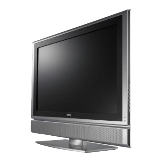
LCD TV / V37X
<9J.01B75.BAE >
Version: 001
Date:20-10-2006
Notice:
For RO to input specific "Legal Requirement" in specific NS regarding to responsibility and liability
statements.
Please check BenQ's eSupport web site, http://esupport.benq.com, to ensure that you have the most
recent version of this manual.
First Edition (August, 2006)
© Copyright BenQ Corporation 2006. All Right Reserved.
1
Advertisement
Table of Contents

Related Manuals for BenQ V37X


Summary of Contents for BenQ V37X
- Page 1 Notice: For RO to input specific “Legal Requirement” in specific NS regarding to responsibility and liability statements. Please check BenQ’s eSupport web site, http://esupport.benq.com, to ensure that you have the most recent version of this manual. First Edition (August, 2006)
-
Page 2: Table Of Contents
Content Index ABBREVIATIONS & ACRONYMS..........................3 ABOUT THIS MANUAL..............................4 INTRODUCTION ................................5 RELATED SERVICE INFORMATION ..........................7 PRODUCT OVERVIEW ..............................8 ..................................9 PECIFICATIONS .....................................59 ACKING ..............................61 USTOMER CCEPTANCE DISASSEMBLY/ASSEMBLY ............................80 ................................80 XPLODED ..............................81 ISASSEMBLY SSEMBLY LEVEL 1 COSMETIC / APPEARANCE / ALIGNMENT SERVICE...............104 & C ............................104 ISUAL NSPECTION... -
Page 3: Abbreviations & Acronyms
Abbreviations & Acronyms A/D Converter Analog to Digital Converter BenQ BenQ Corporation Digital Television Electromagnetic Interference HDMI High Definition Multimedia Interface NTSC National Television System Committee On Screen Display Phase Alternating Line RS232 Interface Between Data Terminal Equipment and Data... -
Page 4: About This Manual
About This Manual This manual contains information about maintenance and service of BenQ products. Use this manual to perform diagnostics tests, troubleshoot problems, and align the BenQ product. Important Only trained service personnel who are familiar with this BenQ Product shall perform service or maintenance to it. -
Page 5: Introduction
Introduction This section contains general service information, please read through carefully. It should be stored for easy access place. Important Service Information RoHS (2002/95/EC) Requirements – Applied to all countries require RoHS. The RoHS (Restriction of Hazardous Substance in Electrical and Electronic Equipment Directive) is a legal requirement by EU (European Union) for the global electronics industry which sold in EU and some counties also require this requirement. - Page 6 Compliance Statement Caution: This Optical Storage Product contains a Laser device. Refer to the product specifications and your local Laser Safety Compliance Requirements.
-
Page 7: Related Service Information
This Service Manual contains general information. There are 3 levels of service: Level 1: Cosmetic / Appearance / Alignment Service Level 2: Circuit Board or Standard Parts Replacement Level 3: Component Repair to Circuit Boards Related Service Information BenQ Global Service Website:http://support.benq.com/front/benqmain.asp eSupport Website:http://bqpgsr.benq.corp.com/customize/asplogin.asp... -
Page 8: Product Overview
Product Overview This specification describes a 37" diagonal LCD TV with aspect ratio of 16:9 which supports up to 1366*768 WXGA format and can display true 16.7M colors ( 8-bit/color) . This LCD TV is very thin and completely free from electromagnetic distortion. -
Page 9: Specifications
It is composed of the following material and accessories (Accessory might be adjusted by different territory request): -LCD TV *1 -User Manual + warranty card -A power cord -Remote control x 1 & AAA batteries x 2 Specifications 2.1 Environment 2.1.1 Temperature -Operating +0 to +40 degrees Celsius... - Page 10 2.2 Transportation...
- Page 12 2.3 Packaging Configuration 2.3.1 Container Specification 40’ container dimension: 11900*2280*2080(L*W*H)(in size) 20’ container dimension: 5840*2280*2080(L*W*H)(in size) 2.3.2 Product characteristics Dimension w/o Base Dimension w/ Base Net Weight (Kg) Gross Weight (Kg) W*H*D (mm) W*H*D (mm) 27.0 32.0 969.84*696.70*110.00 969.84*745.86*110.00 2.3.3 Package dimension Carton Interior Dimension (mm) Carton External Dimension (mm) W*H*D...
- Page 13 2.4 Electrostatic Discharge Requirements The subject product must withstand 8KV for contact and 15KV for air discharge of electrostatic discharge and meet the acceptance criteria as specified in BenQ ESD specification. BenQ's LCD TV Product of Reliability Design Guide Date : 25-04-2006 Rev.
- Page 14 Safety Agencies C-Tick Other CB report Agencies Class B C-Tick BenQ's LCD TV Product of Reliability Design Guide Date : 25-04-2006 Rev. 1 No Reliability BenQ (Rev.0) BenQ (Rev.1) C3 C4 C5 ORT EMI Test Test condition : Test condition: FCC part 15J class B, EN55022 class B.
- Page 15 BenQ's LCD TV Product of Reliability Design Guide Date : 25-04-2006 Rev. 1 No Reliability BenQ (Rev.0) BenQ (Rev.1) C3 C4 C5 ORT are optional. CE Marks Test condition: Directive 73/23/EEC; 1. PLT Directive 89/336/EEC 2. Voltage Dip: According to EN61000-4-11 Power Harmonic Test 3.
- Page 16 BenQ's LCD TV Product of Reliability Design Guide Date : 25-04-2006 Rev. 1 No Reliability BenQ (Rev.0) BenQ (Rev.1) C3 C4 C5 ORT 4. To measure the front side noise of the UUT, with the display is operating, fan is / 4.
- Page 17 BenQ's LCD TV Product of Reliability Design Guide Date : 25-04-2006 Rev. 1 No Reliability BenQ (Rev.0) BenQ (Rev.1) C3 C4 C5 ORT Input signal: all preset mode 2. Stress room temperature : 40± 5℃ AF : 2.541 Activation Energy(Ea) : 0.5 ev Duty cycle: 0.75...
- Page 18 BenQ's LCD TV Product of Reliability Design Guide Date : 25-04-2006 Rev. 1 No Reliability BenQ (Rev.0) BenQ (Rev.1) C3 C4 C5 ORT Criteria inspection : The performance and function shall be normality. Condensati Test condition : Same as Ver.0 on Test 1.
- Page 19 BenQ's LCD TV Product of Reliability Design Guide Date : 25-04-2006 Rev. 1 No Reliability BenQ (Rev.0) BenQ (Rev.1) C3 C4 C5 ORT highest operating temperature environment. specified lowest and highest operating temperature environment. Operating Test Condition: 0-40 ℃/10%-95% ℃/10%-90%...
- Page 20 BenQ's LCD TV Product of Reliability Design Guide Date : 25-04-2006 Rev. 1 No Reliability BenQ (Rev.0) BenQ (Rev.1) C3 C4 C5 ORT Surge Test Surge Test (EN55024:1998), EN 61000-4-5 Same as Ver.0 1KV line to line, 2KV line to ground on input power lines.
- Page 21 BenQ's LCD TV Product of Reliability Design Guide Date : 25-04-2006 Rev. 1 No Reliability BenQ (Rev.0) BenQ (Rev.1) C3 C4 C5 ORT Test Spec. : Temperature rise/fall rate : 5 ℃/ Min Temperature ℃ Step POWER Duration in Minutes ↑...
- Page 22 3. Input / Output Signal Specification Input/ Output Ports (BAE) AV1 SCART (full) (CVBS, RGB) Rear AV2 SCART (half) (CVBS, S-Video) Rear AV3(Component 1 + L/R) Rear AV4 (Composite + S-Video + L/R) Rear AV5 (Composite + S-Video + L/R) Side 1 rear, cover DVI and dedicated L/R for HDMI...
- Page 23 SIGNAL PC RED/Component Cr PC GREEN/Component Y PC BLUE/Component Cb UART_RX UART_TX RED GND GREEN GND BLUE GND PC5V SYNC GND DDC DATA (SDA) HORIZONTAL SYNC(H+V) VERTICAL SYNC DDC CLOCK (SCL) 3.1.2 Signal Level (1) PC Analog input (A)Level 0.7 volt ± 5% (B)Impedance 75 ohm.
- Page 24 (3) Video Signal Level The video signal when terminated with an idea 75ohm termination will have a range of 0V to 0.7V (normal), and its full scale output will be 0.7V and black level will be between 0V and 0.1V. 3.1.5 Signal Timing (1) PC synchronization : (A)Horizontal frequency range: 31 to 60KHz...
- Page 25 3.1.6 PC signal support timing Horizontal Vertical Dot Clock Resolution Remark Frequency(Khz) Frequency(Hz) Frequency(Mhz) 720×400 31.469 70.08 28.322 DOS, VESA 640×480 31.469 59.94 25.175 DOS, VESA 640x480 35.00 67.00 30.24 Mac.(SOG) 640×480 37.5 75.00 31.50 VESA 640x480 37.86 72.81 31.50 VESA 800x600 35.16...
- Page 26 SCART Video Signal : 3.2.1 AV1 SCART pin define & signal level: This 21 pin input/output connector confirms to “ Cenelec Scart “ specification. SCART 1 ( CVBS,S-video) SIGNAL Signal Level Impedance Tuner Audio Output Right 0.5 Vrms <1K Ohm Audio Input Right 0.5 Vrms >10K Ohm...
- Page 27 (sync input for RGB mode) Common Ground (1) Pin 20 video output : Tuner video from the last selected program. (2) Pin 1&3 audio output : Tuner audio from the last selected program. 3.2.2 Signal support timing Lines per frame Horizontal frequency(KHz) Vertical frequency(Hz) System...
- Page 28 When the RGB insertion is requested only with fast blanking (no slow switching), the synchronization is internal. The external device has to synchronize the inserted RGB with the video signal provided by the TV set at the scart output. (2) FAST BLANKING DETECTION The RGB insertion from fast blanking is per default enabled when the set is in TV, AV1 or AV2 mode.
- Page 29 AV2 Scart/ S-Video AV2 Scart/ S-Video Tuner(RF) Tuner(RF) AV3 S-Video AV3 S-Video Tuner(RF) AV3(S-Video recombined as CVBS) Component Component Tuner(RF) Tuner(RF) Tuner(RF) Tuner(RF) 3.2.7 AV2 SCART pin define & signal level : This 21 pin input/output connector confirms to the "Cenelec Scart" specification. SCART 2 ( CVBS, S-Video) SIGNAL Signal Level...
- Page 30 Video Ground CVBS output 75 Ohm- Luminance/CVBS Video Input 75 Ohm Common Ground (3) Pin 20 video output : CVBS or S-video ‘s luminance (4) Pin 1&3 audio output pin19 CVBS output : in AV2, component, PC should be tuner, in AV3/AV3 S-video is CVBS.
- Page 31 3.3 CVBS & S-Video Video Signal : 3.3.1 Connecter Pin definition : (1) S-Video pin define 4-pin S-VIDEO female SIGNAL LUMA CHROMA (2) CVBS pin define : (1) Audio Input, right channel, for CVBS and S-Video (2) Audio Input, left channel, for CVBS and S-Video (3) CVBS Video Input 3.3.2 Signal Level (1) S-Video input:...
- Page 32 Level 500mVrms Impedance > 10kΩ 3.3.3 Signal support timing Lines per frame Horizontal frequency(KHz) Vertical frequency(Hz) System 15.625 PAL(B,G,H,D,I) 15.625 SECAM 15.734 PAL-M 15.625 PAL-N 15.734 NTSC 3.3.4 Auto detected : The S-Video signal should be auto-detected if a S-Video cable is plugged (S-Video has priority over CVBS). (But in Australia Market, end users prefer to select the input source by themselves without the S-Video priority.) 3.4 RF Signal 3.4.1.
- Page 33 - NICAM DKK' 3.4.4. Color Standards: - PAL 50Hz (RF and AV-CVBS) - SECAM 50Hz (RF and AV-CVBS) - PAL 60Hz (AV-CVBS) 3.4.5. NICAM processing (1) NICAM Multilingual processing Multi-standard NICAM decoding is available. During multilingual transmissions, one of 3 mono sound channels is selectable.
- Page 34 The selected sound information values are given below: Mono Channel = (L + R)/2 (stereo forced to Mono) Sound 1 or Sound 2 [dual mono(bilingual)] Sound 1 or Sound 2 (from AV mode ) Sound 1 or Sound 2 or Sound 3 (Nicam 3) Stereo Channel = L and R (either from Two sound carrier FM stereo or from NICAM) The sound type menu setting is stored for each input (Each TV program, AV1, AV2, Component, PC).
- Page 35 automatically via VPS, PDC package extraction, or package extraction from teletext signals during manual or auto-installation. In addition, the user can manually enter the station name. If the system does not find any station name during auto-installation and if the user does not enter a name manually, the station name remains blank by default.
- Page 36 3.5 Component Video Signal : 3.5.1 Connecter Pin definition : (1) Component video pin define : (1) Cr/Pr Input (2) Cb/Pb Input (3) Y Input for YCrCb or YPrPb. (1) Component audio pin define : (1) Audio Input, right channel, for YCrCb or YprPb (2) Audio Input, left channel, for YCrCb or YPrPb 3.5.2 Signal Level (1) Level...
- Page 37 3.5.3 Signal support timing Resolution Horizontal Vertical frequency Dot Clock Remark frequency (KHz) (Hz) Frequency(Mhz) 720x480 15.735 12.27 SDTV 480i 720x480 31.25 SDTV 480p 1280x720 45.00 74.25 HDTV 720p 1280x720 37.50 74.25 HDTV 720p 1920x1080 33.75 74.25 HDTV 1080i 1920x1080 28.13 74.25 HDTV 1080i...
- Page 38 3.7 Audio monitor / Earphone output 3.7.1 Audio monitor output Signal : (1) Level 500mVrms±10% @ Input 500mVrms (2) Impedance < 1kΩ (3) 3.5mm phone plug is used for stereo audio signal output. 3.7.2 Earphone output : (1) Power L/R Max. <50mW (2) Impedance 32Ω...
- Page 39 (3.3V–300mVolts) ≤ Vicm ≤ (3.3V– Input Common Mode Voltage, Vicm 37.5mVolts) Sink AC Characteristics Item Value Minimum differential sensitivity (peak-to-peak) 150 mVolts Maximum differential input (peak-to-peak) 1560 mVolts Allowable Intra-Pair Skew at Sink Connector 0.4 Tbit Allowable Inter-Pair Skew at Sink Connector 0.6 Tpixel TMDS Clock Jitter 0.30 Tbit...
- Page 40 Item Value High voltage level (Source) Minimum 2.0 Volts, Maximum 5.3 Volts Low voltage level (Source) Minimum 0 Volts, Maximum 0.8 Volts 3.8.3 Signal support timing : Resolution Refresh Rate (Hz) Horizontal Frequency (kHz) Pixel Rate (MHz) 480i 15.75 13.51 480p 31.47 720p...
- Page 41 The user is able to adjust the tint control, when NTSC 3.58 or NTSC 4.43 has been identified. (7) Phase In component 2H and PC modes only, the user is able to adjust the Phase. The effect is to align the video transients of the source to the pixel pitch of the LCD panel, in order to offer the best possible picture.
- Page 42 (4) Inrush Current Maximum inrush current from AC power on at any point on AC Sine-wave. Must not cause any damage on the power supply. Cold Start: Less than 100 Ampere at rated input voltage at 25 ° C. (5) Regulator Efficiency 75 %min.
- Page 43 4. Output Functional specification All the tests to verify specifications in this section must be performed under the following standard conditions unless otherwise noted. The standard conditions are: -Temperature : 25 +-5 degree Celsius -AC line input voltage : 90Vac to 264Vac, 50Hz or 60Hz -Checking display mode: All the presenting modes.
- Page 44 Viewing angle by CR≥20 x axis, right (Ф =0º) x axis, left(Ф =180º) y axis, up(Ф =90º) y axis, down (Ф =270º) 1. Test conditions: (unless otherwise specified, all measurement shall be made under the test conditions below) Ambient illumination level: dark (<10 lux) Ambient temperature: 25 °C Optical test will base on standard mode and criteria follow panel Spec.
- Page 45 Normal θ Ф = 90 Ф Ф = 180 Left Ф = 0 Right Ф = 270 Down 6. Definition of Gray to Gray Switching Timing The driving signal means the signal of gray level 0, 63, 127, 191, 255. Gray to gray average time means the average switching time of gray level 0 ,63,127,191,255 to each other.
- Page 46 4.1.2. LCD Module Inspection (a) Electrical Inspection Item Acceptable count N ≦ 0 dots Bright dot Random N ≦ 0 dots 2 dots adjacent N ≦ 0 dots 3 dots adjacent or more N ≦ 7 dots Dark dots Random N ≦...
- Page 47 (c) External Appearance Inspection Criteria Item Contents Screw Parts mounting, incomplete assembly, deformation, oxidized, crooked or rusty is not permitted. CCFT cable Cable not continuous、Break-off 、 Connector Burn-off /Break-off Metal frame (Bezel) Scratch *Noticeable scratch and exfoliation coating are not permitted.
- Page 48 4.1.4. Inverter Characteristics Item UNIT Note Power Consumption IL=4.5mArms Power Supply Voltage 21.6 26.4 Power Supply Current Input Ripple Noise mVpp V =22.8V Backlight Turn 2450 Vrms Ta=0℃ Voltage 2630 Vrms Ta=25℃ Oscillating Frequency 61.5 62.5 63.5 Dimming Frequency Minimum Duty Ratio...
- Page 49 4.2 Audio Spec 4.2.1. Audio Amplifier Condition Spec Remark Input Signal Voltage 2Vpp Max. Input Sensitivity 500mVrms +/- 10% Volume Max. Max. output power L/R: 12 Wrms/ch 1KHz, 10% THD, Thermal Limit >10K Ω Input Impedance Cross Talk R/L >40dB 1W O/P <1% S/N Ratio...
- Page 50 4.3 Key pad control 1. Power key: Press this button to turn the whole system on. And press it again to turn off the system and enter standby mode. 2. Menu: Press this key to pop up the OSD menu and go back to upper level of OSD. 3.
- Page 51 4.4 OSD Control flow...
- Page 53 4.5 Remote Controller: Fig.3 Remote Controller...
- Page 54 5. Physical Specifications 5.1 Physical Dimension & Appearance 5.1.1 Overall Dimensions: ITEMS Specification 27.0 (KG) TV Set Net Weight Stand Dimension W*D 530.00 (W) * 290 (D) mm TV Set Dimension W*H*D 969.84 (W) * 745.86 (H) * 290 (D) mm Bezel Opening Size 823.17*464.47 mm TV Set Height (without Stand)
- Page 55 Fig. 3 Physical Dimension Back View and Side view 5.2 Construction and Materials on outer surface ITEMS Bezel Rear Case Stand Cover Material 65 ° C 65 ° C 65 ° C Heat Defection Temp. Flammability 94 V-0 94 V-0 94 HB Color Silver...
- Page 56 5.3.2 Controls & Connectors (1) AC power cord input: abbreviated labels (2) User's Controls: standard print 5.4 Assembly Specification ITEMS Specification Gap LCD Panel/bezel Please refer to C321 Gap front/rear cover 0.5<gap<1.5mm Gap between other plastic parts <1.0mm Step in the same plastic <0.8mm Step between different plastics <1.0mm...
- Page 57 6. Maintainability Specifications 6.1 General & Requirements 6.1.1 Installation: From outside of unit with standard tools and documentation provided to user. 6.1.2 Periodic Maintenance: No periodic maintenance is required. 6.1.3 Repair & Calibration: Require spare modules or components as specified as followings: (1) Main Board ASSY (2) Connector Board ASSY (3) Keypad Board ASSY...
- Page 58 6.4 Equipment & Tools Required 6.4.1 Standard Test Equipment (1) Power analyzer (2) Dual trace oscilloscope (3) Hand tools as required (4) Computer with IBM VGA , 8514A or compatible graphic adapter (5) Color analyzer: Minolta CA-210 or equivalent (6) Pattern Generator: Chroma 2250 or equivalent (7) TV Pattern Generator: Philips PM5418 or equivalent (8) ASTRO VG828 6.4.2 Documentation...
-
Page 59: Packing
Packing... -
Page 61: Customer Acceptance
Note: If BenQ defect undefined failure, and it judged that is reduce the merchandise ability, BenQ CM Inform this defect. - Page 62 . Visual inspection shall be down with the distance from eyes to the sample 45 cm. . Display mode: Primary mode SXGA 60Hz 11.0 TEST EQUIPMENTS 11.1 BenQ PCs with BenQ display adapter or other specific display adapter, which is agreed upon by both parties 11.2 Test program by BENQ 11.3 Power saving test tool...
- Page 63 PART I. VISUAL INSPECTION 1.0 Inspection distance for different zone: and timing to inspect Zone A: Front view of the bezel. Zone B: a) Top view and right view of the bezel. b) Front view of base stand. Zone C: Other areas can be defined as zone C. 等級區分...
- Page 64 1.1 Appearance Inspection Criteria A 級面 (A surface ) B 級面 (A surface ) C 級面 (A surface ) 規格 (Spec) 允許數 (Number of defect) 允許數 (Number of defect) 允許數 (Number of defect) 面積 cm 23”~ 27”<~ 23”<~ 27”<~ 23”<~ 27”<~ ( Area cm ≦20”...
- Page 65 刮傷(Scratch): 每個檢查面允許缺點數 目視 & 當製程無法 Defects of specified area 避免則以限度樣品 Visual Inspection, 區域 寬 / 長 > 兩不良點間允許最 Ruler & when scratch Zone Width / Length ≦10*10 cm ≦50*50 70*70cm 100*100cm 100*100cm 小距離 is unable avoid by Minimum distance make condition, then Of two points 4900 cm 10000 cm...
- Page 66 Description Class Packing 1.1 Wrong packing material Major 1.2 Carton damaged (over 6cm dia). Wet, badly taped or stapled, product will not Major arrive in good condition at customer 1.3 Carton damaged (3cm to 6cm dia), badly taped or stapled, product will arrive in Minor good condition at customer 1.4 Wrong marking of trade mark...
- Page 67 3.14 Gap between other plastic parts is over spec (refer to PS1) Major 3.15 Wiring or fixing cord comes out of cabinet or jammed Major 3.16 Auxiliary material used during production not removed Major 3.17 Cabinet parts come loose during normal handling, not safe Critical 3.18 Cabinet parts come loose during normal handling, but safe Major...
- Page 68 5.9 Wrong parts, broken component, not safe Critical 5.10 Component burn Critical PART II. OPERATIONAL INSPECTION CRITERIA 1. TEST PATTERN PATTERN TEST ITEM FULL WHITE H - Size, V - Size Light Output – Measuring the 9 points average Brightness uniformity check Impurity, dot check OFFSET, TILT FULL R, G, B, Window pattern...
- Page 69 PATTERN TEST ITEM 256/32/16 Gray Gray Check Check color temperature Including warm; cool; neutral; user General-1 pattern Performance/function check Performance/function check N-test Performance/function check TV-pattern-square Performance/function check The grid can’t be overlapped...
- Page 70 Scrat pattern- horizontal color bar Performance/function check Scart pattern-digital scan_ADC1 Performance/function check Scart pattern-vertical gray bar color bar Performance/function check Scart DVD Picture Performance/function check TV-pattern- horizontal color bar Performance/function check TV-pattern-vertical gray bar & color bar Performance/function check...
- Page 71 TV-pattern-digital scan_ADC1 Performance/function check TV and Scart function – Teletext Function check 2. Test content Test Condition TEST ITEM Input Equipment VGA480 / Gen 1 H - Size, V - Size Cross-talk Timing VESA1024 / 256 gray scale Gray scale check D-SUB Timing APPLE16 / BLUE180 MURA...
- Page 72 PAL disk Picture quality Output = PAL 4.43MHz / 50 Hz Y Cb Cr L-R balance check Sound quality Use PAL B/G system 1. Vertical color bar FM Germany stereo or FM Mono 2. Square pattern Contrast TV channel list choice 4 3.
- Page 73 3. Specification: Item Pattern Condition Specification H size Contrast: Preset 1920X1080 Brightness: Preset (819.36) V size Contrast: Preset 1920X1080 Brightness: Preset (460.89) Light Output Contrast: Max. 800 cd/m (Typical) (W/O PMMA) Brightness: Max. 550 cd/m (Typical) Brightness & Contrast: Preset Max.
- Page 74 5. OPERATIONAL INSPECTION CRITERIA: Description Class Warm up time 1.1 After switching on the product the appearance of the picture takes more than 3 Major sec. 1.2 After appearance of the picture, picture quality is not acceptable after more than 5 Major 1.3 No display Major...
- Page 75 Remote control testing distance Test condition Specification 測試項目 0˚ ± 30˚...
- Page 76 PART III INSPECTION CRITERIA 3.1 Panel electrical inspection specification: (AUO panel) Inspection Item Specification 1 Line defect Can’t be seen. 2 Random dot defect Bright dot ≦ 0 dots Dark dot ≦ 7 dots 3 Total dots defect ≦7 dots 4 Continuous defect Two continuous bright dots ≦...
- Page 77 3.2 Appearance specification 3.2.1 Judgment conditions 1) To be a distance about 45cm in front of LCD TV unit, judge the visual appearance with human’s eyes. 2) If there is any question while judging, check the panel again while operating. 3.2.2 Appearance inspection specification AUO panel Judge area...
- Page 78 3.3 Timing table 3.3.1 PC system 3.3.2 Video & S-video mode 3.3.3 Component mode...
-
Page 80: Disassembly/Assembly
Disassembly/Assembly Exploded View... -
Page 81: Disassembly / Assembly
Disassembly / Assembly Disassembly... - Page 88 Assembly...
-
Page 104: Level 1 Cosmetic / Appearance / Alignment Service
Level 1 Cosmetic / Appearance / Alignment Service Visual Inspection & Cleaning Appearance specification... -
Page 105: Adjustment / Alignment Procedure
Adjustment / Alignment Procedure 1. Preparation : (1) Setup input timing SVGA2(37.879K, 60.317Hz) & 32-Grays pattern. (2) Enter factory OSD. (3) Enter the Auto Turn on mode. (4) Power off the monitor, then power on again. (5) Setup unit and keep it warm up at least 1hour. (6) Backlight should set to “... - Page 106 3. RGB ADC Calibration : (1) Setup input timing SVGA2(38.879K, 60.317Hz) & 16-Grays pattern to DSUB connector. (2) Steup “source” to “PC”. (3) Select 16:9 format (4) Enter factory OSD (5) Enter the “ADC CAL….” page and run “Calibration” function (6) Execute “Input 16 grays scale pattern for PC”...
- Page 107 Light output standard mode (brightness=50%, contrast = 80%) Color temp item P-N/V-N @factory OSD Neutral Color 9300°K temperature 0.283±0.005 0.297±0.005 (Ymax-15%) ± 5% nits (3) Table 2 : default value of internal gain and RGB drive & offset: Intarnal gain => HAL contrast =480 Color temp item @factory OSD Neutral...
- Page 108 (1) Input source set the AV4 (CVBS) Video input. (2) set the picture to standard mode at user OSD. (3) Enter factory OSD ,select Image Processor Tuning. (4) Adjust HAL contrast to maximum, measure in this condition the maximum luminance (Ymax).
- Page 109 3. Mode => flash , options => Reset Target After Download. 4. Press "Flash" key, it appear message "Waiting for target reset". 5.Plus power line to TV ,the upgrade will operate automatically. 6.When it ok ,re-plus power line, the procedure is complete. Assembly Concerns EMI Solution Model:V37X EU Page :...
- Page 110 Stage :LP2 Doc No.: Test Engineer :Allen Jiang Test Mode: Test Date :05/09/2006 EMI Lab :QTK LAB Item Problem Solution HORIZONTAL:999MHz VERTICAL:999MHZ Add gasket between panel and main frame( Left & right) LVDS cable add clip to main frame & add...
- Page 111 foil on LVDS cord Add gasket between panel & main frame(to block a hole above shedding) HORIZONTAL:391MHz...
- Page 112 main frame paste copper to panel VERTICAL:405,648,688,702,742,891,175 195,168MHz HORIZONTAL:148,175,195MHZ...
- Page 113 add foil on keypad cord...
-
Page 114: Level 2 Circuit Board And Standard Parts Replacement
Level 2 Circuit Board and Standard Parts Replacement Block Diagram V32L- Video Block diagram... -
Page 116: Troubleshooting
Troubleshooting System trouble shooting : Power On OK? Check cable connection between AC socket and power board. Check cable connection between power board and main board. Check power board +V5S is avaluable or not Backlight OK? (No full white) Check cable connection between main board and LCD panel Remote Check remote controller battery. - Page 117 Board trouble shooting flowchart main board LED OK? Chk R702,R705,Q701,Q702 chk power +5vs OSD OK? Chk +5VS, +2.5V_PW, +3.3V_PW,+1.8V_PW UC1,Chk MODULE_ON and PWR_ON HDMI OK? Chk DPMS,+5V_DPMS,Q601 1.Chk U601 2. Chk J601 connection Component OK? Chk +9V_MSP,QC3,QC4,QC5 PC OK? Chk U501,U601 Audio OK? Check U901 Chk UA1...
- Page 118 S-Video OK? Chk U801,+9V_MSP 1.Chk Q801,Q802 2. Chk J101 CVBS OK? Chk U801,+9V_MSP 1.Chk.Q803 2.Chk J104 TV OK? Chk TV Tuner,+9V_TUNER Speaker trouble shooting flowchart 1. Check AMP_IN3, +3.3V_ST Main board 2. Check cable connection between JA1 and speaker.
-
Page 119: Level 3 - Component Repair To Curcuit Boards
Level 3 - Component Repair to Curcuit Boards Theory of Circuit Operation Main Board 2.1. Overview The Main Board includes 15 input connectors. They are HDMI input*1, component input*1, D-sub input, RF input*1, S-Video*2, Composite*2, SCART *2, Audio input (L/R)*4 and PC audio input. - Page 120 2.3 Video port input circuit 1. Video decoder PW328B: The video decoder can accept 480i, 576i, 480p, 576p, 720P and 1080i via component input connectors. It also supports NTSC M, NTSC-J SECAM and PAL via S-Video, SCART connector and composite video connector. This decoder will decode video inputs to ITU-R BT.601 digital format.
- Page 121 2.4. De-interlacer, scaler and micro-controller - PW328B The de-interlace processor accepts parallel digital ITU-R BT.601 data with H/V sync. It will convert the signal from interlace to non-interlace, format is YCBCR 4:2:2. Scaler and Micro-controller 1. The CPU was embedded on PW328B, used for controlling whole electronic boards and peripheral devices and IR receiving.
- Page 122 Scalar PW328B can process dual channel data: graphic port and video port data. It receives data with YCBCR 4:2:2 (video input) as well as RGB 4:4:4 (graphic input). 3. EEPROM The series EEPROM UD5 (AT24C128N, 128k) stores the system information, included factory and user data. 4.
- Page 123 The audio processor is used for TV tuner sound decode and controlling volume of all audio input source. The MSP 4411K family of single-chip Sound Processors covers the sound processing of PAL TV-Standards, as well as the NICAM digital sound standards and FM stereo radio. The full TV sound processing, starting with analog sound IF signal-in, down to processed analog AF-out (baseband audio), is performed on a single chip.
- Page 124 In the audio power amplifier circuit, the STA323W is an integrated solution of digital audio processing, digital amplifier control, and DDX-Power Output Stage, thereby creating a high-power single-chip DDX® solution comprising of high-quality, high-efficiency, all digital amplification. The STA323W power section consists of four independent half-bridges. Audio Amplifier Circuit...
- Page 125 6. TUNER System The Tuner is adopt PANASONIC ENG37A10GF ,the feature as bellowing: 1. +5V & +32Vinput 2. CVBS signal output 3. SIF audio output 4. I2C interface communicate 5. Support PAL-BG,I,SECAM-L,L’ system...
-
Page 126: Circuit Schematics
Circuit Schematics... -
Page 143: Pcb Artwork
PCB Artwork... -
Page 153: Appendix 1 - Screw List /Torque
Appendix 1 – Screw List /Torque... -
Page 154: Appendix 2 - Code List: Ir/Rs232
Appendix 2 – Code List: IR/RS232 IR code:... - Page 155 Customer code : 609F 00FF Power on/off 01FE 02FD 03FC Botton - 0 04FB Botton - 1 05FA Botton - 2 06F9 07F8 Botton - 4 08F7 Botton - 5 09F6 Botton - 6 0AF5 Botton - 7 0BF4 Botton - 8 13 0CF3 Botton - 9 14 0DF2 0EF1...
- Page 156 23 16E9 24 17E8 25 18E7 26 19E6 Volume + 27 1AE5 28 1BE4 29 1CE3 Left 30 1DE2 Down 1EE1 32 1FE0 33 40BF 34 41BE 35 42BD Mute 36 43BC Menu 44BB Up 38 45BA 39 46B9 40 47B8 48B7 Right 42 49B6 43 4AB5...
- Page 157 45 4CB3 46 4DB2 4EB1 48 4FB0 49 50AF 50 51AE OK 51 52AD 52 53AC 53 54AB 54 55AA 55 56A9 56 57A8 57 58A7 58 59A6 59 5AA5 60 5BA4 61 5CA3 Program + 62 5DA2 63 5EA1 64 5FA0 Botton –...
- Page 158 RS232 Code:...
- Page 162 Product System (PS) C3-328 Ass'y Drawing (Prel.) 9J.01B75.BAE Subject: Part No.: Rev.: 9J.01B75.BAE-C3-328-00 Doc. No. 9J.01B75.001 Project Code: Component Part. No.: Page 1 of 1 V37X Model Name: Marketing Description : Form No: BQY0-0B-003-32(031205)
- Page 163 Part No.: Rev.: Concerns 9J.01B75.BAE-C3-323-001 Doc. No. 9J.01B75.001 Project Code: Component Part. No.: Page 1 of 10 V37X EU VL3733 Model Name: Marketing Description : 1. Preparation : (1) Setup input timing SVGA2(37.879K, 60.317Hz) & 32-Grays pattern. (2) Enter factory OSD.
- Page 164 9J.01B75.BAE-C3-323-001 Doc. No. 9J.01B75.001 Project Code: Component Part. No.: Page 2 of 10 V37X EU VL3733 Model Name: Marketing Description : 3. RGB ADC Calibration : (1) Setup input timing SVGA2(38.879K, 60.317Hz) & 16-Grays pattern to DSUB connector. (2) Steup “source” to “PC”.
- Page 165 Part No.: Rev.: Concerns 9J.01B75.BAE-C3-323-001 Doc. No. 9J.01B75.001 Project Code: Component Part. No.: Page 3 of 10 V37X EU VL3733 Model Name: Marketing Description : Light output standard mode (brightness=50%, contrast = 80%) Color temp item P-N/V-N @factory OSD Neutral Color 9300°K...
- Page 166 Rev.: Concerns 9J.01B75.BAE-C3-323-001 Doc. No. 9J.01B75.001 Project Code: Component Part. No.: Page 4 of 10 V37X EU VL3733 Model Name: Marketing Description : (4) Table 3 : limit value of RGB drive & offset: Color temp item CVBS COMPONENT @factory OSD...
- Page 167 9J.01B75.BAE Subject: Part No.: Rev.: Concerns 9J.01B75.BAE-C3-323-001 Doc. No. 9J.01B75.001 Project Code: Component Part. No.: Page 5 of 10 V37X EU VL3733 Model Name: Marketing Description : Color R drive G drive B drive R offset G offset B offset...
- Page 168 Concerns 9J.01B75.BAE-C3-323-001 Doc. No. 9J.01B75.001 Project Code: Component Part. No.: Page 6 of 10 V37X EU VL3733 Model Name: Marketing Description : 9. software download procedure The procedure of update new software list below. download cable "RS232 <=>Dsub" 1. Use download cable to connect PC and LCDTV PC input .
- Page 169 9J.01B75.BAE Subject: Part No.: Rev.: Concerns 9J.01B75.BAE-C3-323-001 Doc. No. 9J.01B75.001 Project Code: Component Part. No.: Page 7 of 10 V37X EU VL3733 Model Name: Marketing Description : Assembly Concerns EMI Solution Model:V37X EU Page : Stage :LP2 Doc No.: Test Engineer :Allen Jiang...
- Page 170 Part No.: Rev.: Concerns 9J.01B75.BAE-C3-323-001 Doc. No. 9J.01B75.001 Project Code: Component Part. No.: Page 8 of 10 V37X EU VL3733 Model Name: Marketing Description : Add gasket between panel & main frame(to block a hole above shedding) HORIZONTAL:391MHz Form No: BQY0-0B-003-32(031205)
- Page 171 C3-323 Alignment & Assembly 9J.01B75.BAE Subject: Part No.: Rev.: Concerns 9J.01B75.BAE-C3-323-001 Doc. No. 9J.01B75.001 Project Code: Component Part. No.: Page 9 of 10 V37X EU VL3733 Model Name: Marketing Description : main frame paste copper to panel Form No: BQY0-0B-003-32(031205)
- Page 172 C3-323 Alignment & Assembly 9J.01B75.BAE Subject: Part No.: Rev.: Concerns 9J.01B75.BAE-C3-323-001 Doc. No. 9J.01B75.001 Project Code: Component Part. No.: Page 10 of 10 V37X EU VL3733 Model Name: Marketing Description : VERTICAL:405,648,688,702,742,891,175 195,168MHz HORIZONTAL:148,175,195MHZ add foil on keypad cord Form No: BQY0-0B-003-32(031205)
- Page 173 9J.01B75.BAE-C4-425-001 Doc. No. 9J.01B75.001 Project Code: Component Part. No.: Page 1 of 3 V37X EU Model Name: Marketing Description : System Trouble Shooting Flow Chart Check cable connection between AC socket and power board. Power On OK? Check cable connection between power board and main board.
- Page 174 Subject: Part No.: Rev.: 9J.01B75.BAE-C4-425-001 Doc. No. 9J.01B75.001 Project Code: Component Part. No.: Page 2 of 3 V37X EU Model Name: Marketing Description : Board trouble shooting flowchart main board Chk R702,R705,Q701,Q702 LED OK? chk power +5vs chk UC1 Chk +5VS, +2.5V_PW, +3.3V_PW,+1.8V_PW...
- Page 175 9J.01B75.BAE Subject: Part No.: Rev.: 9J.01B75.BAE-C4-425-001 Doc. No. 9J.01B75.001 Project Code: Component Part. No.: Page 3 of 3 V37X EU Model Name: Marketing Description : Chk U801,+9V_MSP 1.Chk Q801,Q802 S-Video OK? 2. Chk J101 Chk U801,+9V_MSP 1.Chk.Q803 CVBS OK? 2.Chk J104...
- Page 176 Model Name Model Name Model Name OEM/ODM Model Name OEM/ODM Model Name OEM/ODM Model Name R109 R109 L109 L109 R146 R146 V37X EU V37X EU V37X EU V37X EU V37X EU V37X EU 9J.01B75.001 9J.01B75.001 9J.01B75.001 2B13051021 2B13051021 LL4148 LL4148...
- Page 177 BenQ Corporation Project Code Project Code Project Code Model Name Model Name Model Name OEM/ODM Model Name OEM/ODM Model Name OEM/ODM Model Name V37X EU V37X EU V37X EU 9J.01B75.001 9J.01B75.001 9J.01B75.001 V37X EU V37X EU V37X EU Title Title...
- Page 178 15V 150PF Project Code Project Code Project Code Model Name Model Name Model Name OEM/ODM Model Name OEM/ODM Model Name OEM/ODM Model Name V37X EU V37X EU V37X EU 9J.01B75.001 9J.01B75.001 9J.01B75.001 V37X EU V37X EU V37X EU Title Title...
- Page 179 BC847C BC847C Project Code Project Code Project Code Model Name Model Name Model Name OEM/ODM Model Name OEM/ODM Model Name OEM/ODM Model Name V37X EU V37X EU V37X EU 9J.01B75.001 9J.01B75.001 9J.01B75.001 V37X EU V37X EU V37X EU C420 C420...
- Page 180 C509 Project Code Project Code Project Code Model Name Model Name Model Name OEM/ODM Model Name OEM/ODM Model Name OEM/ODM Model Name V37X EU V37X EU V37X EU MCU_TX H : DTV DL 9J.01B75.001 9J.01B75.001 9J.01B75.001 V37X EU V37X EU...
- Page 181 Z120 VOUT1 Project Code Project Code Project Code Model Name Model Name Model Name OEM/ODM Model Name OEM/ODM Model Name OEM/ODM Model Name V37X EU V37X EU V37X EU 9J.01B75.001 9J.01B75.001 9J.01B75.001 V37X EU V37X EU V37X EU VOUT2 C629...
- Page 182 Z600 Project Code Project Code Project Code Model Name Model Name Model Name OEM/ODM Model Name OEM/ODM Model Name OEM/ODM Model Name V37X EU V37X EU V37X EU 9J.01B75.001 9J.01B75.001 9J.01B75.001 V37X EU V37X EU V37X EU 1A 0.2OHM 1A 0.2OHM...
- Page 183 BenQ Corporation Project Code Project Code Project Code Model Name Model Name Model Name OEM/ODM Model Name OEM/ODM Model Name OEM/ODM Model Name V37X EU V37X EU V37X EU 9J.01B75.001 9J.01B75.001 9J.01B75.001 V37X EU V37X EU V37X EU Title Title...
- Page 184 MSP_RST1 Project Code Project Code Project Code Model Name Model Name Model Name OEM/ODM Model Name OEM/ODM Model Name OEM/ODM Model Name MSP_RST V37X EU V37X EU V37X EU 9J.01B75.001 9J.01B75.001 9J.01B75.001 V37X EU V37X EU V37X EU 0_DNP 0_DNP...
- Page 185 BenQ Corporation Project Code Project Code Project Code Model Name Model Name Model Name OEM/ODM Model Name OEM/ODM Model Name OEM/ODM Model Name V37X EU V37X EU V37X EU 9J.01B75.001 9J.01B75.001 9J.01B75.001 V37X EU V37X EU V37X EU Title Title...
- Page 186 Model Name OEM/ODM Model Name OEM/ODM Model Name OEM/ODM Model Name 15V 150PF 15V 150PF 15V 150PF 15V 150PF 15V 150PF 15V 150PF V37X EU V37X EU V37X EU 9J.01B75.001 9J.01B75.001 9J.01B75.001 V37X EU V37X EU V37X EU Title Title...
- Page 187 BenQ Corporation Project Code Project Code Project Code Model Name Model Name Model Name OEM/ODM Model Name OEM/ODM Model Name OEM/ODM Model Name V37X EU V37X EU V37X EU 9J.01B75.001 9J.01B75.001 9J.01B75.001 V37X EU V37X EU V37X EU Title Title...
- Page 188 Project Code Project Code Project Code Model Name Model Name Model Name OEM/ODM Model Name OEM/ODM Model Name OEM/ODM Model Name ADC4 DAC2 V37X EU V37X EU V37X EU 9J.01B75.001 9J.01B75.001 9J.01B75.001 V37X EU V37X EU V37X EU ADC5 DAC3...
- Page 189 BenQ Corporation Project Code Project Code Project Code Model Name Model Name Model Name OEM/ODM Model Name OEM/ODM Model Name OEM/ODM Model Name V37X EU V37X EU V37X EU 9J.01B75.001 9J.01B75.001 9J.01B75.001 V37X EU V37X EU V37X EU 128Mb R222 R223-->open...
- Page 190 BenQ Corporation Project Code Project Code Project Code Model Name Model Name Model Name OEM/ODM Model Name OEM/ODM Model Name OEM/ODM Model Name V37X EU V37X EU V37X EU 9J.01B75.001 9J.01B75.001 9J.01B75.001 V37X EU V37X EU V37X EU Title Title...
- Page 191 BenQ Corporation Project Code Project Code Project Code Model Name Model Name Model Name OEM/ODM Model Name OEM/ODM Model Name OEM/ODM Model Name V37X EU V37X EU V37X EU 9J.01B75.001 9J.01B75.001 9J.01B75.001 V37X EU V37X EU V37X EU Title Title...
- Page 192 2N3904S 2N3904S Project Code Project Code Project Code Model Name Model Name Model Name OEM/ODM Model Name OEM/ODM Model Name OEM/ODM Model Name V37X EU V37X EU V37X EU 9J.01B75.001 9J.01B75.001 9J.01B75.001 V37X EU V37X EU V37X EU RH14 RH14...