
Related Manuals for Nokia RM-721


Summary of Contents for Nokia RM-721
- Page 1 Nokia Customer Care Service Manual RM-721; RM-722 (Nokia C2-01) Mobile Terminal Part No: (Issue 1) COMPANY CONFIDENTIAL Copyright © 2011 Nokia. All rights reserved.
- Page 2 RM-721; RM-722 Amendment Record Sheet Amendment Record Sheet Amendment No Date Inserted By Comments Issue 1 01/2011 Jeff Zhao Page ii COMPANY CONFIDENTIAL Issue 1 Copyright © 2011 Nokia. All rights reserved.
- Page 3 Nokia operates a policy of continuous development. Nokia reserves the right to make changes and improvements to any of the products described in this document without prior notice. Under no circumstances shall Nokia be responsible for any loss of data or income or any special, incidental, consequential or indirect damages howsoever caused.
- Page 4 WCDMA networks and cause problems to 3G cellular phone communication in a wide area. • During testing never activate the GSM or WCDMA transmitter without a proper antenna load, otherwise GSM or WCDMA PA may be damaged. Page iv COMPANY CONFIDENTIAL Issue 1 Copyright © 2011 Nokia. All rights reserved.
- Page 5 Use only approved accessories and batteries. Do not connect incompatible products. CONNECTING TO OTHER DEVICES When connecting to any other device, read its user’s guide for detailed safety instructions. Do not connect incompatible products. Issue 1 COMPANY CONFIDENTIAL Page v Copyright © 2011 Nokia. All rights reserved.
- Page 6 All of the above suggestions apply equally to the product, battery, charger or any accessory. Page vi COMPANY CONFIDENTIAL Issue 1 Copyright © 2011 Nokia. All rights reserved.
- Page 7 RM-721; RM-722 ESD protection ESD protection Nokia requires that service points have sufficient ESD protection (against static electricity) when servicing the phone. Any product of which the covers are removed must be handled with ESD protection. The SIM card can be replaced without ESD protection if the product is otherwise ready for use.
- Page 8 Batteries' performance is particularly limited in temperatures well below freezing. Do not dispose of batteries in a fire! Dispose of batteries according to local regulations (e.g. recycling). Do not dispose as household waste. Page viii COMPANY CONFIDENTIAL Issue 1 Copyright © 2011 Nokia. All rights reserved.
- Page 9 Our policy is of continuous development; details of all technical modifications will be included with service bulletins. While every endeavour has been made to ensure the accuracy of this document, some errors may exist. If any errors are found by the reader, NOKIA MOBILE PHONES Business Group should be notified in writing/e- mail. Please state: •...
- Page 10 RM-721; RM-722 Company policy (This page left intentionally blank.) Page x COMPANY CONFIDENTIAL Issue 1 Copyright © 2011 Nokia. All rights reserved.
- Page 11 Nokia C2-01 Service Manual Structure 1 General information 2 Service Devices and Service Concepts 3 BB Troubleshooting and Manual Tuning Guide 4 RF Troubleshooting 5 System Module Glossary Issue 1 COMPANY CONFIDENTIAL Page xi Copyright © 2011 Nokia. All rights reserved.
- Page 12 RM-721; RM-722 Nokia C2-01 Service Manual Structure (This page left intentionally blank.) Page xii COMPANY CONFIDENTIAL Issue 1 Copyright © 2011 Nokia. All rights reserved.
- Page 13 Nokia Customer Care 1 — General information Issue 1 COMPANY CONFIDENTIAL Page 1 – 1 Copyright © 2011 Nokia. All rights reserved.
- Page 14 RM-721; RM-722 General information (This page left intentionally blank.) Page 1 – 2 COMPANY CONFIDENTIAL Issue 1 Copyright © 2011 Nokia. All rights reserved.
-
Page 15: Table Of Contents
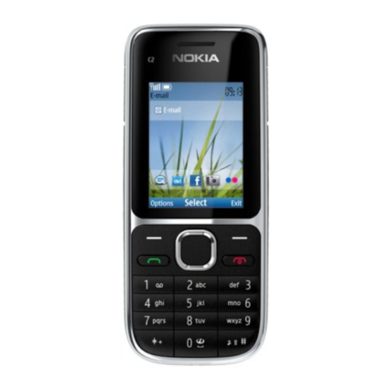
1–9 Table 4 Music ................................. 1–9 Table 5 Navigation ..............................1–9 Table 6 Power ................................ 1–9 List of Figures Figure 1 RM-721/RM-722 product picture......................1–5 Issue 1 COMPANY CONFIDENTIAL Page 1 – 3 Copyright © 2011 Nokia. All rights reserved. - Page 16 RM-721; RM-722 General information (This page left intentionally blank.) Page 1 – 4 COMPANY CONFIDENTIAL Issue 1 Copyright © 2011 Nokia. All rights reserved.
-
Page 17: Product Selection
RM-721; RM-722 General information Product selection RM-721/RM-722 is a WCDMA/GSM handportable phone with a slide form factor. RM-722 supports EGSM 850/900/1800/1900 and WCDMA 850/1900/2100. RM-721 supports EGSM 850/900/1800/1900 and WCDMA 900/1900/2100 bands. The device supports GPRS/EGPRS and WCDMA data bearers. - Page 18 • NMS 2.0 Nokia IM client • Facebook client • MySpace client • WAP 2.0 • Java MIDP 2.1 • Applications: Calculator 2, Converter 2, Size converter, Mobile Search Client (Nokia Search v. 2.0) tbd., MyNokia Page 1 – 6 COMPANY CONFIDENTIAL Issue 1...
-
Page 19: Product And Module List
RM-721; RM-722 General information • Nokia Life Tools 1.6 and V1.7 in later release • Flickr Image Upload (pre loaded link) • Music player (Media player) • Nokia Maps enabling (v. 2.0 )supported • Games (e.g. Bounce II, Brain Champion, SudokuII, Block’d, Tower City Bloxx, Diamond rush) •... -
Page 20: Mobile Enhancements
BH-504 BH-606 BH-701 BH-703 BH-804 BH-904 Wireless loopset LPS-5 Table 2 Car Enhancement Type Auto Navigation Nokia 500 Auto Navigation Car kit CK-7Wi CK-100 CK-300 Page 1 – 8 COMPANY CONFIDENTIAL Issue 1 Copyright © 2011 Nokia. All rights reserved. -
Page 21: Table 3 Data
Table 5 Navigation Enhancement Type Wireless GPS Module LD-3W LD-4W Table 6 Power Enhancement Type Battery 1020 mAh Li-Ion BL-5C Back-up power DC-11 First aid charger DC-8 Issue 1 COMPANY CONFIDENTIAL Page 1 – 9 Copyright © 2011 Nokia. All rights reserved. -
Page 22: Technical Specifications
Main RF characteristics for GSM 850/900/1800/1900, WCDMA 900/1900/2100 and WCDMA 850/1900/2100 phones Parameter Unit Cellular system GSM850, EGSM900, GSM1800/1900, WCDMA V (850), WCDMA VIII (900), WCDMA II (1900) and WCDMA I (2100) Page 1 – 10 COMPANY CONFIDENTIAL Issue 1 Copyright © 2011 Nokia. All rights reserved. - Page 23 WCDMA I (2100): 1920 - 1980 MHz Output power GSM850: +5...32.5dBm/3.2mW...1.8W GSM900: +5...32.5dBm/3.2mW...1.8W GSM1800: +0...29.5dBm/1mW...0.9W GSM1900: +0...29.5dBm/1mW...0.9W WCDMA VIII (900) [RM-721 only]: -50...+23dBm/ 0.01µW...200mW WCDMA V (850) [RM-722 only]: -50...+23dBm/ 0.01µW...200mW WCDMA II (1900): -50...+23dBm/0.01µW...200mW WCDMA I (2100): -50...+23dBm/0.01µW...200mW EDGE output power EDGE850: +5...26.5dBm/3.2mW...447mW...
-
Page 24: Environmental Conditions
No storage or operation: an <-40 C...>+85 attempt may damage the phone. Charging allowed C...+50 Long term storage conditions C...+85 Humidity Relative humidity range is 5...95%. Page 1 – 12 COMPANY CONFIDENTIAL Issue 1 Copyright © 2011 Nokia. All rights reserved. - Page 25 The standard for electrostatic discharge is IEC 61000-4-2, and this device fulfils level 4 requirements. RoHS This device uses RoHS compliant components and lead-free soldering process. Issue 1 COMPANY CONFIDENTIAL Page 1 – 13 Copyright © 2011 Nokia. All rights reserved.
- Page 26 RM-721; RM-722 General information (This page left intentionally blank.) Page 1 – 14 COMPANY CONFIDENTIAL Issue 1 Copyright © 2011 Nokia. All rights reserved.
- Page 27 Nokia Customer Care 2 — Service Devices and Service Concepts Issue 1 COMPANY CONFIDENTIAL Page 2 – 1 Copyright © 2011 Nokia. All rights reserved.
- Page 28 RM-721; RM-722 Service Devices and Service Concepts (This page left intentionally blank.) Page 2 – 2 COMPANY CONFIDENTIAL Issue 1 Copyright © 2011 Nokia. All rights reserved.
-
Page 29: Table Of Contents
2–16 Figure 7 Service concept for RF testing and RF/BB tuning ................2–17 Figure 8 Service concept for RF testing and RF/BB tuning ................2–18 Issue 1 COMPANY CONFIDENTIAL Page 2 – 3 Copyright © 2011 Nokia. All rights reserved. - Page 30 RM-721; RM-722 Service Devices and Service Concepts (This page left intentionally blank.) Page 2 – 4 COMPANY CONFIDENTIAL Issue 1 Copyright © 2011 Nokia. All rights reserved.
-
Page 31: Service Devices
The table below gives a short overview of service devices that can be used for testing, error analysis, and repair of product RM-721; RM-722. For the correct use of the service devices, and the best effort of workbench setup, please refer to various concepts. - Page 32 4 Connect an FBUS cable (if necessary). 5 Start Phoenix service software. Note: Phoenix enables CU-4 regulators via USB when it is started. Reconnecting the power supply requires a Phoenix restart. Page 2 – 6 COMPANY CONFIDENTIAL Issue 1 Copyright © 2011 Nokia. All rights reserved.
-
Page 33: Fps-21
In order to access the SD memory card slots inside FPS-21, the prommer needs to be opened by removing the front panel, rear panel and heatsink from the prommer body. Issue 1 COMPANY CONFIDENTIAL Page 2 – 7 Copyright © 2011 Nokia. All rights reserved. - Page 34 • Installation and warranty information SRT-6 Opening tool SRT-6 is used to open phone covers. Note: The SRT-6 is included in the Nokia Standard Toolkit. SS-46 Interface adapter SS-46 acts as an interface adapter between the flash adapter and FPS-21.
-
Page 35: Cables
The table below gives a short overview of service devices that can be used for testing, error analysis, and repair of product RM-721; RM-722. For the correct use of the service devices, and the best effort of workbench setup, please refer to various concepts. -
Page 36: Ca-158Rs
The CA-31D USB cable is used to connect FPS-21 to a PC. It is included in the FPS-21 sales package. CA-89DS Cable Provides VBAT and Flashbus connections to mobile device programming adapters. Page 2 – 10 COMPANY CONFIDENTIAL Issue 1 Copyright © 2011 Nokia. All rights reserved. -
Page 37: Dau-9S
The RF cable is used to connect, for example, a module repair jig to the RF measurement equipment. SMA to N-Connector approximately 610 mm. Attenuation for: • GSM850/900: 0.3+-0.1 dB • GSM1800/1900: 0.5+-0.1 dB • WLAN: 0.6+-0.1dB Issue 1 COMPANY CONFIDENTIAL Page 2 – 11 Copyright © 2011 Nokia. All rights reserved. -
Page 38: Service Concepts
Figure 2 POS flash concept Type Description Product specific tools BL-5C Battery Other tools FLS-5 POS flash dongle PC with service software Cables CA-101 Micro USB cable Page 2 – 12 COMPANY CONFIDENTIAL Issue 1 Copyright © 2011 Nokia. All rights reserved. -
Page 39: Pos (Point Of Sale) Flash Concept - Option 2
RM-721; RM-722 Service Devices and Service Concepts POS (Point of Sale) flash concept — option 2 Figure 3 POS flash concept — option 2 Issue 1 COMPANY CONFIDENTIAL Page 2 – 13 Copyright © 2011 Nokia. All rights reserved. -
Page 40: Flash Concept With Fps-21
FPS-21 Flash prommer box AC-35 Power supply PK-1 SW security device SS-46 Interface adapter PC with Phoenix service software Cables CA-89DS Service cable USB cable Page 2 – 14 COMPANY CONFIDENTIAL Issue 1 Copyright © 2011 Nokia. All rights reserved. -
Page 41: Flash Concept With Fps-21
Flash adapter base SX-4 Smart card (for DCT-4 generation mobile device programming) PC with Phoenix service software Cables PCS-1 Power cable CA-89DS Service cable Standard USB cable Issue 1 COMPANY CONFIDENTIAL Page 2 – 15 Copyright © 2011 Nokia. All rights reserved. -
Page 42: Module Jig Service Concept
SX-4 Smart card PC with VPOS and Phoenix service software Measurement equipment Cables CA-89DS Service cable PCS-1 DC power cable XRS-6 RF cable USB cable Page 2 – 16 COMPANY CONFIDENTIAL Issue 1 Copyright © 2011 Nokia. All rights reserved. -
Page 43: Service Concept For Rf Testing And Rf/Bb Tuning
PK-1 SW security device SX-4 Smart card Measurement equipment Smart card reader PC with Phoenix service software Cables DAU-9S MBUS cable PCS-1 DC power cable Issue 1 COMPANY CONFIDENTIAL Page 2 – 17 Copyright © 2011 Nokia. All rights reserved. -
Page 44: Bluetooth Testing Concept With
PK-1 SW security device SX-4 Smart card SB-6 Bluetooth test and interface box Smart card reader PC with Phoenix service software Cables DAU-9S MBUS cable Page 2 – 18 COMPANY CONFIDENTIAL Issue 1 Copyright © 2011 Nokia. All rights reserved. - Page 45 RM-721; RM-722 Service Devices and Service Concepts Type Description PCS-1 DC power cable USB cable Issue 1 COMPANY CONFIDENTIAL Page 2 – 19 Copyright © 2011 Nokia. All rights reserved.
- Page 46 RM-721; RM-722 Service Devices and Service Concepts (This page left intentionally blank.) Page 2 – 20 COMPANY CONFIDENTIAL Issue 1 Copyright © 2011 Nokia. All rights reserved.
- Page 47 Nokia Customer Care 3 — BB Troubleshooting and Manual Tuning Guide Issue 1 COMPANY CONFIDENTIAL Page 3 – 1 Copyright © 2011 Nokia. All rights reserved.
- Page 48 RM-721; RM-722 BB Troubleshooting and Manual Tuning Guide (This page left intentionally blank.) Page 3 – 2 COMPANY CONFIDENTIAL Issue 1 Copyright © 2011 Nokia. All rights reserved.
-
Page 49: Table 6 Power
..........................3–51 Product code change DCT-4.......................... 3–53 Use of SX-4T smart card in product code change..................3–55 Flash pin for DCT-4 ............................3–56 Troubleshooting............................3–58 Issue 1 COMPANY CONFIDENTIAL Page 3 – 3 Copyright © 2011 Nokia. All rights reserved. - Page 50 Figure 11 Differential output waveform of the Ext_in_IHF_out out loop measurement when speaker is connected..............................3–32 Figure 12 Single-ended output waveform of the HP_in_Ext_out loop when microphone is connected. 3–33 Page 3 – 4 COMPANY CONFIDENTIAL Issue 1 Copyright © 2011 Nokia. All rights reserved.
-
Page 51: Baseband Self Tests In Phoenix
Always start the troubleshooting procedure by running the Phoenix self tests. If a test fails, please follow the diagram below. Dead or jammed device troubleshooting. If the phone is dead and you cannot perform the self tests, go to Issue 1 COMPANY CONFIDENTIAL Page 3 – 5 Copyright © 2011 Nokia. All rights reserved. - Page 52 RM-721; RM-722 BB Troubleshooting and Manual Tuning Guide Troubleshooting flow Page 3 – 6 COMPANY CONFIDENTIAL Issue 1 Copyright © 2011 Nokia. All rights reserved.
-
Page 53: Power And Charging Troubleshooting
RM-721; RM-722 BB Troubleshooting and Manual Tuning Guide Power and charging troubleshooting Dead or jammed device troubleshooting Troubleshooting flow - Page 1 of 2 Issue 1 COMPANY CONFIDENTIAL Page 3 – 7 Copyright © 2011 Nokia. All rights reserved. - Page 54 RM-721; RM-722 BB Troubleshooting and Manual Tuning Guide Troubleshooting flow - Page 2 of 2 Page 3 – 8 COMPANY CONFIDENTIAL Issue 1 Copyright © 2011 Nokia. All rights reserved.
-
Page 55: Power Key (End Key) Troubleshooting
RM-721; RM-722 BB Troubleshooting and Manual Tuning Guide Power key (End key) troubleshooting Troubleshooting flow Issue 1 COMPANY CONFIDENTIAL Page 3 – 9 Copyright © 2011 Nokia. All rights reserved. -
Page 56: General Voltage Checking Troubleshooting
RM-721; RM-722 BB Troubleshooting and Manual Tuning Guide General voltage checking troubleshooting Troubleshooting flow - Page 1 of 2 Page 3 – 10 COMPANY CONFIDENTIAL Issue 1 Copyright © 2011 Nokia. All rights reserved. - Page 57 RM-721; RM-722 BB Troubleshooting and Manual Tuning Guide Troubleshooting flow - Page 2 of 2 Issue 1 COMPANY CONFIDENTIAL Page 3 – 11 Copyright © 2011 Nokia. All rights reserved.
-
Page 58: General Power Checking
Pearl_J 1.8/3.0 SIM card VAUX1 Pearl_J 2.5/2.8 Camera, display and hall sensor VANA (VAUX1) Pearl_J Camera Pearl_J Crystal oscillators VMEM Pearl_J microSD Disabled in sleep Page 3 – 12 COMPANY CONFIDENTIAL Issue 1 Copyright © 2011 Nokia. All rights reserved. -
Page 59: Charging Troubleshooting
RM-721; RM-722 BB Troubleshooting and Manual Tuning Guide Charging troubleshooting Troubleshooting flow Issue 1 COMPANY CONFIDENTIAL Page 3 – 13 Copyright © 2011 Nokia. All rights reserved. -
Page 60: Usb Charging Troubleshooting
RM-721; RM-722 BB Troubleshooting and Manual Tuning Guide USB charging troubleshooting Troubleshooting flow Page 3 – 14 COMPANY CONFIDENTIAL Issue 1 Copyright © 2011 Nokia. All rights reserved. -
Page 61: Battery Current Measuring Fault Troubleshooting
RM-721; RM-722 BB Troubleshooting and Manual Tuning Guide Battery current measuring fault troubleshooting Troubleshooting flow Issue 1 COMPANY CONFIDENTIAL Page 3 – 15 Copyright © 2011 Nokia. All rights reserved. -
Page 62: Interface Troubleshooting
RM-721; RM-722 BB Troubleshooting and Manual Tuning Guide Interface troubleshooting Flash programming fault troubleshooting Troubleshooting flow - Page 1 of 2 Page 3 – 16 COMPANY CONFIDENTIAL Issue 1 Copyright © 2011 Nokia. All rights reserved. - Page 63 BB Troubleshooting and Manual Tuning Guide Troubleshooting flow - Page 2 of 2 Figure 9 Flashing pic 1. Take single trig measurement for the rise of the BSI signal Issue 1 COMPANY CONFIDENTIAL Page 3 – 17 Copyright © 2011 Nokia. All rights reserved.
-
Page 64: Sim Card Troubleshooting
RM-721; RM-722 BB Troubleshooting and Manual Tuning Guide SIM card troubleshooting Troubleshooting flow Page 3 – 18 COMPANY CONFIDENTIAL Issue 1 Copyright © 2011 Nokia. All rights reserved. - Page 65 RM-721; RM-722 BB Troubleshooting and Manual Tuning Guide Issue 1 COMPANY CONFIDENTIAL Page 3 – 19 Copyright © 2011 Nokia. All rights reserved.
-
Page 66: Microsd Card Troubleshooting
RM-721; RM-722 BB Troubleshooting and Manual Tuning Guide MicroSD card troubleshooting Troubleshooting flow Page 3 – 20 COMPANY CONFIDENTIAL Issue 1 Copyright © 2011 Nokia. All rights reserved. -
Page 67: Usb Data Interface Troubleshooting
RM-721; RM-722 BB Troubleshooting and Manual Tuning Guide USB data interface troubleshooting Troubleshooting flow - Page 1 of 2 Issue 1 COMPANY CONFIDENTIAL Page 3 – 21 Copyright © 2011 Nokia. All rights reserved. -
Page 68: User Interface Troubleshooting
If one or more keys are stuck, so that the key does not react when a keydome key is pressed, the failure is caused by mechanical reasons (dirt, rust, mechanical damage, etc.) If the failure mode is not clear, start with the Keyboard test in Phoenix. Page 3 – 22 COMPANY CONFIDENTIAL Issue 1 Copyright © 2011 Nokia. All rights reserved. - Page 69 RM-721; RM-722 BB Troubleshooting and Manual Tuning Guide Troubleshooting flow Issue 1 COMPANY CONFIDENTIAL Page 3 – 23 Copyright © 2011 Nokia. All rights reserved.
-
Page 70: Numerical Keypad Illumination Troubleshooting
• The display is in a normal mode when the phone is in active use. • Display is in a sleep mode when the phone is in the screen saver mode. Page 3 – 24 COMPANY CONFIDENTIAL Issue 1 Copyright © 2011 Nokia. All rights reserved. - Page 71 APE ID). 3. Proceed to the display troubleshooting flowcharts. Phoenix to find the detailed fault mode. Use the Display Test tool in Issue 1 COMPANY CONFIDENTIAL Page 3 – 25 Copyright © 2011 Nokia. All rights reserved.
-
Page 72: Display Module Troubleshooting
BB Troubleshooting and Manual Tuning Guide Display module troubleshooting Context Use the display test tool in Phoenix to find the detailed fault mode. Troubleshooting flow Page 3 – 26 COMPANY CONFIDENTIAL Issue 1 Copyright © 2011 Nokia. All rights reserved. -
Page 73: Bluetooth And Fm Radio Troubleshooting
RM-721; RM-722 BB Troubleshooting and Manual Tuning Guide Bluetooth and FM radio troubleshooting Bluetooth troubleshooting Troubleshooting flow Issue 1 COMPANY CONFIDENTIAL Page 3 – 27 Copyright © 2011 Nokia. All rights reserved. -
Page 74: Fm Radio Troubleshooting
Taking and evaluating test pictures with main camera taking a test picture, remember the following: When • Avoid bright fluorescent light, 50/60Hz electrical network or high artificial illumination levels Page 3 – 28 COMPANY CONFIDENTIAL Issue 1 Copyright © 2011 Nokia. All rights reserved. -
Page 75: Camera Troubleshooting
• Analyse the picture from your PC monitor, full colour setting is recommended • If possible, compare with a picture of the same motive taken with a similar Nokia device • If camera has auto focus: Remember that the white focussing frame which appears when the camera button is pressed halfway down, must turn green for auto focus lock. -
Page 76: Camera Hardware Troubleshooting
The input signal for each loop test can be either single-ended or differential. Required equipment The following equipment is needed for the tests: • Oscilloscope Page 3 – 30 COMPANY CONFIDENTIAL Issue 1 Copyright © 2011 Nokia. All rights reserved. - Page 77 XMICP and EarP and GND 10.9 Mic to EarN and GND Internal Earpiece External XMICP and IHF pads 28.1 2540 112mA Mic to (calc.) Internal handsfree Issue 1 COMPANY CONFIDENTIAL Page 3 – 31 Copyright © 2011 Nokia. All rights reserved.
- Page 78 2kHz. Figure 11 Differential output waveform of the Ext_in_IHF_out out loop measurement when speaker is connected. Page 3 – 32 COMPANY CONFIDENTIAL Issue 1 Copyright © 2011 Nokia. All rights reserved.
-
Page 79: Internal Earpiece Troubleshooting
RM-721; RM-722 BB Troubleshooting and Manual Tuning Guide Figure 12 Single-ended output waveform of the HP_in_Ext_out loop when microphone is connected. Internal earpiece troubleshooting Troubleshooting flow Issue 1 COMPANY CONFIDENTIAL Page 3 – 33 Copyright © 2011 Nokia. All rights reserved. -
Page 80: Internal Microphone Troubleshooting
RM-721; RM-722 BB Troubleshooting and Manual Tuning Guide Internal microphone troubleshooting Troubleshooting flow Page 3 – 34 COMPANY CONFIDENTIAL Issue 1 Copyright © 2011 Nokia. All rights reserved. -
Page 81: Internal Handsfree (Ihf) Troubleshooting
RM-721; RM-722 BB Troubleshooting and Manual Tuning Guide Internal handsfree (IHF) troubleshooting Troubleshooting flow Issue 1 COMPANY CONFIDENTIAL Page 3 – 35 Copyright © 2011 Nokia. All rights reserved. -
Page 82: External Earpiece Troubleshooting
RM-721; RM-722 BB Troubleshooting and Manual Tuning Guide External earpiece troubleshooting Troubleshooting flow Page 3 – 36 COMPANY CONFIDENTIAL Issue 1 Copyright © 2011 Nokia. All rights reserved. -
Page 83: External Microphone Troubleshooting
RM-721; RM-722 BB Troubleshooting and Manual Tuning Guide External microphone troubleshooting Troubleshooting flow Issue 1 COMPANY CONFIDENTIAL Page 3 – 37 Copyright © 2011 Nokia. All rights reserved. -
Page 84: Acoustics Troubleshooting
The phone should be dry and clean, and no objects must be located in such a way that they close any of the holes. Page 3 – 38 COMPANY CONFIDENTIAL Issue 1 Copyright © 2011 Nokia. All rights reserved. -
Page 85: Earpiece Troubleshooting
RM-721; RM-722 BB Troubleshooting and Manual Tuning Guide Earpiece troubleshooting Troubleshooting flow Issue 1 COMPANY CONFIDENTIAL Page 3 – 39 Copyright © 2011 Nokia. All rights reserved. -
Page 86: Ihf Troubleshooting
RM-721; RM-722 BB Troubleshooting and Manual Tuning Guide IHF troubleshooting Troubleshooting flow Page 3 – 40 COMPANY CONFIDENTIAL Issue 1 Copyright © 2011 Nokia. All rights reserved. -
Page 87: Microphone Troubleshooting
RM-721; RM-722 BB Troubleshooting and Manual Tuning Guide Microphone troubleshooting Troubleshooting flow Issue 1 COMPANY CONFIDENTIAL Page 3 – 41 Copyright © 2011 Nokia. All rights reserved. -
Page 88: Vibra Troubleshooting
RM-721; RM-722 BB Troubleshooting and Manual Tuning Guide Vibra troubleshooting Troubleshooting flow Page 3 – 42 COMPANY CONFIDENTIAL Issue 1 Copyright © 2011 Nokia. All rights reserved. -
Page 89: Tucson Troubleshooting
When certificate restoring for BB 5 products or IMEI rebuild for DCT-4 products is performed, existing data from Nokia System is programmed in the phone. The phone will be in the same condition as it was when it left the factory for the first time. -
Page 90: Certificate Restore Bb5
• Use “Smart Card Activator” – UI in Phoenix to request it from Nokia by email • You have 3 attempts to enter this PIN correctly • If you enter PIN incorrectly or forget it, you need to request it from Nokia again by using “Smart Card Activator” – UI in Phoenix 5 Digit TUCSON PIN for SX-4 use •... - Page 91 Product code shown on the UI does not matter, because during restoring it will be replaced by the product code which is the latest one stored in Nokia system. It is recommended to perform “Restore” function without selecting “Flash Product” – option to avoid possible SW downgrade which causes the phone to die.
- Page 92 RM-721; RM-722 BB Troubleshooting and Manual Tuning Guide Information from Nokia system is retrieved and programmed in the phone After programming confirmation about successful event is sent to Nokia system. Page 3 – 46 COMPANY CONFIDENTIAL Issue 1 Copyright © 2011 Nokia. All rights reserved.
-
Page 93: Product Code Change Bb5
If product code you want is not shown, please install correct data package including the variant. • Select “ OK ” and “ SWAP ”. Issue 1 COMPANY CONFIDENTIAL Page 3 – 47 Copyright © 2011 Nokia. All rights reserved. - Page 94 BB Troubleshooting and Manual Tuning Guide Information from phone is read and connection to Tucson server is established. If “Flash Product” – option was selected, phone SW is programmed. Page 3 – 48 COMPANY CONFIDENTIAL Issue 1 Copyright © 2011 Nokia. All rights reserved.
- Page 95 RM-721; RM-722 BB Troubleshooting and Manual Tuning Guide New data retrieved from Nokia system is programmed in the phone. Confirmation about successful event is sent to Nokia system. Issue 1 COMPANY CONFIDENTIAL Page 3 – 49 Copyright © 2011 Nokia. All rights reserved.
- Page 96 If there is need to restore the data, this information will be sent back to phone. Warranty information in NOL will show the current information in about 24 hours Page 3 – 50 COMPANY CONFIDENTIAL Issue 1 Copyright © 2011 Nokia. All rights reserved.
-
Page 97: Imei/Esn Rebuild Dct-4
Product code shown on the UI does not matter, because during restoring it will be replaced by the product code which is the latest one stored in Nokia system. Do not select the “Flash Product” – option! - Page 98 BB Troubleshooting and Manual Tuning Guide Information from phone is read and connection to Tucson server is established. Information from Nokia system is retrieved and programmed in the phone. Confirmation about successful event is sent to Nokia system. Page 3 – 52...
-
Page 99: Product Code Change Dct-4
• Provide Tucson Password and PIN code which have been delivered to you by email. Please note that characters are case sensitive. • Do not select the “Flash Product” – option! Issue 1 COMPANY CONFIDENTIAL Page 3 – 53 Copyright © 2011 Nokia. All rights reserved. - Page 100 OK ” and “ SWAP ”. Information from phone is read and connection to Tucson server is established. Information from Nokia system is retrieved and programmed in the phone. Confirmation about successful event is sent to Nokia system. Phone has now been changed to another variant.
-
Page 101: Use Of Sx-4T Smart Card In Product Code Change
You will be requested to enter this PIN when connection to Tucson server has been established and system detects that you are trying to modify a locked variant. Issue 1 COMPANY CONFIDENTIAL Page 3 – 55 Copyright © 2011 Nokia. All rights reserved. -
Page 102: Flash Pin For Dct-4
• Select “ Process License Request ”. • Browse to the location where you have saved the response file and select “ Open ”. Page 3 – 56 COMPANY CONFIDENTIAL Issue 1 Copyright © 2011 Nokia. All rights reserved. - Page 103 You will see the PIN Code on the UI, and it is also written in the response file. Options ” – UI in “ Firmware When programming DCT-4 generation phones, you must enter the PIN code to “ Update ” – menu. Issue 1 COMPANY CONFIDENTIAL Page 3 – 57 Copyright © 2011 Nokia. All rights reserved.
-
Page 104: Troubleshooting
Please check that the Smart card you are using has been approved for Tucson use. When card has been approved you should have received confirmation by email from local Nokia care. Please check with local Nokia care support if needed. - Page 105 If Tucson procedure fails because of the invalid HW/SW combination, the combination is not possible. This can not be changed in any way. The HW your phone has not been manufactured with SW. Issue 1 COMPANY CONFIDENTIAL Page 3 – 59 Copyright © 2011 Nokia. All rights reserved.
- Page 106 RM-721; RM-722 BB Troubleshooting and Manual Tuning Guide The HW information is coming from Nokia system, editing the HW version with Phoenix does not help in this case. The only thing that can be done is to try to use the phone for another variant where the HW / SW combination is allowed.
- Page 107 Common things to be checked in case of problems Please check that communication between phone and Phoenix works • Check connection manager for correct connection type Issue 1 COMPANY CONFIDENTIAL Page 3 – 61 Copyright © 2011 Nokia. All rights reserved.
- Page 108 Error reporting to Nokia If you are not able to solve problems locally, a case can be escalated to local Nokia care or by using the GENIUS tool directly. Following information should be attached to the Genius case: •...
- Page 109 OK to escalate the case to Nokia. Most phones will pass if you wait. If the problem can not be solved, and you escalate the case to Nokia, please keep the problematic phones available for further tests. You may be required to try again or return the problematic phone(s) to Nokia.
- Page 110 Write and/or repeat the procedure again. Energy Management Calibration window. 10. To end the procedure, close the Page 3 – 64 COMPANY CONFIDENTIAL Issue 1 Copyright © 2011 Nokia. All rights reserved.
- Page 111 Nokia Customer Care 4 — RF Troubleshooting Issue 1 COMPANY CONFIDENTIAL Page 4 – 1 Copyright © 2011 Nokia. All rights reserved.
- Page 112 RM-721; RM-722 RF Troubleshooting (This page left intentionally blank.) Page 4 – 2 COMPANY CONFIDENTIAL Issue 1 Copyright © 2011 Nokia. All rights reserved.
- Page 113 Figure 17 Phoenix RF Controls window ......................4–13 Figure 18 Typical readings ..........................4–15 Figure 19 Phoenix WCDMA Tx control window ....................4–17 Figure 20 Typical readings ..........................4–19 Issue 1 COMPANY CONFIDENTIAL Page 4 – 3 Copyright © 2011 Nokia. All rights reserved.
- Page 114 RM-721; RM-722 RF Troubleshooting (This page left intentionally blank.) Page 4 – 4 COMPANY CONFIDENTIAL Issue 1 Copyright © 2011 Nokia. All rights reserved.
-
Page 115: General Rf Troubleshooting
Auto tuning Introduction to auto tuning This phone can be tuned automatically. Issue 1 COMPANY CONFIDENTIAL Page 4 – 5 Copyright © 2011 Nokia. All rights reserved. -
Page 116: Auto Tuning Procedure
Phoenix self test troubleshooting Context Always start the troubleshooting procedure by running the Phoenix self tests. If a test fails, please follow the diagram below. Page 4 – 6 COMPANY CONFIDENTIAL Issue 1 Copyright © 2011 Nokia. All rights reserved. -
Page 117: Receiver Troubleshooting
Signal generator 881.46771MHz 942.46771MHz 1842.86771MHz 1960.06771MHz to antenna (67.71kHz offset) (67.71kHz offset) (67.71kHz offset) (67.71kHz offset) connector at -60dBm at -60dBm at -60dBm at -60dBm Issue 1 COMPANY CONFIDENTIAL Page 4 – 7 Copyright © 2011 Nokia. All rights reserved. - Page 118 The reading should reflect the level of the signal generator (minus losses) ±5dB. When varying the level in the range -30 to -102dBm the reading should then follow within ±5dB. Page 4 – 8 COMPANY CONFIDENTIAL Issue 1 Copyright © 2011 Nokia. All rights reserved.
-
Page 119: Gsm Receiver Troubleshooting Flowchart
RM-721; RM-722 RF Troubleshooting GSM receiver troubleshooting flowchart Troubleshooting flow Issue 1 COMPANY CONFIDENTIAL Page 4 – 9 Copyright © 2011 Nokia. All rights reserved. -
Page 120: Wcdma Rx Chain Activation For Manual Measurement
3. Make the following general settings (the same values for all bands): Setting Value AGC Mode Algorithm AFC Algorithm AFC DAC 1024 4. Click Start to activate the settings. Page 4 – 10 COMPANY CONFIDENTIAL Issue 1 Copyright © 2011 Nokia. All rights reserved. -
Page 121: Wcdma Rssi Measurement
2. In the RX Power measurement window, select: • Mode: RSSI • Continuous mode 3. Click Start to perform the measurement. Note: WCDMA RSSI measurement is accurate only with WCDMA modulated signal. Issue 1 COMPANY CONFIDENTIAL Page 4 – 11 Copyright © 2011 Nokia. All rights reserved. -
Page 122: Wcdma Receiver Troubleshooting Flowchart
RM-721; RM-722 RF Troubleshooting WCDMA receiver troubleshooting flowchart Troubleshooting flow Page 4 – 12 COMPANY CONFIDENTIAL Issue 1 Copyright © 2011 Nokia. All rights reserved. -
Page 123: Transmitter Troubleshooting
1. Set the phone to local mode. 2. In Phoenix, select Testing → GSM → Rf Controls . The RF Controls window opens. Figure 17 Phoenix RF Controls window Issue 1 COMPANY CONFIDENTIAL Page 4 – 13 Copyright © 2011 Nokia. All rights reserved. - Page 124 Tx Power Level 4. Check the basic TX parameters, using a communication analyser (e.g. CMU200). • Power • Phase error • Modulation • Switching spectrum Page 4 – 14 COMPANY CONFIDENTIAL Issue 1 Copyright © 2011 Nokia. All rights reserved.
- Page 125 RM-721; RM-722 RF Troubleshooting Figure 18 Typical readings 5. Change the power level in RF controls window and make sure the power reading follows accordingly. Issue 1 COMPANY CONFIDENTIAL Page 4 – 15 Copyright © 2011 Nokia. All rights reserved.
-
Page 126: Gsm Transmitter Troubleshooting Flowchart
GSM850, GSM1800 or GSM1900, change the band in the RF controls window and set the communication analyser accordingly. GSM transmitter troubleshooting flowchart Troubleshooting flow Page 4 – 16 COMPANY CONFIDENTIAL Issue 1 Copyright © 2011 Nokia. All rights reserved. -
Page 127: Wcdma Transmitter Troubleshooting
WCDMA VIII 2788 4. Make the following general settings (the same values for all bands). Note that Max power limit is not checked by default. Issue 1 COMPANY CONFIDENTIAL Page 4 – 17 Copyright © 2011 Nokia. All rights reserved. - Page 128 If settings are changed (eg. new channel selected), you have to click RF Stop and Send again. 6. Check the basic TX parameters using a communication analyser (e.g. CMU200). Page 4 – 18 COMPANY CONFIDENTIAL Issue 1 Copyright © 2011 Nokia. All rights reserved.
- Page 129 RM-721; RM-722 RF Troubleshooting Figure 20 Typical readings Issue 1 COMPANY CONFIDENTIAL Page 4 – 19 Copyright © 2011 Nokia. All rights reserved.
-
Page 130: Wcdma Transmitter Troubleshooting Flowchart
RM-721; RM-722 RF Troubleshooting WCDMA transmitter troubleshooting flowchart Troubleshooting flow Page 4 – 20 COMPANY CONFIDENTIAL Issue 1 Copyright © 2011 Nokia. All rights reserved. -
Page 131: Antenna
If only low band or high band is working properly, it may indicate a faulty matching network. Defects in the solderings or breaks in the wiring of matching should be seen. In this case, also the engine PWB must be replaced. Issue 1 COMPANY CONFIDENTIAL Page 4 – 21 Copyright © 2011 Nokia. All rights reserved. - Page 132 Bluetooth antenna and has a proper contact to the wire in the PWB. In case of damage, the whole B-cover needs to be replaced. Page 4 – 22 COMPANY CONFIDENTIAL Issue 1 Copyright © 2011 Nokia. All rights reserved.
- Page 133 Nokia Customer Care 5 — System Module Issue 1 COMPANY CONFIDENTIAL Page 5 – 1 Copyright © 2011 Nokia. All rights reserved.
- Page 134 RM-721; RM-722 System Module (This page left intentionally blank.) Page 5 – 2 COMPANY CONFIDENTIAL Issue 1 Copyright © 2011 Nokia. All rights reserved.
- Page 135 ............................5–11 Figure 24 MicroSD card interface ........................5–11 Figure 25 USB interface............................5–12 Figure 26 Charger interface..........................5–12 Figure 27 Bluetooth interface ........................... 5–13 Issue 1 COMPANY CONFIDENTIAL Page 5 – 3 Copyright © 2011 Nokia. All rights reserved.
- Page 136 5–18 Figure 34 Internal earpiece ..........................5–18 Figure 35 AV connector............................5–19 Figure 36 Vibra ..............................5–19 Figure 37 AV connector pin layout ........................5–20 Page 5 – 4 COMPANY CONFIDENTIAL Issue 1 Copyright © 2011 Nokia. All rights reserved.
-
Page 137: Introduction
MicroUSB connector For data and charging X2002 MicroSD connector X3200 SIM connector X2700 Microphone B2104 IHF speaker B2121 Earpiece B1000 Vibra M2100 Camera USB transceiver N2002 Issue 1 COMPANY CONFIDENTIAL Page 5 – 5 Copyright © 2011 Nokia. All rights reserved. - Page 138 RM-721; RM-722 System Module Key component placement Page 5 – 6 COMPANY CONFIDENTIAL Issue 1 Copyright © 2011 Nokia. All rights reserved.
- Page 139 RM-721; RM-722 System Module System module block diagram Issue 1 COMPANY CONFIDENTIAL Page 5 – 7 Copyright © 2011 Nokia. All rights reserved.
-
Page 140: Energy Management
BSI line is used to recognize the battery capacity. This is done by means of an internal battery pull down resistor. Figure 21 Battery pin order Page 5 – 8 COMPANY CONFIDENTIAL Issue 1 Copyright © 2011 Nokia. All rights reserved. -
Page 141: Normal And Extreme Voltages
Power down can be initiated by pressing the power key again (the system is powered down with the aid of SW). The power key is connected to EM ASIC N2200 (PEARL_J) via PWRONX signal. Issue 1 COMPANY CONFIDENTIAL Page 5 – 9 Copyright © 2011 Nokia. All rights reserved. -
Page 142: Modes Of Operation
SIM interface The phone has a SIM (Subscriber Identification Module) interface including a SIM connector. The connector is only accessible when the battery is removed. Page 5 – 10 COMPANY CONFIDENTIAL Issue 1 Copyright © 2011 Nokia. All rights reserved. -
Page 143: Microsd Card Interface
The phone has an interface for USB (Universal Serial Bus) and it supports device mode. Device mode means that the mobile terminal can be a USB device for a USB host such as PC. Issue 1 COMPANY CONFIDENTIAL Page 5 – 11 Copyright © 2011 Nokia. All rights reserved. -
Page 144: Charger Interface
The Bluetooth is physically integrated with the FM radio into one single module. From a functional point of view they, however, have nothing in common. Page 5 – 12 COMPANY CONFIDENTIAL Issue 1 Copyright © 2011 Nokia. All rights reserved. -
Page 145: Fm Radio
The FM radio is physically integrated with the Bluetooth into one single module. From a functional point of view they, however, have nothing in common. Issue 1 COMPANY CONFIDENTIAL Page 5 – 13 Copyright © 2011 Nokia. All rights reserved. -
Page 146: User Interface
The interconnection between the display module and RAP engine is implemented with a 25-pin board-to- board connector. The display module is equipped with a driver with bi-directional 8-bit parallel interfaces. Page 5 – 14 COMPANY CONFIDENTIAL Issue 1 Copyright © 2011 Nokia. All rights reserved. -
Page 147: Keyboard Interface
Camera interface The camera module is a EDOF 3.2 Mpix. The camera is connected directly to the baseband, no hardware accelerator is used. Processing of the image is done by phone processor using NIPS (Nokia Imaging Perfection System) algorithms. The CCI-bus (Camera Command Interface) is an I2C-compatible interface that is used bidirectional to transfer commands from BB to the camera and to get information of the camera register settings from the camera to BB. -
Page 148: Audio Concept
N2200 also provides an output for the vibra motor. All external audio accessories are connected to the specific AV connector. The following block diagram illustrates the audio interface of the phone: Page 5 – 16 COMPANY CONFIDENTIAL Issue 1 Copyright © 2011 Nokia. All rights reserved. -
Page 149: Internal Microphone
Internal hands free (IHF) mode Microphone Earpiece Speaker Internal microphone The Clapton microphone is located in the antenna module. The MIC1P connects directly to the EM ASIC N2200. Issue 1 COMPANY CONFIDENTIAL Page 5 – 17 Copyright © 2011 Nokia. All rights reserved. -
Page 150: Internal Earpiece
An external microphone can be connected to the device via the 3.5 mm AV connector (X2100) located at the bottom side of the main board. Page 5 – 18 COMPANY CONFIDENTIAL Issue 1 Copyright © 2011 Nokia. All rights reserved. -
Page 151: External Earpiece
Accessories are detected as basic headset (no ECI) or as intelligent ECI communication devices. Note: Only use an approved cable for connecting to the AV connector ( e.g. headset HS-47). Issue 1 COMPANY CONFIDENTIAL Page 5 – 19 Copyright © 2011 Nokia. All rights reserved. -
Page 152: Combo Memory
The transmitter functions are implemented in the RF ASIC. Even though the GSM and WCDMA signals are sent via different components, the principle of the transmission is the same. Page 5 – 20 COMPANY CONFIDENTIAL Issue 1 Copyright © 2011 Nokia. All rights reserved. - Page 153 Nokia Customer Care Glossary Issue 1 COMPANY CONFIDENTIAL Page Glossary– 1 Copyright © 2011 Nokia. All rights reserved.
- Page 154 RM-721; RM-722 Glossary (This page left intentionally blank.) Page Glossary– 2 COMPANY CONFIDENTIAL Issue 1 Copyright © 2011 Nokia. All rights reserved.
- Page 155 Clock Timing Sleep and interrupt block of Tiku Continuous wave D/A-converter Digital-to-analogue converter Digital-to-analogue converter Digital Battery Interface DBus DSP controlled serial bus connected between UPP_WD2 and Helgo Issue 1 COMPANY CONFIDENTIAL Page Glossary– 3 Copyright © 2011 Nokia. All rights reserved.
- Page 156 High speed circuit switched data (data transmission connection faster than GSM) Hardware Input/Output IBAT Battery current Integrated circuit ICHAR Charger current Interface Integrated hands free IMEI International Mobile Equipment Identity Page Glossary– 4 COMPANY CONFIDENTIAL Issue 1 Copyright © 2011 Nokia. All rights reserved.
- Page 157 Software tool of DCT4.x and BB5 Personal Information Management Phase locked loop (Phone) Permanent memory General Purpose IO (PIO), USARTS and Pulse Width Modulators PURX Power-up reset Printed Wiring Board Issue 1 COMPANY CONFIDENTIAL Page Glossary– 5 Copyright © 2011 Nokia. All rights reserved.
- Page 158 Universal Energy Management chip (Enhanced version) UEMEK See UEME User Interface UPnP Universal Plug and Play Universal Phone Processor UPP_WD2 Communicator version of DCT4 system ASIC Page Glossary– 6 COMPANY CONFIDENTIAL Issue 1 Copyright © 2011 Nokia. All rights reserved.
- Page 159 Wideband code division multiple access Watchdog WLAN Wireless local area network XHTML Extensible hypertext markup language Zocus Current sensor (used to monitor the current flow to and from the battery) Issue 1 COMPANY CONFIDENTIAL Page Glossary– 7 Copyright © 2011 Nokia. All rights reserved.
- Page 160 RM-721; RM-722 Glossary (This page left intentionally blank.) Page Glossary– 8 COMPANY CONFIDENTIAL Issue 1 Copyright © 2011 Nokia. All rights reserved.