
Related Manuals for Nokia RM-70


Summary of Contents for Nokia RM-70
- Page 1 Nokia Customer Care Service Manual RM-70 (Nokia 7370) Mobile Terminal Part No: 9246003 (Issue 1) COMPANY CONFIDENTIAL Copyright © 2005 Nokia. All rights reserved.
- Page 2 RM-70 Nokia Customer Care Amendment Record Sheet Amendment Record Sheet Amendment No Date Inserted By Comments Original issue 11/2005 J Bryman Page ii COMPANY CONFIDENTIAL Issue 1 Copyright © 2005 Nokia. All rights reserved.
- Page 3 Nokia operates a policy of continuous development. Nokia reserves the right to make changes and improvements to any of the products described in this document without prior notice. Under no circumstances shall Nokia be responsible for any loss of data or income or any special, incidental, consequential or indirect damages howsoever caused.
- Page 4 WCDMA networks and cause problems to 3G cellular phone communication in a wide area. • During testing never activate the GSM or WCDMA transmitter without a proper antenna load, otherwise GSM or WCDMA PA may be damaged. Page iv COMPANY CONFIDENTIAL Issue 1 Copyright © 2005 Nokia. All rights reserved.
- Page 5 Use only approved accessories and batteries. Do not connect incompatible products. CONNECTING TO OTHER DEVICES When connecting to any other device, read its user’s guide for detailed safety instructions. Do not connect incompatible products. Issue 1 COMPANY CONFIDENTIAL Page v Copyright © 2005 Nokia. All rights reserved.
- Page 6 All of the above suggestions apply equally to the product, battery, charger or any accessory. Page vi COMPANY CONFIDENTIAL Issue 1 Copyright © 2005 Nokia. All rights reserved.
- Page 7 Nokia Customer Care ESD protection Nokia requires that service points have sufficient ESD protection (against static electricity) when servicing the phone. Any product of which the covers are removed must be handled with ESD protection. The SIM card can be replaced without ESD protection if the product is otherwise ready for use.
- Page 8 Batteries' performance is particularly limited in temperatures well below freezing. Do not dispose of batteries in a fire! Dispose of batteries according to local regulations (e.g. recycling). Do not dispose as household waste. Page viii COMPANY CONFIDENTIAL Issue 1 Copyright © 2005 Nokia. All rights reserved.
- Page 9 Our policy is of continuous development; details of all technical modifications will be included with service bulletins. While every endeavour has been made to ensure the accuracy of this document, some errors may exist. If any errors are found by the reader, NOKIA MOBILE PHONES Business Group should be notified in writing/e- mail. Please state: •...
- Page 10 RM-70 Nokia Customer Care Company Policy (This page left intentionally blank.) Page x COMPANY CONFIDENTIAL Issue 1 Copyright © 2005 Nokia. All rights reserved.
- Page 11 4 Service Tools and Service Concepts 5 Disassembly and reassembly instructions 6 BB Troubleshooting and Manual Tuning Guide 7 RF Troubleshooting and Manual Tuning Guide 8 System module 9 Schematics Glossary Issue 1 COMPANY CONFIDENTIAL Page xi Copyright © 2005 Nokia. All rights reserved.
- Page 12 RM-70 Nokia Customer Care Nokia 7370 Service Manual Structure (This page left intentionally blank.) Page xii COMPANY CONFIDENTIAL Issue 1 Copyright © 2005 Nokia. All rights reserved.
- Page 13 Nokia Customer Care 1 — General information Issue 1 COMPANY CONFIDENTIAL Page 1 –1 Copyright © 2005 Nokia. All rights reserved.
- Page 14 RM-70 Nokia Customer Care General information (This page left intentionally blank.) Page 1 –2 COMPANY CONFIDENTIAL Issue 1 Copyright © 2005 Nokia. All rights reserved.
-
Page 15: Table Of Contents
Table 1 Battery and chargers..........................1–8 Table 2 Car accessories............................1–8 Table 3 Audio................................1–8 Table 4 Connectivity...............................1–8 Table 5 Imaging and lifestyle..........................1–9 List of Figures Figure 1 RM-70 product picture..........................1–5 Issue 1 COMPANY CONFIDENTIAL Page 1 –3 Copyright © 2005 Nokia. All rights reserved. - Page 16 RM-70 Nokia Customer Care General information (This page left intentionally blank.) Page 1 –4 COMPANY CONFIDENTIAL Issue 1 Copyright © 2005 Nokia. All rights reserved.
-
Page 17: Product Selection
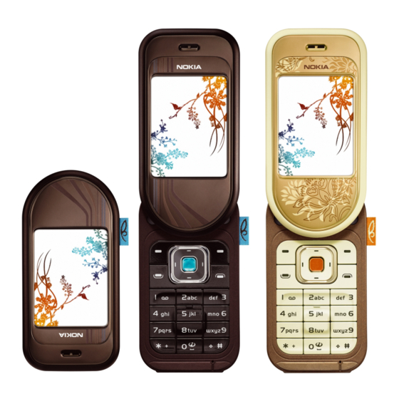
RM-70 General information Nokia Customer Care Product selection The RM-70(Nokia 7370) is a triple band transceiver unit designed for the GSM900/1800/1900 networks, including EGSM. Figure 1 RM-70 product picture Key Features: • 180-degree rotator design with ergonomic tilt • EDGE tri-band phone •... -
Page 18: Features
• HSCSD Software and User interface features Software features • ISA OS 8.0s Platform • Nokia Series 40 User interface (UI): Java MIDP 2.0 UI features Imaging • Integrated 1.3-megapixel camera with full-screen landscape camera mode, with up to 8x digital zoom •... - Page 19 • HSCSD (high-speed circuit-switched data) Voice features • Voice dialing • Voice recorder • Integrated handsfree speaker Digital services • Video streaming services • Exclusive UI themes Issue 1 COMPANY CONFIDENTIAL Page 1 –7 Copyright © 2005 Nokia. All rights reserved.
-
Page 20: Accessories
Accessories Table 1 Battery and chargers Type Name Note: This phone is charged through the smaller Nokia standard interface (2.0 mm plug). The 3.5 mm standard charger can be used together with the CA-44 charger adapter. AC-3 Compact charger AC-4... -
Page 21: Table 5 Imaging And Lifestyle
RM-70 General information Nokia Customer Care Table 5 Imaging and lifestyle Type Name PT-6 Remote camera Issue 1 COMPANY CONFIDENTIAL Page 1 –9 Copyright © 2005 Nokia. All rights reserved. - Page 22 RM-70 Nokia Customer Care General information (This page left intentionally blank.) Page 1 –10 COMPANY CONFIDENTIAL Issue 1 Copyright © 2005 Nokia. All rights reserved.
- Page 23 Nokia Customer Care 2 — Parts and layouts Issue 1 COMPANY CONFIDENTIAL Page 2 –1 Copyright © 2005 Nokia. All rights reserved.
- Page 24 RM-70 Nokia Customer Care Parts and layouts (This page left intentionally blank.) Page 2 –2 COMPANY CONFIDENTIAL Issue 1 Copyright © 2005 Nokia. All rights reserved.
-
Page 25: Table Of Contents
Table 8 Component parts list (PWB 1lua_50a).....................2–9 List of Figures Figure 2 Exploded view............................2–5 Figure 3 Spare parts overview..........................2–6 Figure 4 RM-70 Main board component layout, bottom (1lua_50a)...............2–23 Figure 5 RM-70 Main board component layout, top (1lua_50a)..............2–24 Issue 1 COMPANY CONFIDENTIAL Page 2 –3... - Page 26 RM-70 Nokia Customer Care Parts and layouts (This page left intentionally blank.) Page 2 –4 COMPANY CONFIDENTIAL Issue 1 Copyright © 2005 Nokia. All rights reserved.
-
Page 27: Exploded View
RM-70 Parts and layouts Nokia Customer Care Exploded view Figure 2 Exploded view Issue 1 COMPANY CONFIDENTIAL Page 2 –5 Copyright © 2005 Nokia. All rights reserved. -
Page 28: Spare Parts Overview
RM-70 Nokia Customer Care Parts and layouts Spare parts overview Figure 3 Spare parts overview Page 2 –6 COMPANY CONFIDENTIAL Issue 1 Copyright © 2005 Nokia. All rights reserved. -
Page 29: Mechanical Parts List
I203 MICROPHONE I204* VOLUME KEY I205* POWER KEY I206* CAMERA KEY PWB KEYMAT ASSY I207* PWB KEYMAT I208 DOMESHEET (APAC & CHINA only) I304* I210 KEYMAT Issue 1 COMPANY CONFIDENTIAL Page 2 –7 Copyright © 2005 Nokia. All rights reserved. -
Page 30: Swap Phones
Table 7 Swap phones Region Colour E&A Warm Amber E&A Coffee Brown Warm Amber Coffee Brown Warm Amber Coffee Brown Warm Amber Coffee Brown Warm Amber Page 2 –8 COMPANY CONFIDENTIAL Issue 1 Copyright © 2005 Nokia. All rights reserved. -
Page 31: Component Parts List
Chipcap X7R 10% 16V 0402 Bottom C2019 Chipcap X7R 10% 16V 0402 Bottom C2020 Chipcap X7R 10% 16V 0402 C2070 CHIPTCAP 150U M 10V 6X3.2X1.5 Bottom 150u_10V Issue 1 COMPANY CONFIDENTIAL Page 2 –9 Copyright © 2005 Nokia. All rights reserved. - Page 32 C2200 CHIPCAP X5R 1U K 6V3 0603 C2201 CHIPCAP X5R 1U K 6V3 0603 C2202 Chipcap X7R 10% 50V 0402 C2203 Chipcap X7R 10% 50V 0402 Page 2 –10 COMPANY CONFIDENTIAL Issue 1 Copyright © 2005 Nokia. All rights reserved.
- Page 33 C2275 Chipcap X7R 10% 50V 0402 C2281 CHIPCAP X5R 1U K 6V3 0603 C2300 Chipcap X7R 10% 16V 0402 C2301 CHIPCAP X5R 22U M 6V3 0805 Issue 1 COMPANY CONFIDENTIAL Page 2 –11 Copyright © 2005 Nokia. All rights reserved.
- Page 34 CHIPCAP X5R 100N M 16V 0402 100n C2801 CHIPCAP X5R 100N M 16V 0402 100n C2802 CHIPCAP X5R 100N M 16V 0402 100n C2803 CHIPCAP X5R 100N M 16V 0402 100n Page 2 –12 COMPANY CONFIDENTIAL Issue 1 Copyright © 2005 Nokia. All rights reserved.
- Page 35 Bottom 220n C3303 CHIPCAP X5R 100N K 10V 0402 Bottom 100n C3304 Chipcap X7R 10% 16V 0402 Bottom C3305 CHIPCAP X5R 4U7 K 6V3 0603 Bottom Issue 1 COMPANY CONFIDENTIAL Page 2 –13 Copyright © 2005 Nokia. All rights reserved.
- Page 36 Chipcap X7R 10% 16V 0402 Bottom C6170 Chipcap X7R 10% 16V 0402 Bottom C6176 Chipcap 5% NP0 Bottom 100p C6178 Chipcap 5% NP0 Bottom C6179 Chipcap 5% NP0 Bottom Page 2 –14 COMPANY CONFIDENTIAL Issue 1 Copyright © 2005 Nokia. All rights reserved.
- Page 37 SM FUSE F 2.0A 32V Bottom G2200 RTC BACUP CAPAC 311 SIZE FOR 2.6V 4UAH 2.6V G7500 VCO 3296-3980MHZ 4-BAND MATSUSHITA 3296-3980M G7501 VCTCXO 38.4MHZ 2.5V 2MA 38.4MHz Issue 1 COMPANY CONFIDENTIAL Page 2 –15 Copyright © 2005 Nokia. All rights reserved.
- Page 38 600R/ 100MHz L2204 FERRITE BEAD 0.6R 600R/100MHZ 0402 600R/ 100MHz L2205 FERR.BEAD 220R/100M 2A 0R05 0603 220R/ 100MHz L2206 FERRITE BEAD 0.6R 600R/100MHZ 0402 600R/ 100MHz Page 2 –16 COMPANY CONFIDENTIAL Issue 1 Copyright © 2005 Nokia. All rights reserved.
- Page 39 100MHz L7011 FERR.BEAD 240R7100M 0.4A 0R4 0402 Bottom 240R/ 100MHz L7500 CHIP COIL 12N J Q31/800M 0402 12nH L7501 CHIP COIL 12N J Q31/800M 0402 12nH Issue 1 COMPANY CONFIDENTIAL Page 2 –17 Copyright © 2005 Nokia. All rights reserved.
- Page 40 CHIP VARISTOR VWM14V VC50V 0402 Bottom 14V/50V R2100 ASIP SINGLE ENDED MICROPHONE INTERF BGA8 R2101 Resistor 5% 63mW 220R R2102 Chipres 0W06 jumper 0402 R2103 Chipres 0W06 jumper 0402 Page 2 –18 COMPANY CONFIDENTIAL Issue 1 Copyright © 2005 Nokia. All rights reserved.
- Page 41 4x33R R2414 RES NETWORK 0W03 4X100R J 0804 Bottom 4x100R R2415 RES NETWORK 0W03 4X100R J 0804 Bottom 4x100R R2417 NTC RES 47K J B=4050+-3% 0402 Issue 1 COMPANY CONFIDENTIAL Page 2 –19 Copyright © 2005 Nokia. All rights reserved.
- Page 42 100k R6161 Chipres 0W06 jumper 0402 Bottom R7000 CHIPRES JUMPER 0603 Bottom R7501 Resistor 5% 63mW R7502 CHIPRES 0W06 10K F 0402 R7503 Resistor 5% 63mW Page 2 –20 COMPANY CONFIDENTIAL Issue 1 Copyright © 2005 Nokia. All rights reserved.
- Page 43 100MHz Z2001 FERRITE BEAD 0.6R 600R/100MHZ 0402 Bottom 600R/ 100MHz Z2003 FERRITE BEAD 0.6R 600R/100MHZ 0402 Bottom 600R/ 100MHz Z2400 ASIP 10-CH ESD EMI FILTER BGA25 Issue 1 COMPANY CONFIDENTIAL Page 2 –21 Copyright © 2005 Nokia. All rights reserved.
-
Page 44: Non Replaceable Parts
These parts must not be replaced: Name Comment RAP GSM Placed under shielding and is therefore critical and difficult to replace. Module ID Only used in production. component Page 2 –22 COMPANY CONFIDENTIAL Issue 1 Copyright © 2005 Nokia. All rights reserved. -
Page 45: Component Layouts
Parts and layouts Nokia Customer Care Component layouts See also large scale layouts in the Schematics section. Figure 4 RM-70 Main board component layout, bottom (1lua_50a) Issue 1 COMPANY CONFIDENTIAL Page 2 –23 Copyright © 2005 Nokia. All rights reserved. - Page 46 RM-70 Nokia Customer Care Parts and layouts Figure 5 RM-70 Main board component layout, top (1lua_50a) Page 2 –24 COMPANY CONFIDENTIAL Issue 1 Copyright © 2005 Nokia. All rights reserved.
- Page 47 Nokia Customer Care 3 — Service Software Instructions Issue 1 COMPANY CONFIDENTIAL Page 3 –1 Copyright © 2005 Nokia. All rights reserved.
- Page 48 RM-70 Nokia Customer Care Service Software Instructions (This page left intentionally blank.) Page 3 –2 COMPANY CONFIDENTIAL Issue 1 Copyright © 2005 Nokia. All rights reserved.
- Page 49 Figure 27 Finish flash update..........................3–23 Figure 28 Flash directory window........................3–24 Figure 29 Prommer software update finished....................3–24 Figure 30 Prommer Maintenance window......................3–25 Figure 31 Box activation............................3–26 Figure 32 Deactivation warning.........................3–26 Issue 1 COMPANY CONFIDENTIAL Page 3 –3 Copyright © 2005 Nokia. All rights reserved.
- Page 50 RM-70 Nokia Customer Care Service Software Instructions (This page left intentionally blank.) Page 3 –4 COMPANY CONFIDENTIAL Issue 1 Copyright © 2005 Nokia. All rights reserved.
-
Page 51: Phoenix Installation Steps In Brief
3. Install the phone-specific data package. 4. Configure users. 5. Manage connection settings (depends on the tools you are using). If you use FPS-8: • Update FPS-8 software • Activate FPS-8 Issue 1 COMPANY CONFIDENTIAL Page 3 –5 Copyright © 2005 Nokia. All rights reserved. -
Page 52: Installing Phoenix
Press the F1 key or the feature’s Help button to activate a Help file. Steps phoenix_service_sw_2004_39_x_xx.exe ). 1. To start the installation, run the application file (for example, Welcome dialogue, click Next. 2. In the Page 3 –6 COMPANY CONFIDENTIAL Issue 1 Copyright © 2005 Nokia. All rights reserved. - Page 53 Select Yes... to reboot the PC immediately or No... to reboot the PC manually afterwards. After the reboot, all components are registered. Phoenix does not work, if the components have not been registered. Note: Issue 1 COMPANY CONFIDENTIAL Page 3 –7 Copyright © 2005 Nokia. All rights reserved.
-
Page 54: Updating Phoenix Installation
Windows Control Panel. the application from the • If you try to install an older version (for example, downgrade from a15_2004_24_7_55 to a14_2004_16_4_47), installation will be interrupted. Page 3 –8 COMPANY CONFIDENTIAL Issue 1 Copyright © 2005 Nokia. All rights reserved. -
Page 55: Uninstalling Phoenix
Phoenix Uninstalling Context Phoenix service software manually from the Windows Control Panel. You can uninstall Steps 1. Open the Windows Control Panel, and choose Add/Remove Programs. Issue 1 COMPANY CONFIDENTIAL Page 3 –9 Copyright © 2005 Nokia. All rights reserved. - Page 56 Nokia Customer Care Service Software Instructions Phoenix , choose Phoenix Service Software→Change/Remove→Remove . 2. To uninstall Figure 10 Remove program The progress of the uninstallation is shown. Page 3 –10 COMPANY CONFIDENTIAL Issue 1 Copyright © 2005 Nokia. All rights reserved.
-
Page 57: Repairing Phoenix Installation
PC when you run the repair setup. Steps 1. Open Windows Control Panel→Add/Remove Programs . 2. Choose Phoenix Service Software→Change/Remove . Issue 1 COMPANY CONFIDENTIAL Page 3 –11 Copyright © 2005 Nokia. All rights reserved. -
Page 58: Phone Data Package Overview
• Files for type label printing • Validation file for the fault log repair data reporting system • All product-specific configuration files for Phoenix software components Data files are stored in C:\Program Files\Nokia\Phoenix (default). Installing phone data package Before you begin Phoenix service software and service tools •... - Page 59 Steps XX-XX_dp_EA_ v_1_0.exe ), 1. To start the installation, run the application file (for example, Wait for the installation files to be extracted. 2. Click Next. Issue 1 COMPANY CONFIDENTIAL Page 3 –13 Copyright © 2005 Nokia. All rights reserved.
- Page 60 3. In the following view you can see the contents of the data package. Read the text carefully. There is Phoenix version required with this data package. information about the Figure 13 Data package setup information 4. To continue, click Next. Page 3 –14 COMPANY CONFIDENTIAL Issue 1 Copyright © 2005 Nokia. All rights reserved.
- Page 61 Figure 14 Data package destination folder Phoenix is installed, and the directory is shown. The InstallShield Wizard checks where 6. To start copying the files, click Next. Issue 1 COMPANY CONFIDENTIAL Page 3 –15 Copyright © 2005 Nokia. All rights reserved.
-
Page 62: Uninstalling Phone Data Package
Steps XX-XX_dp_EA_v_1_0.exe ) from your computer. 1. Locate the data package installation file (e.g. 2. To start the uninstallation procedure, double-click the data package installation file. Page 3 –16 COMPANY CONFIDENTIAL Issue 1 Copyright © 2005 Nokia. All rights reserved. - Page 63 Figure 17 Finishing data package uninstallation Alternative steps • You can also uninstall the data package manually from Control Panel→Add/Remove Programs→xx-xx* Phone Data Package . (*= type designator of the phone). Issue 1 COMPANY CONFIDENTIAL Page 3 –17 Copyright © 2005 Nokia. All rights reserved.
-
Page 64: Configuring Users In Phoenix
Windows Control Panel. If the problem persists, contact the local PC support. Steps Phoenix , and log in. 1. Start 2. Choose File→Manage Connections..Page 3 –18 COMPANY CONFIDENTIAL Issue 1 Copyright © 2005 Nokia. All rights reserved. - Page 65 • RX_BUFFER_SIZE: Use the default value, and click Next. iii For an FPS-8 flash prommer, choose the following connection settings: • Media: FPS-8 • PORT_NUM: COM Port where FPS-8 is connected • COMBOX_DEF_MEDIA: FBUS Issue 1 COMPANY CONFIDENTIAL Page 3 –19 Copyright © 2005 Nokia. All rights reserved.
-
Page 66: Installing Flash Support Files For Fps-8 And Fps-10
• A separate installation package for flash support files is available. The files can be updated according to Phoenix data package releases. these instructions, if updates appear between Page 3 –20 COMPANY CONFIDENTIAL Issue 1 Copyright © 2005 Nokia. All rights reserved. - Page 67 Figure 25 Flash installation interrupted If an older version exists on your PC and it needs to be updated, click Next to continue installation. Issue 1 COMPANY CONFIDENTIAL Page 3 –21 Copyright © 2005 Nokia. All rights reserved.
- Page 68 To continue, click Next. Figure 26 Flash destination folder When installing the flash update files for the first time, you may choose another location by selecting Browse (not recommended). Page 3 –22 COMPANY CONFIDENTIAL Issue 1 Copyright © 2005 Nokia. All rights reserved.
-
Page 69: Updating Fps-8 And Fps-10 Flash Prommer Software
Updating FPS-8 and FPS-10 flash prommer software Steps Phoenix service software, and log in. 1. Start 2. Choose the correct connection for your flash prommer: File→Manage Connections... 3. Choose Flashing→Prommer maintenance . Issue 1 COMPANY CONFIDENTIAL Page 3 –23 Copyright © 2005 Nokia. All rights reserved. - Page 70 Service Software Instructions fps8upd.ini (for FPS-8) 4. To update the FPS-8/FPS-10 software, click Update, and select the appropriate file fpsxupd.ini (for FPS-10) from C:\Program Files\Nokia\Phoenix\Flash . Figure 28 Flash directory window Tip: All files can be loaded separately to the prommer used. To do this, click the right mouse Flash Box Files pane and select the file type(s) to be loaded.
-
Page 71: Activating Fps-8
FPS-8 activation request sheet in the FPS-8 sales package, and follow the instructions given. First fill in the 00000.in ), copy it to the C:\ProgramFiles\Nokia\Phoenix When activation file is received (for example, \BoxActivation directory on your computer (this directory is created when Phoenix is installed). -
Page 72: Deactivating Fps-8
Prommer Maintenance window, click Deactivate. 3. In the 4. To confirm the deactivation, click Yes. Figure 32 Deactivation warning The box is deactivated. 5. To complete the deactivation, restart FPS-8. Page 3 –26 COMPANY CONFIDENTIAL Issue 1 Copyright © 2005 Nokia. All rights reserved. - Page 73 Nokia Customer Care 4 — Service Tools and Service Concepts Issue 1 COMPANY CONFIDENTIAL Page 4 –1 Copyright © 2005 Nokia. All rights reserved.
- Page 74 RM-70 Nokia Customer Care Service Tools and Service Concepts (This page left intentionally blank.) Page 4 –2 COMPANY CONFIDENTIAL Issue 1 Copyright © 2005 Nokia. All rights reserved.
- Page 75 Service concepts..............................4–12 POS flash concept............................4–12 FPS-10 flash concept ............................4–12 Module jig flash concept with FPS-10......................4–14 Module jig tuning concept..........................4–15 RF testing and RF/BB tuning concept ......................4–15 Issue 1 COMPANY CONFIDENTIAL Page 4 –3 Copyright © 2005 Nokia. All rights reserved.
- Page 76 RM-70 Nokia Customer Care Service Tools and Service Concepts (This page left intentionally blank.) Page 4 –4 COMPANY CONFIDENTIAL Issue 1 Copyright © 2005 Nokia. All rights reserved.
-
Page 77: Service Tools
Nokia Customer Care Service tools The table below gives a short overview of service tools that can be used for testing, error analysis and repair of product RM-70, refer to various concepts. CA-35S Power cable CA-35S is a power cable for connecting, for example, the FPS-10 flash prommer to the Point-Of-Sales (POS) flash adapter. - Page 78 4 Connect an FBUS cable (if necessary). 5 Start Phoenix service software. Note: Phoenix enables CU-4 regulators via USB when it is started. Reconnecting the power supply requires a Phoenix restart. Page 4 –6 COMPANY CONFIDENTIAL Issue 1 Copyright © 2005 Nokia. All rights reserved.
- Page 79 • LAN to FBUS/Flashbus and USB conversion • Vusb output switchable by PC command FPS-10 sales package includes: • FPS-10 prommer • Power Supply with 5 country specific cords • USB cable Issue 1 COMPANY CONFIDENTIAL Page 4 –7 Copyright © 2005 Nokia. All rights reserved.
- Page 80 Bluetooth. An ACP-8x charger is needed for BER testing and an AXS-4 cable in case of cordless interface usage testing . Sales package includes: • JBT-9 test box • Installation and warranty information Page 4 –8 COMPANY CONFIDENTIAL Issue 1 Copyright © 2005 Nokia. All rights reserved.
- Page 81 • Provides galvanic connection to all needed test pads in module • UI test interface • Audio components MIC, earpiece, stereo IHF • Unlimited operation of a disassembled RM-70 phone module • Power supply via CU-4 Note: CU-4 is needed to operate MJ-62. CU-4 is not part of the MJ-62 sales package and has to be ordered separately.
- Page 82 The front camera removal tool SS-45 is used to remove/attach the front camera module from/to the socket. SS-46 Interface adapter SS-46 acts as an interface adapter between a product-specific flash adapter and FPS-10. Page 4 –10 COMPANY CONFIDENTIAL Issue 1 Copyright © 2005 Nokia. All rights reserved.
- Page 83 This stencil is to be used together with RJ-93 and covering FEM module. XCS-4 Modular cable XCS-4 is a shielded (one specially shielded conductor) modular cable for flashing and service purposes. Issue 1 COMPANY CONFIDENTIAL Page 4 –11 Copyright © 2005 Nokia. All rights reserved.
-
Page 84: Jbt-9
Do not connect an ACP-charger to the phone! This may damage the FEM module. FPS-10 flash concept Note: Do not connect an ACP-charger to the phone! This may damage the FEM module. Page 4 –12 COMPANY CONFIDENTIAL Issue 1 Copyright © 2005 Nokia. All rights reserved. - Page 85 RM-70 Service Tools and Service Concepts Nokia Customer Care Issue 1 COMPANY CONFIDENTIAL Page 4 –13 Copyright © 2005 Nokia. All rights reserved.
-
Page 86: Module Jig Flash Concept With Fps-10
RM-70 Nokia Customer Care Service Tools and Service Concepts Module jig flash concept with FPS-10 Page 4 –14 COMPANY CONFIDENTIAL Issue 1 Copyright © 2005 Nokia. All rights reserved. -
Page 87: Module Jig Tuning Concept
In this case, the DAU-9S cable must be disconnected for a couple of seconds, then reconnected and the phone powers up again. Issue 1 COMPANY CONFIDENTIAL Page 4 –15 Copyright © 2005 Nokia. All rights reserved. - Page 88 RM-70 Nokia Customer Care Service Tools and Service Concepts Page 4 –16 COMPANY CONFIDENTIAL Issue 1 Copyright © 2005 Nokia. All rights reserved.
- Page 89 Nokia Customer Care 5 — Disassembly and reassembly instructions Issue 1 COMPANY CONFIDENTIAL Page 5 –1 Copyright © 2005 Nokia. All rights reserved.
- Page 90 RM-70 Nokia Customer Care Disassembly and reassembly instructions (This page left intentionally blank.) Page 5 –2 COMPANY CONFIDENTIAL Issue 1 Copyright © 2005 Nokia. All rights reserved.
- Page 91 Disassembly and reassembly instructions Nokia Customer Care Table of Contents Disassembly instructions (upper block).......................5–5 Reassembly instructions (upper block)........................5–9 Disassembly instructions (lower block)......................5–10 Reassembly instructions (upper block)......................5–18 Replacing SIM flap..............................5–20 Issue 1 COMPANY CONFIDENTIAL Page 5 –3 Copyright © 2005 Nokia. All rights reserved.
- Page 92 RM-70 Nokia Customer Care Disassembly and reassembly instructions (This page left intentionally blank.) Page 5 –4 COMPANY CONFIDENTIAL Issue 1 Copyright © 2005 Nokia. All rights reserved.
-
Page 93: Disassembly Instructions (Upper Block)
Disassembly instructions (upper block) Steps You need the following tools. Always protect all windows with a plastic film. Open the E-COVER and remove the battery, if it is inserted. Issue 1 COMPANY CONFIDENTIAL Page 5 –5 Copyright © 2005 Nokia. All rights reserved. - Page 94 Slide the SRT-6 around the covers and keep the gap open. Unlock the retaining clips separately. Go ahead near the SWIVEL area. This is the last clip to be unlocked. Page 5 –6 COMPANY CONFIDENTIAL Issue 1 Copyright © 2005 Nokia. All rights reserved.
- Page 95 Also, protect the inner side of the window with a plastic film. 10. Carefully unlock the BOARD TO BOARD CONNECTOR. 11. Unlock four clips at the B-COVER, which hold theUI-SHIELD into the B-COVER. Issue 1 COMPANY CONFIDENTIAL Page 5 –7 Copyright © 2005 Nokia. All rights reserved.
- Page 96 13. Open the four clips which hold the LCD into the UI-SHIELD. Do not bend the clips too much to keep the part reusable for assembly. 14. Lift out the LCD. 15. To avoid dust and scratches, protect the LCD with a plastic film. Page 5 –8 COMPANY CONFIDENTIAL Issue 1 Copyright © 2005 Nokia. All rights reserved.
-
Page 97: Reassembly Instructions (Upper Block)
18. Separate the UPPER BLOCK from the LOWER BLOCK. Reassembly instructions (upper block) Steps in reversed order , from step 18 to step 17. 1. Follow the disassembly instructions Issue 1 COMPANY CONFIDENTIAL Page 5 –9 Copyright © 2005 Nokia. All rights reserved. -
Page 98: Disassembly Instructions (Lower Block)
3. Follow the disassembly instructions Note: Pay special attention to step 16. Disassembly instructions (lower block) Steps Always protect all windows with a plastic film. Remove the E-COVER. Page 5 –10 COMPANY CONFIDENTIAL Issue 1 Copyright © 2005 Nokia. All rights reserved. - Page 99 Open the middle snaps of the D-COVER, using a slotted screwdriver. Use the SRT-6 to open the snaps of the D-COVER ASSY on the right side. Then... Issue 1 COMPANY CONFIDENTIAL Page 5 –11 Copyright © 2005 Nokia. All rights reserved.
- Page 100 RM-70 Nokia Customer Care Disassembly and reassembly instructions ...at the top side and..at the left side. Remove the D-COVER. 10. Remove the CAMERA GASKET. Page 5 –12 COMPANY CONFIDENTIAL Issue 1 Copyright © 2005 Nokia. All rights reserved.
- Page 101 14. Stick the dental tool under the ANTENNA MODULE (The pike of the dental tool is visible in the marked hole). Now pull the tool to the shown direction. Issue 1 COMPANY CONFIDENTIAL Page 5 –13 Copyright © 2005 Nokia. All rights reserved.
- Page 102 19. Unsrew the three SWIVEL screws Torx Plus® size 6 in the following order. Note: For assembly use the reverse order and apply a torque of 25 Ncm +/- 2 Ncm. Always use new screws! Page 5 –14 COMPANY CONFIDENTIAL Issue 1 Copyright © 2005 Nokia. All rights reserved.
- Page 103 20. Separate the ENGINE MODULE from the C-COVER ASSY. 21. To remove the SIM FLAP start in the order shown. 22. Now remove the other side. Issue 1 COMPANY CONFIDENTIAL Page 5 –15 Copyright © 2005 Nokia. All rights reserved.
- Page 104 23. Remove the BLUETOOTH ANTENNA with tweezers. 24. Remove the MICROPHONE with the dental tool. 25. Remove both IHF SPEAKERS with tweezers. 26. Separate the C-COVER ASSY from the UPPER BLOCK. Page 5 –16 COMPANY CONFIDENTIAL Issue 1 Copyright © 2005 Nokia. All rights reserved.
- Page 105 28. Remove the PWB KEYMAT ASSY. 29. Use a DC PLUG to remove the DC-JACK. 30. There are five clips, holding the LABEL COVER into the D-cover. Issue 1 COMPANY CONFIDENTIAL Page 5 –17 Copyright © 2005 Nokia. All rights reserved.
-
Page 106: Reassembly Instructions (Upper Block)
, from step 32 to step 13. 1. Follow the disassembly instructions Note: Pay special attention to step 19. 2. Mind the correct positioning of the CAMERA MODULE. Page 5 –18 COMPANY CONFIDENTIAL Issue 1 Copyright © 2005 Nokia. All rights reserved. - Page 107 6. Start placing the KEYMAT at the marked positions. 7. Make sure to have all clips locked properly. in reversed order , from step 3 to step 1. 8. Follow the disassembly instructions Issue 1 COMPANY CONFIDENTIAL Page 5 –19 Copyright © 2005 Nokia. All rights reserved.
-
Page 108: Replacing Sim Flap
2. The SIM CARD READER and the SIM FLAP is provided as one spare part. Separate it and assemble the SIM FLAP as shown. Page 5 –20 COMPANY CONFIDENTIAL Issue 1 Copyright © 2005 Nokia. All rights reserved. - Page 109 Nokia Customer Care 6 — BB Troubleshooting and Manual Tuning Guide Issue 1 COMPANY CONFIDENTIAL Page 6 –1 Copyright © 2005 Nokia. All rights reserved.
- Page 110 RM-70 Nokia Customer Care BB Troubleshooting and Manual Tuning Guide (This page left intentionally blank.) Page 6 –2 COMPANY CONFIDENTIAL Issue 1 Copyright © 2005 Nokia. All rights reserved.
- Page 111 Certificate restoring for BB5.0 products.......................6–40 Energy management calibration........................6–46 List of Tables Table 9 Display module troubleshooting cases....................6–17 Table 10 Pixel defects............................6–17 Table 11 Calibration value limits........................6–46 Issue 1 COMPANY CONFIDENTIAL Page 6 –3 Copyright © 2005 Nokia. All rights reserved.
- Page 112 Figure 37 Single-ended output waveform of the HP_in_Ext_out loop when microphone is connected..6–25 Figure 38 BER test result............................6–36 Figure 39 Bluetooth self tests in Phoenix......................6–37 Page 6 –4 COMPANY CONFIDENTIAL Issue 1 Copyright © 2005 Nokia. All rights reserved.
-
Page 113: Baseband Troubleshooting Overview
1 Swivel detection troubleshooting Camera flash LED does not work 1 Flash LED Bluetooth does not work 1 Bluetooth (BT) FM radio does not work 1 FM radio Issue 1 COMPANY CONFIDENTIAL Page 6 –5 Copyright © 2005 Nokia. All rights reserved. -
Page 114: Power And Charging Troubleshooting
RM-70 Nokia Customer Care BB Troubleshooting and Manual Tuning Guide Power and charging troubleshooting General power checking troubleshooting Troubleshooting flow Page 6 –6 COMPANY CONFIDENTIAL Issue 1 Copyright © 2005 Nokia. All rights reserved. -
Page 115: Battery Current Measuring Fault Troubleshooting
RM-70 BB Troubleshooting and Manual Tuning Guide Nokia Customer Care Battery current measuring fault troubleshooting Troubleshooting flow Issue 1 COMPANY CONFIDENTIAL Page 6 –7 Copyright © 2005 Nokia. All rights reserved. -
Page 116: Clocking Troubleshooting
RM-70 Nokia Customer Care BB Troubleshooting and Manual Tuning Guide Clocking troubleshooting Troubleshooting flow Page 6 –8 COMPANY CONFIDENTIAL Issue 1 Copyright © 2005 Nokia. All rights reserved. -
Page 117: Interface Troubleshooting
• The image may be blurred, though it does not show in the viewfinder • Analyse the picture from your PC monitor, full colour setting is recommended • If possible, compare with a picture of the same motive taken with a similar Nokia device Issue 1 COMPANY CONFIDENTIAL Page 6 –9... -
Page 118: Camera Hardware Failure Message Troubleshooting
RM-70 Nokia Customer Care BB Troubleshooting and Manual Tuning Guide Camera hardware failure message troubleshooting Troubleshooting flow Page 6 –10 COMPANY CONFIDENTIAL Issue 1 Copyright © 2005 Nokia. All rights reserved. -
Page 119: Camera Hardware Troubleshooting
RM-70 BB Troubleshooting and Manual Tuning Guide Nokia Customer Care Camera hardware troubleshooting Camera hardware troubleshooting Issue 1 COMPANY CONFIDENTIAL Page 6 –11 Copyright © 2005 Nokia. All rights reserved. -
Page 120: Front Camera Viewfinder Troubleshooting
RM-70 Nokia Customer Care BB Troubleshooting and Manual Tuning Guide Front camera viewfinder troubleshooting Troubleshooting flow Page 6 –12 COMPANY CONFIDENTIAL Issue 1 Copyright © 2005 Nokia. All rights reserved. -
Page 121: Front Camera Bad Image Quality Troubleshooting
RM-70 BB Troubleshooting and Manual Tuning Guide Nokia Customer Care Front camera bad image quality troubleshooting Troubleshooting flow Issue 1 COMPANY CONFIDENTIAL Page 6 –13 Copyright © 2005 Nokia. All rights reserved. -
Page 122: Combo Memory Troubleshooting
RM-70 Nokia Customer Care BB Troubleshooting and Manual Tuning Guide COMBO memory troubleshooting Troubleshooting flow Page 6 –14 COMPANY CONFIDENTIAL Issue 1 Copyright © 2005 Nokia. All rights reserved. -
Page 123: Flash Programming Fault Troubleshooting
RM-70 BB Troubleshooting and Manual Tuning Guide Nokia Customer Care Flash programming fault troubleshooting Part 1 Issue 1 COMPANY CONFIDENTIAL Page 6 –15 Copyright © 2005 Nokia. All rights reserved. -
Page 124: User Interface Troubleshooting
• The display is in a normal mode when the phone is in active use. • Display is in a partial idle mode when the phone is in the screen saver mode. Page 6 –16 COMPANY CONFIDENTIAL Issue 1 Copyright © 2005 Nokia. All rights reserved. - Page 125 The display module cannot be repaired. 2. Check that the cellular engine is working normally. To check the functionality, connect the phone to a docking station. Phoenix service software. ii Start Issue 1 COMPANY CONFIDENTIAL Page 6 –17 Copyright © 2005 Nokia. All rights reserved.
- Page 126 APE ID). 3. Proceed to the display troubleshooting flowcharts. Phoenix to find the detailed fault mode. Use the Display Test tool in Page 6 –18 COMPANY CONFIDENTIAL Issue 1 Copyright © 2005 Nokia. All rights reserved.
-
Page 127: Display Troubleshooting
RM-70 BB Troubleshooting and Manual Tuning Guide Nokia Customer Care Display troubleshooting Troubleshooting flow Issue 1 COMPANY CONFIDENTIAL Page 6 –19 Copyright © 2005 Nokia. All rights reserved. -
Page 128: Backlight Troubleshooting
It affects both display and keypad. Keyboard backlights can be turned ON/OFF separately but not without switching on the display lights. Display and keyboard backlight troubleshooting Page 6 –20 COMPANY CONFIDENTIAL Issue 1 Copyright © 2005 Nokia. All rights reserved. -
Page 129: Led Driver Troubleshooting
RM-70 BB Troubleshooting and Manual Tuning Guide Nokia Customer Care LED driver troubleshooting LED driver troubleshooting Issue 1 COMPANY CONFIDENTIAL Page 6 –21 Copyright © 2005 Nokia. All rights reserved. -
Page 130: Swivel Detection Troubleshooting
Swivel detection troubleshooting Audio troubleshooting Audio troubleshooting test instructions Differential external earpiece and internal earpiece outputs can be measured either with a single-ended or a differential probe. Page 6 –22 COMPANY CONFIDENTIAL Issue 1 Copyright © 2005 Nokia. All rights reserved. - Page 131 Earpiece, internal microphone and speaker are in place during measurement. Applying a headset accessory during measurement causes a significant drop in measured quantities. The gain values presented in the table apply for a differential output vs. single-ended/differential input. Issue 1 COMPANY CONFIDENTIAL Page 6 –23 Copyright © 2005 Nokia. All rights reserved.
- Page 132 1360 Earpiece GND) HSEAR R N and GND HSEAR P, HSEAR N and HSEAR R P, HSEAR R N and GND HSEAR P, HSEAR N and Page 6 –24 COMPANY CONFIDENTIAL Issue 1 Copyright © 2005 Nokia. All rights reserved.
- Page 133 Figure 36 Differential output waveform of the Ext_in_IHF_out out loop measurement when speaker is connected. Figure 37 Single-ended output waveform of the HP_in_Ext_out loop when microphone is connected. Issue 1 COMPANY CONFIDENTIAL Page 6 –25 Copyright © 2005 Nokia. All rights reserved.
-
Page 134: Internal Earpiece Troubleshooting
RM-70 Nokia Customer Care BB Troubleshooting and Manual Tuning Guide Internal earpiece troubleshooting Troubleshooting flow Page 6 –26 COMPANY CONFIDENTIAL Issue 1 Copyright © 2005 Nokia. All rights reserved. -
Page 135: Internal Microphone Troubleshooting
RM-70 BB Troubleshooting and Manual Tuning Guide Nokia Customer Care Internal microphone troubleshooting Troubleshooting flow Issue 1 COMPANY CONFIDENTIAL Page 6 –27 Copyright © 2005 Nokia. All rights reserved. -
Page 136: Ihf Troubleshooting
RM-70 Nokia Customer Care BB Troubleshooting and Manual Tuning Guide IHF troubleshooting Troubleshooting flow Page 6 –28 COMPANY CONFIDENTIAL Issue 1 Copyright © 2005 Nokia. All rights reserved. -
Page 137: External Microphone Troubleshooting
RM-70 BB Troubleshooting and Manual Tuning Guide Nokia Customer Care External microphone troubleshooting Troubleshooting flow Issue 1 COMPANY CONFIDENTIAL Page 6 –29 Copyright © 2005 Nokia. All rights reserved. -
Page 138: External Earpiece Troubleshooting
RM-70 Nokia Customer Care BB Troubleshooting and Manual Tuning Guide External earpiece troubleshooting Troubleshooting flow Page 6 –30 COMPANY CONFIDENTIAL Issue 1 Copyright © 2005 Nokia. All rights reserved. -
Page 139: Introduction To Acoustics Troubleshooting
The phone should be dry and clean, and no objects must be located in such a way that they close any of the holes. Issue 1 COMPANY CONFIDENTIAL Page 6 –31 Copyright © 2005 Nokia. All rights reserved. -
Page 140: Earpiece Troubleshooting
RM-70 Nokia Customer Care BB Troubleshooting and Manual Tuning Guide Earpiece troubleshooting Troubleshooting flow Page 6 –32 COMPANY CONFIDENTIAL Issue 1 Copyright © 2005 Nokia. All rights reserved. -
Page 141: Ihf Troubleshooting
RM-70 BB Troubleshooting and Manual Tuning Guide Nokia Customer Care IHF troubleshooting Troubleshooting flow Issue 1 COMPANY CONFIDENTIAL Page 6 –33 Copyright © 2005 Nokia. All rights reserved. -
Page 142: Microphone Troubleshooting
RM-70 Nokia Customer Care BB Troubleshooting and Manual Tuning Guide Microphone troubleshooting Troubleshooting flow Page 6 –34 COMPANY CONFIDENTIAL Issue 1 Copyright © 2005 Nokia. All rights reserved. -
Page 143: Bluetooth Troubleshooting
7. Place the JBT-9 box near (within 10 cm) the BT antenna and click Run BER Test. Results Bit Error Rate (BER) Tests pane in the Bluetooth LOCALS window. Bit Error Rate test result is displayed in the Issue 1 COMPANY CONFIDENTIAL Page 6 –35 Copyright © 2005 Nokia. All rights reserved. -
Page 144: Bluetooth Self Tests In Phoenix
4. From the Mode drop-down menu, set mode to Local. 5. Choose Testing→Self Tests. Self Tests window check the following Bluetooth related tests: 6. In the • ST_LPRF_IF_TEST • ST_LPRF_AUDIO_LINES_TEST • ST_BT_WAKEUP_TEST Page 6 –36 COMPANY CONFIDENTIAL Issue 1 Copyright © 2005 Nokia. All rights reserved. -
Page 145: Bluetooth Ber Failure Troubleshooting
Bluetooth BER failure troubleshooting Context Basic encoding rules, BER, is a self-identifying and self-delimiting encoding scheme, which means that each data value can be identified, extracted and decoded individually. Issue 1 COMPANY CONFIDENTIAL Page 6 –37 Copyright © 2005 Nokia. All rights reserved. - Page 146 RM-70 Nokia Customer Care BB Troubleshooting and Manual Tuning Guide Part 1: Bluetooth self test passed but BER test failed Page 6 –38 COMPANY CONFIDENTIAL Issue 1 Copyright © 2005 Nokia. All rights reserved.
- Page 147 RM-70 BB Troubleshooting and Manual Tuning Guide Nokia Customer Care Part 2: Bluetooth self test failed Issue 1 COMPANY CONFIDENTIAL Page 6 –39 Copyright © 2005 Nokia. All rights reserved.
-
Page 148: Bluetooth Audio And Ui Activation Troubleshooting
All tunings (RF & Baseband, UI) must be done after performing the certificate restoring procedure. The procedure for certificate restoring is the following: • Flash the phone with the latest available software using FPS-8 or FPS-10. Page 6 –40 COMPANY CONFIDENTIAL Issue 1 Copyright © 2005 Nokia. All rights reserved. - Page 149 Note: USB flashing does not work for a dead BB5.0 phone. • Create a request file. • Send the file to Nokia by e-mail. Use the following addresses depending on your location: • APAC: sydney.service@nokia.com • CHINA: repair.ams@nokia.com • E&A: salo.repair@nokia.com •...
- Page 150 Flash Type must be set to Phone as Manufactured. To continue, click Start. Progress bars and messages on the screen show actions during phone programming, please wait. Page 6 –42 COMPANY CONFIDENTIAL Issue 1 Copyright © 2005 Nokia. All rights reserved.
- Page 151 Phoenix , choose File→Scan Product . To connect the phone with ii Choose Tools→Certificate Restore . iii To choose a location for the request file, click Browse. Issue 1 COMPANY CONFIDENTIAL Page 6 –43 Copyright © 2005 Nokia. All rights reserved.
- Page 152 Request file, click Start. To create the vi When the file for certificate restore has been created, send it to Nokia as an e-mail attachment. 3. Restore certificate. For this procedure, you must supply +12 V to CU-4 from an external power supply.
- Page 153 To write the file to phone, click Start. Next action Phoenix tuning functions. After a successful rewrite, you must retune the phone completely by using Important: Perform all tunings: RF, BB, and UI. Issue 1 COMPANY CONFIDENTIAL Page 6 –45 Copyright © 2005 Nokia. All rights reserved.
-
Page 154: Energy Management Calibration
Write and/or repeat the procedure again. Energy Management Calibration window. 10. To end the procedure, close the Page 6 –46 COMPANY CONFIDENTIAL Issue 1 Copyright © 2005 Nokia. All rights reserved. - Page 155 Nokia Customer Care 7 — RF Troubleshooting and Manual Tuning Guide Issue 1 COMPANY CONFIDENTIAL Page 7 –1 Copyright © 2005 Nokia. All rights reserved.
- Page 156 RM-70 Nokia Customer Care RF Troubleshooting and Manual Tuning Guide (This page left intentionally blank.) Page 7 –2 COMPANY CONFIDENTIAL Issue 1 Copyright © 2005 Nokia. All rights reserved.
- Page 157 Figure 42 RF Controls window..........................7–11 Figure 43 RF Controls window..........................7–14 Figure 44 Antenna module..........................7–14 Figure 45 Auto tuning concept with CMU200....................7–16 Figure 46 Rf channel filter calibration typical values..................7–17 Issue 1 COMPANY CONFIDENTIAL Page 7 –3 Copyright © 2005 Nokia. All rights reserved.
- Page 158 RM-70 Nokia Customer Care RF Troubleshooting and Manual Tuning Guide (This page left intentionally blank.) Page 7 –4 COMPANY CONFIDENTIAL Issue 1 Copyright © 2005 Nokia. All rights reserved.
-
Page 159: Introduction To Rf Troubleshooting
In GSM, the input signal can be either a real GSM signal or a CW signal that is 67.771kHz up from the carrier frequency. For service tool usage instructions, refer to section Service Tools and Service Concepts. Issue 1 COMPANY CONFIDENTIAL Page 7 –5 Copyright © 2005 Nokia. All rights reserved. -
Page 160: General Instructions For Rx Troubleshooting
When using DAU-9S select FBUS). iii From the File menu, choose product: File -> Choose Product -> xx-x* (* = type designator of the phone, eg. RM-70), or press Ctrl + R to scan product. iv From the toolbar, set operating mode to “Local”. -
Page 161: Reciever (Rx) Troubleshooting
Troubleshoot one band at a time. Start with the GSM900 and end with GSM1900. Receiver troubleshooting Apply a signal according to the table in General instructions for RX troubleshooting (page 7–6) Issue 1 COMPANY CONFIDENTIAL Page 7 –7 Copyright © 2005 Nokia. All rights reserved. - Page 162 RM-70 Nokia Customer Care RF Troubleshooting and Manual Tuning Guide Page 7 –8 COMPANY CONFIDENTIAL Issue 1 Copyright © 2005 Nokia. All rights reserved.
-
Page 163: Gsm Rx Chain Activation For Manual Measurements / Gsm Rssi Measurement
• Tx troubleshooting requires Tx operation. • Do not transmit on frequencies that are in use! • Transmitter can be controlled in the local mode for diagnostic purposes. Issue 1 COMPANY CONFIDENTIAL Page 7 –9 Copyright © 2005 Nokia. All rights reserved. - Page 164 From the File menu, choose product: File -> Choose Product -> xx-x* (* = type designator of the phone)RM-70), or pressCtrl + R to scan product. iv From the toolbar, set operating mode to “Local”. 5. EGSM900/1800/1900 troubleshooting RF Controls window: Testing ->...
- Page 165 Channel (RX and TX) TX power level GSM900 GSM1800 GSM1900 Figure 42 RF Controls window General instructions for TX troubleshooting Context • Tx troubleshooting requires Tx operation. Issue 1 COMPANY CONFIDENTIAL Page 7 –11 Copyright © 2005 Nokia. All rights reserved.
- Page 166 When using DAU-9S select FBUS driver). iii From the File menu, choose product: File -> Choose Product -> xx-x* (* = type designator of the phone)RM-70), or pressCtrl + R to scan product. iv From the toolbar, set operating mode to “Local”.
- Page 167 • Set Tx PA mode to “High” (Default). • Set power level (see table below) Band Channel (RX and TX) TX power level GSM900 GSM1800 GSM1900 Issue 1 COMPANY CONFIDENTIAL Page 7 –13 Copyright © 2005 Nokia. All rights reserved.
-
Page 168: Checking Antenna Functionality
GND2 has no DC connection to the other contacts. The antenna is functioning normally when the contacts function (Feed-GND1 = 0 Ω) Also check visually to make sure that the antenna is intact. Page 7 –14 COMPANY CONFIDENTIAL Issue 1 Copyright © 2005 Nokia. All rights reserved. -
Page 169: Synthesizer Troubleshooting
RM-70 RF Troubleshooting and Manual Tuning Guide Nokia Customer Care Synthesizer troubleshooting Synthesizer troubleshooting Issue 1 COMPANY CONFIDENTIAL Page 7 –15 Copyright © 2005 Nokia. All rights reserved. -
Page 170: Rf Tunings
• Cables: XRF-1 (RF cable), USB cable, GBIP cable and DAU-9S or one device including all. • Signal analyser (TX), signal generator (RX) and RF-splitter Figure 45 Auto tuning concept with CMU200 Page 7 –16 COMPANY CONFIDENTIAL Issue 1 Copyright © 2005 Nokia. All rights reserved. -
Page 171: System Mode Independent Manual Tunings
4. To save the values to the PMM (Phone Permanent Memory) area, click Write. Rf Channel Filter Calibration window, click Close. 5. To close the Results Figure 46 Rf channel filter calibration typical values Issue 1 COMPANY CONFIDENTIAL Page 7 –17 Copyright © 2005 Nokia. All rights reserved. -
Page 172: Pa (Power Amplifier) Detection
1. Connect the GSM connector of the module jig to a signal generator. Phoenix service software. 2. Start 3. From the Operating mode drop-down menu, set mode to Local. 4. Choose Tuning→GSM→Rx Calibration . Page 7 –18 COMPANY CONFIDENTIAL Issue 1 Copyright © 2005 Nokia. All rights reserved. - Page 173 Rx Calibration with band EGSM900 (step 1-3) pop-up window. Important: The calibration uses a non-modulated CW signal. Increase the signal generator level by cable attenuation and module jig probe attenuation. Issue 1 COMPANY CONFIDENTIAL Page 7 –19 Copyright © 2005 Nokia. All rights reserved.
- Page 174 8. Check that the tuning values are within the limits specified in the following table: Table 13 RF tuning limits in Rx calibration Unit GSM900 AFC Value -200 -105...62 AFC slope RSSI0 107...110 GSM1800 RSSI0 104...109 GSM1900 RSSI0 104...109 Page 7 –20 COMPANY CONFIDENTIAL Issue 1 Copyright © 2005 Nokia. All rights reserved.
-
Page 175: Rx Band Filter Response Compensation (Gsm)
Connect the GSM connector of the module jig to a signal generator. Phoenix service software. Start From the Operating mode drop-down menu, set mode to Local. Issue 1 COMPANY CONFIDENTIAL Page 7 –21 Copyright © 2005 Nokia. All rights reserved. - Page 176 Rx Band Connect the signal generator to the phone, and set frequency and amplitude as instructed in the Filter Response Compensation for EGSM900 pop-up window, step 1-3. Page 7 –22 COMPANY CONFIDENTIAL Issue 1 Copyright © 2005 Nokia. All rights reserved.
- Page 177 927.66771 MHz Ch. 1009 / 932.06771 MHz Ch. 37 / 942.46771 MHz Ch. 90 / 953.06771 MHz Ch. 114 / 957.86771 MHz Ch. 124 / 959.86771 MHz Issue 1 COMPANY CONFIDENTIAL Page 7 –23 Copyright © 2005 Nokia. All rights reserved.
- Page 178 Ch. 810 / 1989.86771 MHz Ch. 835 / 1994.86771 MHz 12. If the values are within the limits, click Next to continue to the next band. Page 7 –24 COMPANY CONFIDENTIAL Issue 1 Copyright © 2005 Nokia. All rights reserved.
-
Page 179: Gsm Transmitter Tunings
5. Select Band: GSM900 and click Start. 6. Click Next to start GSM1800 band TX IQ tuning. 7. Click Next to start GSM1900 band TX IQ tuning. 8. ClickFinish and then Close. Issue 1 COMPANY CONFIDENTIAL Page 7 –25 Copyright © 2005 Nokia. All rights reserved. -
Page 180: Tx Power Level Tuning (Gsm)
1. Connect the phone to a spectrum analyzer. Phoenix service software. 2. Start 3. From the Operating mode drop-down menu, set mode to Local. 4. Choose Tuning→GSM→Tx Power Level Tuning . Page 7 –26 COMPANY CONFIDENTIAL Issue 1 Copyright © 2005 Nokia. All rights reserved. - Page 181 Channel frequency: • 897.4MHz GSM900 • 1747.8MHz GSM1800 • 1880MHz GSM1900 Span 0 Hz Sweep time Trigger Video triggering (-10dBm) Resolution BW 3MHz Video BW 3MHz Issue 1 COMPANY CONFIDENTIAL Page 7 –27 Copyright © 2005 Nokia. All rights reserved.
- Page 182 9. Adjust power for all bold power levels to correspond the Target dBm column by pressing + or – keys. Next action Continue tuning the bold power levels of the GSM1800 and GSM1900 bands. You will see this message, if finished successfully: Page 7 –28 COMPANY CONFIDENTIAL Issue 1 Copyright © 2005 Nokia. All rights reserved.
- Page 183 Nokia Customer Care 8 — System module Issue 1 COMPANY CONFIDENTIAL Page 8 –1 Copyright © 2005 Nokia. All rights reserved.
- Page 184 RM-70 Nokia Customer Care System module (This page left intentionally blank.) Page 8 –2 COMPANY CONFIDENTIAL Issue 1 Copyright © 2005 Nokia. All rights reserved.
- Page 185 Table 20 Receiver characteristics........................8–24 List of Figures Figure 47 PWB overview............................8–6 Figure 48 System block diagram...........................8–7 Figure 49 Board and module connections......................8–8 Figure 50 BL-4B battery and battery connector....................8–10 Issue 1 COMPANY CONFIDENTIAL Page 8 –3 Copyright © 2005 Nokia. All rights reserved.
- Page 186 Figure 61 Internal microphone circuitry......................8–18 Figure 62 Internal speaker circuitry........................8–19 Figure 63 Vibra circuitry............................8–20 Figure 64 USB interface to engine........................8–20 Figure 65 Bluetooth interface block diagram....................8–21 Page 8 –4 COMPANY CONFIDENTIAL Issue 1 Copyright © 2005 Nokia. All rights reserved.
-
Page 187: Phone Description
Tahvo and all other in Retu. The RF part is based on the ASIC Ahne. RM-70/Nokia 7370 operates on the GSM900/1800/1900 bands. The phone is a swivel phone, with one main part and one wing board. They are connected with a micro coax cable harness. - Page 188 RM-70 Nokia Customer Care System module PWB overview Figure 47 PWB overview Page 8 –6 COMPANY CONFIDENTIAL Issue 1 Copyright © 2005 Nokia. All rights reserved.
- Page 189 RM-70 System module Nokia Customer Care System block diagram Figure 48 System block diagram Issue 1 COMPANY CONFIDENTIAL Page 8 –7 Copyright © 2005 Nokia. All rights reserved.
-
Page 190: Engine
The RF module performs the high frequency operations of the engine for GSM. In both transmitter and receiver, the modulator and demodulator operate at the channel frequency. The core components of the RF module are: Page 8 –8 COMPANY CONFIDENTIAL Issue 1 Copyright © 2005 Nokia. All rights reserved. -
Page 191: Main Processor
• Current control for LED supply Retu The blocks that do not have special needs are included in Retu. Retu controls for example: • Audio block • SIM • FM radio Issue 1 COMPANY CONFIDENTIAL Page 8 –9 Copyright © 2005 Nokia. All rights reserved. -
Page 192: Battery And Charging
• VBAT (Battery voltage) The BSI line is used to recognize the battery capacity by a battery internal pull down resistor. Figure 51 Blade battery connector Page 8 –10 COMPANY CONFIDENTIAL Issue 1 Copyright © 2005 Nokia. All rights reserved. -
Page 193: Test Pattern
Nokia Customer Care Charging This phone is charged through the smaller Nokia standard interface (2.0 mm plug). The old standard charger (3.5 mm) can be used together with the CA-44 charger adapter. Figure 52 Old (left) and new (right) charger plugs Charging is controlled by energy management, and external components are needed to protect the baseband module against EMC, reverse polarity and transient frequency deviation. -
Page 194: Interfaces
XEAR P USB D+/FBus_RX XEAR RN USB D-/FBus_TX XEAR RP FM radio This phone uses a single-chip electronically tuned FM stereo radio with low voltage application. Page 8 –12 COMPANY CONFIDENTIAL Issue 1 Copyright © 2005 Nokia. All rights reserved. -
Page 195: Camera
The interface in Retu contains power up/down, port gating, card detect, data receiving, ATR-counter, registers and level shifting buffers logic. The data communication between the SIM card and the phone is asynchronous half duplex. Issue 1 COMPANY CONFIDENTIAL Page 8 –13 Copyright © 2005 Nokia. All rights reserved. - Page 196 The SIM interface is powered up when the SIMCardDet signal indicates “card in”. Page 8 –14 COMPANY CONFIDENTIAL Issue 1 Copyright © 2005 Nokia. All rights reserved.
-
Page 197: User Interface
Keyboard and keyboard backlight This phone has a specific keyboard PWB. Most keys are placed here. Camera, Power and Volume up/down are placed on the main board/Core PWB. Issue 1 COMPANY CONFIDENTIAL Page 8 –15 Copyright © 2005 Nokia. All rights reserved. -
Page 198: Swivel Switch
When the swivel is opened, the applied magnetic field is high. This is sensed by an internal switch, also connected to GND. When the construction is closed, at least one of the two Hall sensors is fluxed by magnetic field. Page 8 –16 COMPANY CONFIDENTIAL Issue 1 Copyright © 2005 Nokia. All rights reserved. -
Page 199: Audio Concept
• Two dynamic speakers • Microphone module In addition to the audio transducers, Retu also provides an output for the dynamic vibra component. Figure 60 Audio block diagram Issue 1 COMPANY CONFIDENTIAL Page 8 –17 Copyright © 2005 Nokia. All rights reserved. -
Page 200: Internal Microphone
Two dynamic 13mm speakers are connected to Retu ASIC’s outputs XearR/XearL via stereo D-class IHF amplifier TPA2012D2. The amplifier has 24 dB fixed gain and it is put to shutdown mode when not in use. Page 8 –18 COMPANY CONFIDENTIAL Issue 1 Copyright © 2005 Nokia. All rights reserved. -
Page 201: External Earpiece
The attenuation is about 15 dB. Vibra circuitry Vibra is used for vibra-alarm function. The vibra motor is connected to the Retu ASIC VibraP and VibraN Pulse Width Modulated (PWM) outputs. Issue 1 COMPANY CONFIDENTIAL Page 8 –19 Copyright © 2005 Nokia. All rights reserved. -
Page 202: Connections
Figure 64 USB interface to engine The Nokia USB device solution is supported using the Wireless 2 Function Controller (W2FC) core. This core is included in the RAPGSM. The core completes several USB functions automatically and is controlled by the MCU. -
Page 203: Technical Specifications
Temperature Temperature range Operational (all specs met) Functional (reduced performance) Storage The HW module complies with the SPR4 Operating Conditions. Humidity Relative humidity range is 5...95%. Issue 1 COMPANY CONFIDENTIAL Page 8 –21 Copyright © 2005 Nokia. All rights reserved. -
Page 204: Electrical Characteristics
F = 1805.2 + 0.2* (n-512) (n - 512) GSM1900 512 <= n <= 810 F = 1850.2 + 0.2* F = 1930.2 + 0.2* (n-512) (n - 512) Page 8 –22 COMPANY CONFIDENTIAL Issue 1 Copyright © 2005 Nokia. All rights reserved. - Page 205 EGSM900: 3520...3660 MHz (4 x TX freq) GSM1800: 3420...3570 MHz (2 x TX freq) GSM1900: 3700...3820 MHz (2 x TX freq) Output power GMSK 33/30/30 dBm Issue 1 COMPANY CONFIDENTIAL Page 8 –23 Copyright © 2005 Nokia. All rights reserved.
- Page 206 Total typical receiver voltage gain (from 86 dB antenna to RX ADC) Receiver output level (RF level -95 dBm) 230 mVpp, single-ended I/Q signals to RX ADCs Page 8 –24 COMPANY CONFIDENTIAL Issue 1 Copyright © 2005 Nokia. All rights reserved.
- Page 207 Nokia Customer Care 9 — Schematics Issue 1 COMPANY CONFIDENTIAL Page 9 –1 Copyright © 2005 Nokia. All rights reserved.
- Page 208 RM-70 Nokia Customer Care Schematics (This page left intentionally blank.) Page 9 –2 COMPANY CONFIDENTIAL Issue 1 Copyright © 2005 Nokia. All rights reserved.
- Page 209 RM-70 Schematics Nokia Customer Care Table of Contents Schematics................................9–4 Issue 1 COMPANY CONFIDENTIAL Page 9 –3 Copyright © 2005 Nokia. All rights reserved.
- Page 210 RM-70 Schematics Nokia Customer Care Schematics System connector, IHF speaker Issue 1 COMPANY CONFIDENTIAL Page 9 –4 Copyright © 2005 Nokia. All rights reserved.
- Page 211 RM-70 Schematics Nokia Customer Care RETU, SIM, Micro, Vibra Issue 1 COMPANY CONFIDENTIAL Page 9 –5 Copyright © 2005 Nokia. All rights reserved.
- Page 212 RM-70 Schematics Nokia Customer Care TAHVO Issue 1 COMPANY CONFIDENTIAL Page 9 –6 Copyright © 2005 Nokia. All rights reserved.
- Page 213 RM-70 Schematics Nokia Customer Care RAPGSM, Combo memory, Camera Issue 1 COMPANY CONFIDENTIAL Page 9 –7 Copyright © 2005 Nokia. All rights reserved.
- Page 214 RM-70 Schematics Nokia Customer Care UI, Key PWB, LCD PWB, Earpiece Issue 1 COMPANY CONFIDENTIAL Page 9 –8 Copyright © 2005 Nokia. All rights reserved.
- Page 215 RM-70 Schematics Nokia Customer Care Bluetooth, FM radio Issue 1 COMPANY CONFIDENTIAL Page 9 –9 Copyright © 2005 Nokia. All rights reserved.
- Page 216 RM-70 Schematics Nokia Customer Care RF part, Bluetooth clock buffer Issue 1 COMPANY CONFIDENTIAL Page 9 –10 Copyright © 2005 Nokia. All rights reserved.
- Page 217 RM-70 Schematics Nokia Customer Care Signal overview Issue 1 COMPANY CONFIDENTIAL Page 9 –11 Copyright © 2005 Nokia. All rights reserved.
- Page 218 RM-70 Schematics Nokia Customer Care Component finder (Engine module) Issue 1 COMPANY CONFIDENTIAL Page 9 –12 Copyright © 2005 Nokia. All rights reserved.
- Page 219 RM-70 Schematics Nokia Customer Care Component finder (Key PWB) Issue 1 COMPANY CONFIDENTIAL Page 9 –13 Copyright © 2005 Nokia. All rights reserved.
- Page 220 RM-70 Schematics Nokia Customer Care Component finder (LCD PWB) Issue 1 COMPANY CONFIDENTIAL Page 9 –14 Copyright © 2005 Nokia. All rights reserved.
- Page 221 Nokia Customer Care Glossary Issue 1 COMPANY CONFIDENTIAL Page Glossary–1 Copyright © 2005 Nokia. All rights reserved.
- Page 222 RM-70 Nokia Customer Care Glossary (This page left intentionally blank.) Page Glossary–2 COMPANY CONFIDENTIAL Issue 1 Copyright © 2005 Nokia. All rights reserved.
- Page 223 D/A-converter Digital-to-analouge converter Digital-to-analouge converter Digital Battery Interface DBus DSP controlled serial bus connected between UPP_WD2 and Helgo DCT-4 Digital Core Technology Direct memory access Data Package Issue 1 COMPANY CONFIDENTIAL Page Glossary–3 Copyright © 2005 Nokia. All rights reserved.
- Page 224 Integrated hands free IMEI International Mobile Equipment Identity Infrared IrDA Infrared Data Associasion Intelligent software architecture JPEG/JPG Joint Photographic Experts Group Liquid Crystal Display Low Drop Out Light-emitting diode Page Glossary–4 COMPANY CONFIDENTIAL Issue 1 Copyright © 2005 Nokia. All rights reserved.
- Page 225 Serial control Bus For RF Right Soft Key RS-MMC Reduced size Multi Media Card RSSI Receiving signal strength indicator Reset Switch Real Time Clock (provides date and time) Radio Receiver Issue 1 COMPANY CONFIDENTIAL Page Glossary–5 Copyright © 2005 Nokia. All rights reserved.
- Page 226 Peak-to-peak voltage VSIM SIM voltage Wireless application protocol Watchdog XHTML Extensible hypertext markup language Zocus Current sensor, (used to monitor the current flow to and from the battery) Page Glossary–6 COMPANY CONFIDENTIAL Issue 1 Copyright © 2005 Nokia. All rights reserved.