Table of Contents
Advertisement
Quick Links
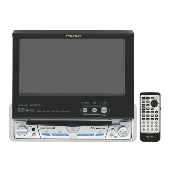
AV RECEIVER/DVD PLAYER 6.5 INCH WIDE DISPLAY
AVH-P5750DVD
AVH-P5750DVD
AVH-P5750DVD
This service manual should be used together with the following manual(s):
Model No.
Order No.
CX-3078
CRT3257
Manufactured under license from Dolby Laboratories. "Dolby" and the double-D sysmbol
are trademarks of Dolby Laboratories.
"DTS" and "DTS Digital Surround" are registered trademarks of Digital Theater Systems,
Inc.
For details, refer to "Important Check Points for Good Servicing".
PIONEER CORPORATION
PIONEER ELECTRONICS (USA) INC. P.O. Box 1760, Long Beach, CA 90801-1760, U.S.A.
PIONEER EUROPE NV Haven 1087, Keetberglaan 1, 9120 Melsele, Belgium
PIONEER ELECTRONICS ASIACENTRE PTE. LTD. 253 Alexandra Road, #04-01, Singapore 159936
PIONEER CORPORATION 2005
Mech.Module
MS-3V1
DVD Mech. Module:Circuit Description, Mech. Description, Disassembly
4-1, Meguro 1-chome, Meguro-ku, Tokyo 153-8654, Japan
AVH-P5750DVD/RC
/RD
/RI
Remarks
ORDER NO.
CRT3426
/RC
K-ZZD.MAR. 2005 Printed in Japan
Advertisement
Table of Contents

Related Manuals for Pioneer AVH-P5750DVD/RC


Summary of Contents for Pioneer AVH-P5750DVD/RC
- Page 1 PIONEER CORPORATION 4-1, Meguro 1-chome, Meguro-ku, Tokyo 153-8654, Japan PIONEER ELECTRONICS (USA) INC. P.O. Box 1760, Long Beach, CA 90801-1760, U.S.A. PIONEER EUROPE NV Haven 1087, Keetberglaan 1, 9120 Melsele, Belgium PIONEER ELECTRONICS ASIACENTRE PTE. LTD. 253 Alexandra Road, #04-01, Singapore 159936 PIONEER CORPORATION 2005 K-ZZD.MAR.
-
Page 2: Safety Information
1. During repair or tests, minimum distance of 13cm from the focus lens must be kept. 2. During repair or tests, do not view laser beam for 10 seconds or longer. 2. The triangular label is attached to the mechanism unit frame. CLASS 1 LASER PRODUCT AVH-P5750DVD/RC... - Page 3 CAUTION Danger of explosion if battery is incorrectly replaced. Replaced only with the same or equivalent type recommended by the manufacture. Discord used batteries according to the manufacture's instructions. AVH-P5750DVD/RC...
- Page 4 Under this circumstance, be careful not to contact TP781 with chassis as the power fuse of fan motor (center) will blow out, disabling the fan motor (center) to rotate. TP781 Oscilloscope Bottom of this product is a trademark of DVD Format/Logo Licensing Corporation. AVH-P5750DVD/RC...
- Page 5 To protect products from damages or failures during transit, the shipping mode should be set or the shipping screws should be installed before shipment. Please be sure to follow this method especially if it is specified in this manual. AVH-P5750DVD/RC...
-
Page 6: Table Of Contents
7.1.1 DISASSEMBLY ........................... 152 7.1.2 PCB LOCATIONS ..........................160 7.1.3 CONNECTOR FUNCTION DESCRIPTION ..................161 7.2 IC ................................162 7.3 EXPLANATION ............................187 7.3.1 MECHANISM DESCRIPTIONS ......................187 7.3.2 OPERATIONAL FLOW CHART ......................193 7.4 CLEANIG ............................... 194 8. OPERATIONS .............................. 195 AVH-P5750DVD/RC... -
Page 7: Specifications
1. SPECIFICATIONS AVH-P5750DVD/RC... - Page 8 AVH-P5750DVD/RC...
- Page 9 AVH-P5750DVD/RC...
-
Page 10: Exploded Views And Parts List
• Screw adjacent to mark on the product are used for disassembly. • For the applying amount of lobricants or glue, follow the instructions in this manual. (In the case of no amount instructions,apply as you think it appropriate.) 2.1 PACKING AVH-P5750DVD/RC... - Page 11 Fastener CNM6545 Screw(M4x3) CBA1870 Screw CMZ50P060FTC Remote Control Unit CXC3075 Polyethylene Sheet CNM4338 (2) CONTRAST TABLE AVH-P5750DVD/RC, AVH-P5750DVD/RD and AVH-P5750DVD/RI are constructed the same except for the follow- ing: Mark Description AVH-P5750DVD/RC AVH-P5750DVD/RD AVH-P5750DVD/RI Contain Box CHL5495 CHL5496 CHL5497 27-3...
-
Page 12: Exterior(1)
2.2 EXTERIOR(1) AVH-P5750DVD/RC... - Page 13 CKM1332 Socket(CN261) CKM1457 Label See Contrast table(2) Connector(CN171) CKS3751 Grille Assy CXC4189 ••••• (2) CONTRAST TABLE AVH-P5750DVD/RC, AVH-P5750DVD/RD and AVH-P5750DVD/RI are constructed the same except for the follow- ing: Mark Description AVH-P5750DVD/RC AVH-P5750DVD/RD AVH-P5750DVD/RI Mother Unit CWM9811 CWM9812 CWM9810 Label...
-
Page 14: Exterior(2)
2.3 EXTERIOR(2) AVH-P5750DVD/RC... - Page 15 190 Screw(M2x3) CBA1876 142 Rack CNV7386 191 Spring CBL1679 143 Rack CNV7387 192 Lever CND2202 144 Slider CNV7388 193 Screw CBA1797 145 Slider CNV7389 101 Screw(M2x3) CBA1082 146 Holder CNV7390 147 Arm CNV7391 148 Gear CNV7522 149 Gear CNV7523 AVH-P5750DVD/RC...
-
Page 16: Exterior(3)
2.4 EXTERIOR(3) AVH-P5750DVD/RC... - Page 17 LCD Module CWX3151 Grille Unit CXC4199 Remote Control Unit CXC3075 Cover CZN5357 Cord Assy CDE7321 Cord Assy CDE7790 Cord Assy CDE7801 CNV6727 ••••• Resistor RSV2PMF102J CNS1472 Resistor RS1/2PMF102J > 35 Fuse(10A) CEK1136 ••••• ••••• Sheet CNM9742 Spacer CNM9840 Sheet CNM9744 AVH-P5750DVD/RC...
-
Page 18: Dvd Mechanism Module(Ms3-V1)
2.5 DVD MECHANISM MODULE(MS3-V1) AVH-P5750DVD/RC... - Page 19 Lever CNV8076 105 Spring CBH2710 Lever CNV7155 CNV7156 106 Spring CBL1643 107 Spring CBH2712 Rack CNV7157 108 Pickup Unit(Service)(Screw) GXX1242 Clamper CNV7158 109 Screw Assy CXX1750 CNV7159 110 Screw(M1.4xM1.4) CBA1787 CNV7160 CNV7161 111 Cover CNC9943 112 Screw JFZ20P018FTC CNV7162 AVH-P5750DVD/RC...
-
Page 20: Block Diagram And Schematic Diagram
2.5V 3.3V SYS+B IC881 IC871 NJM2391DL1-33 NJM2388F84 3.3V REG. 8.4V REG. VOUT B.UP CONT SYS+B Q801 FU801 Q803 FU803 IC801 AN8011S D/D CONVERTER OUT1 IN-1 ON/OFF Q802 FU802 Q804 VCC15 IC831 BA00BC0WFP 3.3V REG. OUT2 IN-2 VCC33 Q806 Q805 AVH-P5750DVD/RC... - Page 21 FU803 FU771 Q773 Q771 (1/2) CONTVDB VIDEO9V REG. Q773 (2/2) VIDEO5V REG. Q892 CCONT1 Q772 Q772 VIDEO9 Q891 Q893 VIDEO5 CCONT2 Q774 FAN MOTOR CN781 (CENTER) CENTER FAN6V REG. FU781 Q782 Q781 (1/2) DDCONTL Q782 CONTB (2/2) Q783 MFLPW AVH-P5750DVD/RC...
- Page 22 GNDD CN131 ACC5 AV-BUS(V) AV− − IC581 Q691 NJM2136V Q581 VSEL1 VSELIN1 VIDEO5 VSEL2 VSELIN2 Q692 MOREM Q131 AVON AVON Q695 REMIN REMIN IC451 TA2050F Q694 FU131 AV-BUS(A) CCREM VCRINL IN2A VCRGND 10,15 OUT2 IN1B/2B VCRINR OUT1 IN1A VCRGND AVH-P5750DVD/RC...
- Page 23 MTRS LIFTPUL IC681 S-80841CNUA-B82 ANGLE B.UP B.UP RESET GEN. PWVI RESET FU701 VDD5 Q701 PWFL FU702 CN154 Q101 FU152 MFLPW Q702 (1/2) VDD5 CN952 VBILM Q755 MOTHER UNIT CILM (1/2) Q756 Q101 (2/2) VGILM Q751 CGILM Q752 CN3801 CN5501 AVH-P5750DVD/RC...
- Page 24 PNLADY MVIPW PVCC4 1.5V REG. Q4503 PVCC5 3.3V REG. PNLVD IC4183 1,2,5,6 Q4182 S-1131B15UC OUT1 -N4A PNLYV PNLADX OUT3 KDT1 VSW3V2 KDT2 OUT4 Q4502 (1/2) KDT3 OUT5 VM12 PNLXV KDT4 Q4502 (2/2) KST1 Q4501 KST2 (1/2) Q4501 (2/2) LSEN AVH-P5750DVD/RC...
- Page 25 S4392 INFO IC4183 S-1131B15UC -N4A S4393 S4394 Center Illumination (Blue) FLIP DOWN OPEN/CLOSE KDT1 KDT1 KDT1 VILLC VILLC VILLC(VILLB) VILLA VILLA VILLGB VILLGB VILLGB KDT2 KDT2 KDT2 KST1 KST1 KST1 KST2 KST2 KST2 VSW5 VACC5 IC4311 NJM062V LSEN LSEN AVH-P5750DVD/RC...
- Page 26 VOLUME UNIT CN3809 (2/2)CN175 Q3802 IC 3803 CN3843 ANGLV TA78L05F CN3842 ANGLIN0 VR3841 SNSPW CN3841 ANGLG Q3803 IC 3805 IC 3804 LIFTPUL SW UNIT GP2L24B TC7S14FU CN3807 ANGLEIN S3832 CN3833 LIFT PUSHSW LIFTSW CN3831 ANGL0SW ANGLE0 S3831 ANGLE0SW CN3832 GNDSNS AVH-P5750DVD/RC...
- Page 27 S5514 S5511 S5506 S5501 S5503 S5502 S5507 S5508 S5509 S5505 − S5513 SOURCE ANGLE BAND EJECT S5510 BOOK.M CN5501 KEY0 KEY1 KEY2 IC5501 SWVDD TSOP4840SB1 S5517 DSENS DSENS D5510,D5512,D5514 D5516,D5518,D5520 D5522,D5524,D5526 ILMG (2/2)CN101 D5502-D5508 S5516 RESET RESET D5528 DFLED AVH-P5750DVD/RC...
- Page 28 COMPOUND UNIT(A) S1201 12cm DSCSNS OSCI BECLK S1202 IC1231 Disc sens S1203 VDD33 TC7SZ125FU Disc sens S1204 CN1231 XRES_M ELERGENCY LOAD S1205 CD/DVD CLOCK GENERATOR FSSW1 IC1051 FSSW2 CLAMP SW PE5401A IC1801 IC1802 CLNP AMUT SM8707LV TC7WH157FU S1206 COMPOUND UNIT(B) AVH-P5750DVD/RC...
- Page 29 CN1551 IECOUT CN152 (2/2) Z08FU IC1652 TC7SZ126FU CN1901 IC1002 SH MEMORY R1130H501B IC1001 VCONTB S-L2980A50MC-C7J IC1003 Q1002 VCONTA VCC15 LTC3411EMS IC1851 PCM1742KE DC-DC CONVERTER ADAC Q1551 VIDEO OUT Lch OUT IC1853 CN181 (2/2) NJM2100V XRES_M IC1852 NJM2140R AMUTE,XRES_S,IRQPWR,STSCOMN,CMDCOMN VDD33 AVH-P5750DVD/RC...
-
Page 30: Overall Connection Diagram(Guide Page)
3.2 OVERALL CONNECTION DIAGRAM(GUIDE PAGE) CN1901 CN1551 C D E M DVD MECHANISM MODULE(MS3-V1) MONITOR PCB INVERTER PCB LCD MOD AVH-P5750DVD/RC... - Page 31 FAN MOTOR (REAR) FAN MOTOR (CENTER) RGB UNIT MOTHER UNIT (SYSTEM) MOTHER UNIT (POWER SUPPLY) J L K DRIVE UNIT UPPER PCB ONITOR PCB LCD MODULE AVH-P5750DVD/RC...
-
Page 32: Mother Unit(System)(Guide Page)
VIDEO FILTER FM(100%):-20.0dBs AM(30%):-30.0dBs ISOLATOR VIDEO ISOLATOR 5.0V AUDIO ISOLATOR VCR:+4.3dBs CN1551 NAVI:+4.3dBs VIDEO ISOLATOR AUDIO ISOLATOR VIDEO NAVI:+2.2dBs ISOLATOR NAVI:+2.2dBs VIDEO ISOLATOR > > CN952 IP-BUS DRIVER > IP-BUS:+2.2dBs 8 9 10 11 CN5501 1 2 3 4 AVH-P5750DVD/RC... - Page 33 The > mark found on some component parts indicates the importance of the safety factor of the part. Therefore, when replacing, be sure to use parts of identical designation. : The power supply is shown with the marked box. AVH-P5750DVD/RC...
- Page 34 VCR:+ AVH-P5750DVD/RC...
- Page 35 VCR:+8.2dBs CN954 AVH-P5750DVD/RC...
- Page 36 AVH-P5750DVD/RC...
- Page 37 AVH-P5750DVD/RC...
-
Page 38: Mother Unit(Power Supply)
3.4 MOTHER UNIT(POWER SUPPLY) FM(100%):-20.0dBs AM(30%):-30.0dBs 8.4V FMA/AM ANTENNA 5.0V 9.1V > > 3.4V > AVH-P5750DVD/RC... - Page 39 MOTHER UNIT (POWER SUPPLY) > > 8.4V FAN MOTOR (CENTER) CXM1276 M781 5.0V > 5.0V 3.4V 5.0V 5.0V 3.4V AVH-P5750DVD/RC...
-
Page 40: Monitor Pcb(Guide Page)
3.5 MONITOR PCB(GUIDE PAGE) CN5001 > CN171 CN4301 AVH-P5750DVD/RC... - Page 41 MONITOR PCB MONITOR UNIT Consists of MONITOR PCB INVERTER PCB UPPER PCB AVH-P5750DVD/RC...
- Page 42 AVH-P5750DVD/RC...
- Page 43 AVH-P5750DVD/RC...
- Page 44 AVH-P5750DVD/RC...
- Page 45 AVH-P5750DVD/RC...
-
Page 46: Dvd Core Unit(Sodc)
3.6 DVD CORE UNIT(SODC) CN152 PD6516A AVH-P5750DVD/RC... - Page 47 DVD CORE UNIT(SODC) RF SIGNAL FOCUS SERVO LINE TRACKING SERVO LINE CARRIAGE SERVO LINE SPINDLE SERVO LINE sense LOADINGMOTOR CXC4659 AVH-P5750DVD/RC...
- Page 48 AVH-P5750DVD/RC...
- Page 49 AVH-P5750DVD/RC...
- Page 50 AVH-P5750DVD/RC...
- Page 51 AVH-P5750DVD/RC...
-
Page 52: Cd Mechanism Module(Cpu)
3.7 CD MECHANISM MODULE(CPU) DVD CORE UNIT(CPU) AVH-P5750DVD/RC... - Page 53 AVH-P5750DVD/RC...
- Page 54 Interval FWD Interval REV VHALF→ VHALF→ VHALF→ 2 CH1: TD1 2 CH1: TD1 2 CH1: TD1 0.5V/div.5ms/div. 0.5V/div.5ms/div. 0.5V/div.5ms/div. 3 CH2: COP1-COM1 2.0V/div.5ms/div. 3 CH2: COP1-COM1 2.0V/div.5ms/div. 3 CH2: COP1-COM1 2.0V/div.5ms/div. Traverse501FWD Traverse501REV Traverse5000FWD VHALF→ VHALF→ VHALF→ VHALF→ VHALF→ VHALF→ AVH-P5750DVD/RC...
- Page 55 0.5V/div.20ms/div. 0.5V/div. 100µs/div. 5 FD1 0.5V/div. 1ms/div. → Play TD ID search Insaide Outside Focus close VHALF→ VHALF→ VHALF→ 5 FD1 5 FD1 5 FD1 0.5V/div.500µs/div. 0.5V/div.500µs/div. 0.5V/div.20ms/div. Focus jamp → Focus jamp → Play TD VHALF→ VHALF→ VHALF→ AVH-P5750DVD/RC...
-
Page 56: Compound Unit(A), Compound Unit(B) And Relay Pcb
3.8 COMPOUND UNIT(A), COMPOUND UNIT(B) AND RELAY PCB COMPOUND UNIT(A) Q1299 R1298 R1299 CPT231SCTD S1205 CSN1070 CN1231 DISC SENS DISC SENS S1203 CSN1069 CSN1070 S1204 S1202 CSN1069 12cm S1201 CSN1069 COMPOUND UNIT(B) RELAY PCB CLAMP CARRIAGE MOTOR CN1201 CXC4314 D E M AVH-P5750DVD/RC... -
Page 57: Pu Unit(Reference)
3.9 PU UNIT(REFERENCE) Iop78 78LD Ishf Vshf : 4V Short round 78LD 65LD LDGND 65LD Iop65 Short round LDGND 65MD Top View VR2/ 65Rmd 65MDG Im/ 2 78MD Vmda VR1/ 78Rmd 78MDG CN1101 Im/ 2 Vref : 2.5V TEMP AVH-P5750DVD/RC... -
Page 58: Inverter Pcb
3.10 INVERTER PCB > AVH-P5750DVD/RC... - Page 59 MONITOR UNIT Consists of MONITOR PCB INVERTER PCB UPPER PCB INVERTER PCB AVH-P5750DVD/RC...
-
Page 60: Rgb Unit
3.11 RGB UNIT CN154 AVH-P5750DVD/RC... - Page 61 RGB UNIT AVH-P5750DVD/RC...
-
Page 62: Upper Pcb
3.12 UPPER PCB AVH-P5750DVD/RC... - Page 63 MONITOR UNIT Consists of MONITOR PCB INVERTER PCB UPPER PCB UPPER PCB FLIP DOWN AVH-P5750DVD/RC...
-
Page 64: Keyboard Unit
3.13 KEYBOARD UNIT AVH-P5750DVD/RC... - Page 65 KEYBOARD UNIT CN101 AVH-P5750DVD/RC...
-
Page 66: Main Unit, Sw Unit And Volume Unit
3.14 MAIN UNIT, SW UNIT AND VOLUME UNIT VOLUME SW UNIT UNIT Angle sense LIFT SW ANGLE SW CN175 J K L AVH-P5750DVD/RC... - Page 67 6 CH3:ANGLSW 7 CH4:ANGLIN • OPEN -> CLOSE • Set back open -> Set 1 CH1:MTR2 2 CH2:MTRSEL 1 CH1:MTR2 8 CH2:MTRS 3 CH3:LIFTSW 4 CH4:LFTPLS 3 CH3:LIFTSW 4 CH4:LFTPLS • 0->MAX 5 CH1:MTR1 2 CH2:MTRSEL 6 CH3:ANGLSW 7 CH4:ANGLIN AVH-P5750DVD/RC...
-
Page 68: Pcb Connection Diagram
For further information for respective destinations, be sure to check with the schematic dia- gram. 2.Viewpoint of PCB diagrams Capacitor Connector SIDE A FM/AM TUNER UNIT SIDE B P.C.Board Chip Part CN954 CN1901 CN3801 CN4541 CN1551 AVH-P5750DVD/RC... - Page 69 M771 CN952 SIDE A FAN MOTOR(REAR) CORD ASSY(RCA) RCA OUT CORD ASSY(POWER SUPPLY) CORD ASSY(AV-BUS) CORD ASSY(IP-BUS) VIDEO IN AV-BUS IN IP-BUS IN M781 FAN MOTOR (CENTER) FRONT AVH-P5750DVD/RC...
- Page 70 MOTHER UNIT TP614 VCRV VCRVG AVH-P5750DVD/RC...
- Page 71 SIDE B TP190 TP803 CN5501 AVH-P5750DVD/RC...
-
Page 72: Monitor Pcb
4.2 MONITOR PCB MONITOR PCB CN171 TOUCH PANEL CN4301 FRONT AVH-P5750DVD/RC... - Page 73 SIDE A LCD MODULE CN5001 AVH-P5750DVD/RC...
- Page 74 MONITOR PCB COMDC RO4 RO3 VM12 ANG1 CSYNC ANB1 ANR1 AVH-P5750DVD/RC...
- Page 75 SIDE B CVBS1 YSIN AVH-P5750DVD/RC...
-
Page 76: Dvd Core Unit
4.3 DVD CORE UNIT DVD CORE UNIT PICKUP U ANAMONI AGND R1698 R1697 CN107 AVH-P5750DVD/RC... - Page 77 SIDE A IC,Q PICKUP UNIT(SERVICE) CN151 AVH-P5750DVD/RC...
- Page 78 DVD CORE UNIT IC,Q AVH-P5750DVD/RC...
- Page 79 SIDE B AVH-P5750DVD/RC...
-
Page 80: Compound Unit(A) , Compound Unit(B) Anp Relay Pcb
4.4 COMPOUND UNIT(A) , COMPOUND UNIT(B) ANP RELAY PCB COMPOUND UNIT(A) COMPOUND UNIT(B) Q1299 R1298 CLAMP R1299 S1205 S1204 DISC SENS S1203 DISC SENS RELAY PCB S1202 CN1201 12cm S1201 CN1231 D E M AVH-P5750DVD/RC... -
Page 81: Inverter Pcb
4.5 INVERTER PCB INVERTER PCB INVERTER PCB SIDE B SIDE A LCD MODULE GNDF2 INVPUL DIMDTY CN4521 AVH-P5750DVD/RC... -
Page 82: Rgb Unit
4.6 RGB UNIT RGB UNIT SIDE A DIGITAL OUTPUT RGB INPUT CN151 SIDE B RGB UNIT AVH-P5750DVD/RC... -
Page 83: Upper Pcb
4.7 UPPER PCB UPPER PCB UPPER PCB SIDE B SIDE A CN4591 AVH-P5750DVD/RC... -
Page 84: Keyboard Unit
4.8 KEYBOARD UNIT SIDE B KEYBOARD UNIT SIDE A KEYBOARD UNIT CN101 AVH-P5750DVD/RC... -
Page 85: Sw Unit And Volume Unit
4.9 SW UNIT AND VOLUME UNIT SW UNIT CN3807 ANGLE SW LIFT SW VOLUME UNIT ANGLE SENSE CN3809 AVH-P5750DVD/RC... -
Page 86: Main Unit
4.10 MAIN UNIT SIDE A MAIN UNIT CN3841 CN3842 CN3843 CN3831 CN3832 CN3833 CN175 AVH-P5750DVD/RC... - Page 87 SIDE B MAIN UNIT AVH-P5750DVD/RC...
-
Page 88: Electrical Parts List
PC board. IC 301 (A, 91, 111) IC NJM2068V Circuit Symbol and No. Part No. Circuit Symbol and No. Part No. Inverter PCB : NSP AVH-P5750DVD/RC Upper PCB : NSP : CWM9811 Mother Unit Keyboard Unit : NSP : CWM9822... - Page 89 Q 801 (A,27,44) Transistor 2SJ529S L 171 (A,14,63) Inductor CTF1383 Q 802 (A,53,41) Transistor 2SJ529S L 172 (A,6,55) Inductor CTF1473 Q 803 (A,33,43) Transistor 2SC4097 L 181 (A,35,79) Inductor CTF1473 Q 804 (A,48,48) Transistor 2SC4097 L 182 (A,35,81) Inductor CTF1473 AVH-P5750DVD/RC...
- Page 90 R 209 (B,136,60) RS1/16S0R0J > FU801 (A,27,27) Fuse 2.5A CEK1285 R 210 (A,148,57) RS1/16S0R0J > FU802 (A,54,22) Fuse 2.5A CEK1285 R 211 (B,130,71) RS1/16S0R0J > FU803 (A,57,59) Fuse 2.5A CEK1285 > FU861 (A,101,31) Fuse 1A CEK1280 R 212 (B,149,72) RS1/16S0R0J AVH-P5750DVD/RC...
- Page 91 R 323 (B,127,85) RS1/16S473J R 491 (B,70,127) RS1/16S0R0J R 324 (A,130,81) RS1/16S473J R 501 (B,155,8) RS1/16S0R0J R 325 (B,125,84) RS1/16S102J R 502 (B,149,28) RS1/16S272J R 401 (B,54,106) RS1/16S681J R 503 (B,127,28) RS1/16S272J R 403 (B,38,109) RS1/16S681J R 504 (B,130,13) RS1/16S272J AVH-P5750DVD/RC...
- Page 92 (A,145,38) RS1/16S750J R 664 (A,94,52) (RD,RI) RS1/16S473J R 582 (A,144,35) RS1/16S472J R 671 (A,84,53) RS1/16S103J R 583 (A,145,35) RS1/16S472J R 672 (A,88,55) RS1/16S473J R 584 (B,148,25) RS1/16S101J R 673 (A,92,55) RS1/16S473J R 585 (A,146,31) RS1/16S472J R 681 (B,98,43) RS1/16S104J AVH-P5750DVD/RC...
- Page 93 C 206 (B,147,54) CKSRYB224K16 R 814 (A,47,43) RS1/16S221J C 207 (B,137,51) CKSRYB105K6R3 R 815 (B,38,38) RS1/16S6801D C 208 (B,150,49) CKSRYB105K6R3 R 816 (A,36,37) RS1/16S1502D R 817 (A,46,35) RS1/16S6801D C 211 (B,143,51) CKSRYB105K6R3 C 212 (B,145,51) CKSRYB105K6R3 R 818 (A,47,38) RS1/16S6802D AVH-P5750DVD/RC...
- Page 94 C 313 (A,136,94) CKSRYB104K50 C 482 (B,61,64) CKSRYB102K50 C 402 (B,59,128) CKSYB475K16 C 483 (B,154,59) CKSRYB102K50 C 403 (B,59,130) CKSRYB103K50 C 484 (B,70,131) CCSRCH101J50 C 404 (A,68,110) CEVLW470M6R3 C 487 (B,48,128) CKSRYB103K50 C 405 (B,57,111) CKSRYB103K50 C 488 (B,42,65) CKSRYB104K50 AVH-P5750DVD/RC...
- Page 95 (B,106,89) CCSRCH7R0D50 C 851 (A,84,24) 0.22µF CCL1058 C 606 (B,91,64) CKSRYB105K6R3 C 852 (A,65,21) CKSQYB225K10 C 608 (B,75,61) CCSRCH101J50 C 853 (A,70,24) CKSRYB105K10 C 609 (B,74,67) CKSRYB104K50 C 854 (A,75,20) CKSRYB102K50 C 611 (B,95,56) CKSRYB103K50 C 856 (A,61,63) CKSRYB105K6R3 AVH-P5750DVD/RC...
- Page 96 (B,12,65) Transistor 2SC4617 C 981 (A,62,34) CKSYB106K6R3 Q 5003 (B,11,67) Transistor 2SC4617 C 982 (A,59,29) CKSRYB104K50 Q 5005 (B,10,72) Transistor UMX2N C 983 (A,70,38) CCSRCH150J50 Q 5342 (B,5,34) Transistor 2SA1774 C 984 (A,56,35) CKSRYB104K50 Q 5343 (A,9,52) FET SI6544DQ AVH-P5750DVD/RC...
- Page 97 L 4018 (A,114,12) Inductor CTF1306 L 4096 (A,95,17) Inductor CTF1635 L 4025 (A,119,16) Inductor CTF1306 L 4097 (A,139,44) Inductor CTF1635 L 4030 (A,121,16) Inductor CTF1306 L 4098 (A,101,38) Inductor CTF1635 L 4034 (A,125,16) Inductor CTF1306 L 4099 (A,99,18) Inductor CTF1635 AVH-P5750DVD/RC...
- Page 98 R 4005 (A,120,10) RS1/16S0R0J R 4204 (A,21,51) RS1/16S2001F R 4061 (A,138,34) RS1/16SS333J R 4216 (A,25,50) RS1/16S333J R 4062 (A,134,48) RAB4CQ221J R 4217 (A,26,56) RS1/16S102J R 4063 (A,128,50) RAB4CQ221J R 4218 (A,24,56) RS1/16S684J R 4064 (A,122,53) RAB4CQ221J R 4219 (A,23,62) RS1/16S6801F AVH-P5750DVD/RC...
- Page 99 R 4508 (A,31,77) RS1/16SS102J R 5003 (B,9,63) RS1/16S103J R 4521 (A,97,72) RS1/16SS101J R 5004 (B,11,63) RS1/16S104J R 4522 (A,96,74) RS1/16SS101J R 5005 (B,7,66) RS1/16S473J R 4523 (A,102,74) RS1/16SS101J R 5006 (B,8,70) RS1/16S621J R 4524 (A,101,74) RS1/16SS101J R 5007 (B,4,68) RS1/16S821J AVH-P5750DVD/RC...
- Page 100 (A,125,18) CKSSYF104Z16 C 4158 (A,132,52) CSZS100M16 C 4036 (A,125,12) CKSSYB104K10 C 4161 (A,130,51) CKSSYF104Z16 C 4037 (A,126,12) CKSSYB104K10 C 4162 (A,146,53) CKSRYB104K50 C 4038 (A,127,12) CKSSYB104K10 C 4163 (A,140,53) 4.7µF CCG1111 C 4039 (A,127,16) CKSSYB104K10 C 4164 (A,141,56) CKSRYB104K50 AVH-P5750DVD/RC...
- Page 101 C 5356 (B,8,54) 10µF CCG1138 C 4245 (A,75,12) CKSSYF104Z16 C 5357 (B,8,58) 10µF CCG1138 C 4248 (A,77,28) CKSSYB104K10 C 5358 (A,10,59) CKSQYB105K10 C 4261 (A,41,10) CKSRYB104K50 C 5359 (A,8,99) 22pF CCG1140 C 4301 (A,30,6) CKSRYB105K6R3 C 5361 (B,4,89) CKSRYB223K50 AVH-P5750DVD/RC...
- Page 102 RS1/16S122J IC 1231 TC7SZ125FU R 5507 (B,112,6) RS1/16S202J IC 1251 BA5985FM R 5508 (B,116,6) RS1/16S392J IC 1501 MN35104UB R 5509 (B,142,6) RS1/16S123J IC 1570 K4S283232E-TC75 R 5510 (B,156,6) RS1/16S122J IC 1601 PD6516A R 5511 (B,160,12) RS1/16S202J IC 1602 TC7SH86FU AVH-P5750DVD/RC...
- Page 103 R 1090 RAB4CQ104J EF1802 Chp EMI Filter DTL1106 R 1101 RS1/16S6R8J EF1803 Chp EMI Filter DTL1106 R 1102 RS1/16SS3R9J EF1901 Chp EMI Filter DTL1106 R 1103 RS1/16SS3R9J EF1902 Chp EMI Filter DTL1106 R 1104 RS1/16SS3R9J EF1903 Chp EMI Filter DTL1106 AVH-P5750DVD/RC...
- Page 104 R 1579 RS1/16SS220J R 1260 RS1/16SS393J R 1580 RAB4CQ560J R 1261 RS1/16SS393J R 1581 RS1/16SS560J R 1262 RS1/16SS221J R 1582 RS1/16SS560J R 1263 RS1/16S0R0J R 1583 RS1/16SS560J R 1269 RS1/16SS102J R 1584 RAB4CQ560J R 1270 RS1/16SS102J R 1585 RS1/16SS560J AVH-P5750DVD/RC...
- Page 105 C 1102 CSZSR101M6R3 R 1857 RS1/16SS102J C 1103 CKSSYB104K10 C 1104 CKSSYB103K16 R 1858 RS1/16SS222J R 1859 RS1/16SS222J C 1105 CSZSR101M6R3 R 1860 RS1/16SS472J C 1106 CKSSYB104K10 R 1861 RS1/16SS472J C 1107 CKSSYB103K16 R 1862 RS1/16SS472J C 1108 CKSRYB104K25 AVH-P5750DVD/RC...
- Page 106 C 1724 CKSSYB104K10 C 1532 CKSSYB103K16 C 1725 CKSSYB104K10 C 1533 CKSSYB103K16 C 1726 CCSSCH330J50 C 1552 CKSSYB104K10 C 1727 CKSSYB333K16 C 1553 CKSRYB104K25 C 1728 CKSSYB104K10 C 1554 CKSSYB104K10 C 1733 CKSSYB103K16 C 1555 CKSRYB105K10 C 1801 CKSSYB104K10 AVH-P5750DVD/RC...
- Page 107 BA6247FP IC 3803 TA78L05F IC 3804 TC7S14FU IC 3805 Photo-interrupter GP2L24B Unit Number:CZW3089 Q 3801 Transistor DTC124EU Unit Name:Volume Unit Q 3802 Transistor 2SA1037K Q 3803 Transistor DTC124EU VR3841(ANGLE SENSE) CCW1025 Q 3804 Transistor UMD2N D 3801 Diode UDZS5R6(B) AVH-P5750DVD/RC...
- Page 108 Circuit Symbol and No. Part No. Miscellaneous Parts List Pickup Unit(Service) CXX1770 Motor Unit(LOADING) CXC4659 Motor Unit(CARRIAGE) CXC4134 Motor(SPINDLE) CXM1272 M 771 Fan Motor(REAR) CXM1262 M 781 Fan Motor(CENTER) CXM1276 M 3001 Motor Unit(POSITION) CXB9515 M 3002 Motor Unit(ANGLE) CXB9516 AVH-P5750DVD/RC...
-
Page 109: Adjustment
Connecting the mother unit to relay PCB(GGF1461) 40 pin extension cable GGD1170 Connecting the mother unit to relay PCB(GGF1461) 40 pin extension cable GGD1284 Connecting the mother unit to DVD mechanism module 2 pin extension cable GGD1439 Connecting the mother unit to DVD mechanism module AVH-P5750DVD/RC... -
Page 110: Dvd Adjustment
Attention) • Test mode starting procedure Reset start while pressing the BAND and ANGLE- keys together. • Test mode stopping procedure ACC and Backup OFF. AVH-P5750DVD/RC... - Page 111 Focus Gain Coefficient(Layer1) CD x 4CLV: Tracking Gain Coefficient(Layer0) 4X00 0000 Tracking Gain Coefficient(Layer1) Track number RIGHT AS normalization adjustment feature specification specification ANGLE+ (Layer0) AS normalization adjustment feature ID display Track (Layer1) number display Jump start Search Start AVH-P5750DVD/RC...
- Page 112 Please confirm the disc 0X9A AV chip error DVD is stopping because mechanism detected abnormality 0X9B RecaveryNG(BE) DVD is stopping because mechanism detected abnormality Play state error 0X9C 0X9D Disc data error 0X9E Serface error (Disc distinction is improper) AVH-P5750DVD/RC...
- Page 113 Measurement device and tools : Oscilloscope Allen key wrench 40-pin flexible extension (GGD1284) 2-pin extension cable(GGD1439) Disk used Screw lock (GYL1001) Measurement reference : GGV1018 Measurement point : AGND3 Connection diagram : ANAMONI DVD core unit ANAMONI Oscilloscope AGND AVH-P5750DVD/RC...
- Page 114 10. Adjust with a screw rock the shaft and skew adjustment screw to the same state as initial one. Skew adj. screw Skew adj. screw Apply glue Prevent applied glue Prevent applied glue Shaft from extending beyond this position. from extending beyond this position. AVH-P5750DVD/RC...
- Page 115 Execute Check 2 Is the audio circuit operating normally? Execute Check Is the video circuit operating normally? Execute Check Is SDRAM I/F Repair or replace operating normally? any defective unit Execute Check 5 All checks normal? Check completed AVH-P5750DVD/RC...
- Page 116 0.8V 33.8688MHz 300ppm MCK33 2.2V VCC33 0.8V 33.898MHz 300ppm IC1501 92pin DACCLK IC1851 16pin 2.0V VCC33 0.8V 33.8688MHz 300ppm DACCLK 2.3V VCC33 0.99V 33.8689MHz 300ppm IC1881 3pin Rated Value 1 Rated value 3 Rated Value 2 Clock rated values AVH-P5750DVD/RC...
- Page 117 Circuit Diagram AVH-P5750DVD/RC...
- Page 118 These resistors are inserted. GNDAU LO and RO output measurement circuit Verification location 1 Verification location 2 Rated value 1 Rated value 2 Reference waveform (Sensing pin) VCC33V - 0.6V and over IEC958 CN1551 1pin 0.4Vand lower Waveform 3 AVH-P5750DVD/RC...
- Page 119 Circuit Diagram AVH-P5750DVD/RC...
- Page 120 214pin IC1570 60pin IC1501 210pin IC1501 212pin IC1570 61pin IC1570 62pin IC1501 216pin IC1570 63pin IC1501 219pin IC1570 64pin IC1501 227pin IC1570 65pin IC1501 229pin IC1570 66pin IC1501 235pin MA10 IC1570 24pin IC1501 228pin MA11 IC1570 21pin IC1501 231pin AVH-P5750DVD/RC...
- Page 121 242pin XRAS IC1570 19pin IC1501 239pin XCSM IC1570 20pin IC1501 238pin DQM0 IC1570 16pin IC1501 243pin DQM1 IC1570 71pin 246pin IC1501 DQM2 IC1570 28pin IC1501 208pin DQM3 IC1570 59pin IC1501 207pin IC1570 22pin IC1501 234pin IC1570 23pin IC1501 237pin AVH-P5750DVD/RC...
- Page 122 Circuit Diagram AVH-P5750DVD/RC...
- Page 123 CH1: IEC958 1V/div. 500ns/div. CH1: AOUT0 CH1: LO 1V/div. 500µs/div. CH2: SRCKAV CH2: RO 2V/div. 2µs/div. CH3: LRCKAV ←T G→ ←T G→ G→ G→ G→ ←T G→ Waveform3 Waveform1 Waveform2 CH1: COMPO 200mV/div. 10µs/div. [White 100% output] G→ Waveform4 AVH-P5750DVD/RC...
-
Page 124: Mother Unit Adjustment
6.3 MOTHER UNIT ADJUSTMENT - Adjustment Point SIDE A VR801 VR511 SIDE B TP614 TP190 TP803 VCRV VCRVG AVH-P5750DVD/RC... - Page 125 AVH-P5750DVD/RC...
-
Page 126: Monitor Pcb Adjustment
6.4 MONITOR PCB ADJUSTMENT - Adjustment Point SIDE B CVBS1 YSIN COMDC GO04 VM12 ANG1 CSYNC ANB1 ANR1 AVH-P5750DVD/RC... - Page 127 AVH-P5750DVD/RC...
- Page 128 AVH-P5750DVD/RC...
- Page 129 AVH-P5750DVD/RC...
-
Page 130: Inverter Pcb Adjustment
6.5 INVERTER PCB ADJUSTMENT - Adjustment Point SIDE A SIDE B GNDF2 VR5341 INVPUL DIMDTY VPFL1 AVH-P5750DVD/RC... - Page 131 AVH-P5750DVD/RC...
-
Page 132: Monitor Test Mode
After changing the value of CS (CHECKSUM), take exclusive OR (XOR) with 8-bit and execute writing. After writing this CS value to EEPROM, read and display it, too. If the written value and the read value are different, change the color of the read value. AVH-P5750DVD/RC... - Page 133 Touch panel X coordinate 6 Touch panel Y coordinate 6 Touch panel X coordinate 7 Touch panel Y coordinate 7 Touch panel X coordinate 8 Touch panel Y coordinate 8 Touch panel X coordinate 9 Touch panel Y coordinate 9 AVH-P5750DVD/RC...
- Page 134 A : Microcomputer writes the result whether flicker adjustment is performed or not (direct mode, EEPROM adjustment screen). B : Production engineering jig: After completing EEPROM adjustment, the value is written (this value is displayed on the confirmation screen). AVH-P5750DVD/RC...
- Page 135 Note2 : Be careful about the contents of [R, G, B OUT BIAS] and [RGB, CMP CONTRST] since their indicated value / EEPROM written value and their registered value of 2-display IC (TC90A96AFG) are different. (Software conversion is running because correlation between registered value of 2-display IC and display output is not linear.) AVH-P5750DVD/RC...
- Page 136 (Software conversion is running because correlation between registered value of 2-display IC and display output is not linear.) Indicated value EEPROM written Registered value of (=adjustment value) value (DEC) 2- display IC (BIN) (DEC) ( MAX ) 0111 0110 0001 ( TYP ) 0000 1111 1001 ( MIN ) 1000 AVH-P5750DVD/RC...
- Page 137 MH LIMIT Main horizontal enhancer f0 (SA10 [D8]) [0-1] MH F0 Main vertical enhancer gain (SA10 [D7-6]) [0-3] MV GAIN Main vertical enhancer replicable (SA10 [D5-4]) [0-3] MV ORI Main vertical enhancer coring (SA10 [D3-2]) [0-3] MV CORE FFFF AVH-P5750DVD/RC...
- Page 138 (Software conversion is running because correlation between registered value of 2-display IC and display output is not linear.) [BRIGHTNESS R, G, B] Indicated value EEPROM written Registered value of (=adjustment value) value (DEC) 2- display IC (BIN) (DEC) ( MAX ) 011111 011110 000001 ( TYP ) 000000 111111 100001 ( MIN ) 100000 AVH-P5750DVD/RC...
- Page 139 SA46H UPPER LINE9 SA46[D7-D0] [0-255] SA46H LOWER SA47[D15-8] [0-255] SA47H UPPER SA47[D7-D0] [0-255] SA47H LOWER SA48[D15-8] [0-255] SA48H UPPER SA48[D7-D0] [0-255] SA48H LOWER SA49[D15-D8] [0-255] SA49H UPPER SA49[D7-D0] [0-255] SA49H LOWER SA4A[D15-8] [0-255] SA4AH UPPER SA4A[D7-D0] [0-255] SA4AH LOWER FFFF AVH-P5750DVD/RC...
- Page 140 Ultimate perimeter (Xmin) of touch panel Ultimate perimeter (Xmax) of touch panel Ultimate perimeter (Ymin) of touch panel Ultimate perimeter (Ymax) of touch panel Result of adjusting calibration of touch panel Result of adjusting ultimate perimeter of touch panel AVH-P5750DVD/RC...
- Page 141 BRIGHT_B GAMMA_1 GAMMA_2 GAMMA_3 GAMMASLP_A GAMMASLP_B GAMMASLP_C SA24H_UPPER SA24H_LOWER SA25H_UPPER SA25H_LOWER SA26H_UPPER_TV SA26H_LOWER_TV SA26H_UPPER SA26H_LOWER SA27H_UPPER_TV SA27H_LOWER_TV SA27H_UPPER SA27H_LOWER SA46H_UPPER SA46H_LOWER SA47H_UPPER SA47H_LOWER SA48H_UPPER SA48H_LOWER SA49H_UPPER SA49H_LOWER SA4AH_UPPER SA4AH_LOWER SA4BH_UPPER SA4BH_LOWER SA4CH_UPPER SA4CH_LOWER SA4DH_UPPER SA4DH_LOWER SA4EH_UPPER SA4EH_LOWER SA4FH_UPPER SA4FH_LOWER AVH-P5750DVD/RC...
-
Page 142: Touch Panel Test Mode
No calibration is done after product completion. Adjusted value initialization is done. EEPROM initialization is done. Confirmation indication of conditioned EEPROM Newly available with this product See “Production engineering test : result feedback specification document ” for more detail. AVH-P5750DVD/RC... - Page 143 0 1 2 3 4 5 6 7 8 9 0 1 2 3 4 5 6 7 8 9 0 1 2 3 4 5 6 7 8 9 N . G [ E N T E R ] R e t u r n M e n u NG condition information AVH-P5750DVD/RC...
- Page 144 Consider diameter of the top of jig (pen tip) before adjusting outermost circumference. Out-of-alignment length pen tip for adjustment (zoom in) Perform calibration data operation with the size calculated by subtracting out-of-alignment length from permissible screen area. out-of-alignment length permissible screen area AVH-P5750DVD/RC...
- Page 145 3.3 Processing detail The taken setting value is stored in EEPROM only when pressing the 17th point, and [ FINISHED ] is displayed after storing. See “ t ” about the area for storing EEPROM settings. See “ ” See “ AVH-P5750DVD/RC...
- Page 146 Rounding was done within the setting range with outermost circumference adjustment in the conventional product (AVH-P9DVA). When value more than outermost circumference value was entered, the outermost circumference value was used. From this time, considering that audit may be performed without outermost circumference adjustment, no limit is set. AVH-P5750DVD/RC...
- Page 147 According to the length between + indication and touched coordinates (the point where the cursor is pointed), OK or NG is indicated. the length between + position and cursor indication is within ± 6 mm at the center OK condition NG condition except OK condition AVH-P5750DVD/RC...
- Page 148 Add the correction value at the left corner first. Then, the effect of correction value is increasing as going to right. Coordinates after data ∼ Right corner correction Left corner correction data Left corner coordinates of ∼ data of correction area of correction area correction area ∼ AVH-P5750DVD/RC...
- Page 149 Press [ ENT ] key of main unit or remote control unit to return to TOP MENU. 6.3 Processing detail [ Initialization processing ] It initializes outermost circumference value and 16-point value. It writes default of initialized items to EEPROM and clears conditioned flag. AVH-P5750DVD/RC...
- Page 150 Outermost circumference permissible error value 10 % Voltage (V) 0.25 digital (AD) dot (OSD) NAVI Voltage (V) 0.23 digital (AD) dot (OSD) NAVI Outermost circumference adjustment OK zone Minimum permissible value Maximum permissible value Minimum permissible value Maximum permissible value AVH-P5750DVD/RC...
- Page 151 Permissible error of point calibration should be 10 % 10 % 10 % Settings valid zone (OK) Settings invalid zone (NG) Outermost circumference permissible error value 10 % Voltage (V) 0.25 digital (AD) dot (OSD) NAVI Voltage (V) 0.23 digital (AD) dot (OSD) NAVI 3.3 (V) AVH-P5750DVD/RC...
-
Page 152: General Information
Be very careful and do not give it a strong pull when removing the Case, otherwise it may Case Holder Grille Assy be torn. Fig.1 Removing the DVD Mechanism Module (Fig.2) Remove the four screws. Disconnect the connector and then remove the DVD Mechanism Module. DVD Mechanism Module Fig.2 AVH-P5750DVD/RC... - Page 153 Disconnect the connector and then remove the Fan Motor. Remove the two screws. Remove the five screws and then remove the Panel. Straighten the tabs at five locations indicated. Remove the screw and then remove the Mother Unit. Mother Unit Fan Motor Holder Fig.3 AVH-P5750DVD/RC...
- Page 154 Removing the Main Unit (Fig.6) Bracket Remove the screw and then remove the Bracket. Remove the four screws and then remove the Shaft Unit. Remove the three screws. Disconnect the connector and then remove the Main Unit. Main Unit Fig.6 AVH-P5750DVD/RC...
- Page 155 Disconnect the connector and then remove the Monitor PCB. Monitor PCB Fig.8 Note: Tighten the screws with the panel in warped state as shown in the photograph below. Otherwise, it will be difficult to install Detach Grille Assy to Panel Assy. AVH-P5750DVD/RC...
- Page 156 Make sure that the flexible PCB and the sheet contact a bracket. In addition, since adhesive strength becomes weak, do not use again the sheet removed once. Sheet (CNM9517) Flexible PCB (CNP8806) Bracket (CND2627) AVH-P5750DVD/RC...
- Page 157 B to remove it. Be careful not to damage the flexible cable C. 7. Disconnect the 8/12 detection flexible-cable from the connector. Short here. Module pc board Connector (for pickup flexible cable) Connector (for 8/12 detection flexible cable) Load motor leads and clamp SW leads Connector (for CRG flexible cable) AVH-P5750DVD/RC...
- Page 158 Do not reuse the old skew screw. Be sure to use a brand-new skew screw supplied with a new pickup unit. Fix the skew screw with glue (GYL1001) after adjustment. Skew screw (main) Skew screw Pickup unit Sub shaft Skew screw AVH-P5750DVD/RC...
- Page 159 1. Set the Monitor Unit horizontally with the Main Unit of the Drive Unit. 2. When install the gear unit, rotate the gear by hand until the square box of the gear keeps in a horizontal position like the figure below. Square box *Gap of one teeth is acceptable. AVH-P5750DVD/RC...
-
Page 160: Pcb Locations
7.1.2 PCB LOCATIONS SW UNIT MAIN UNIT INVERTER PCB RGB UNIT MONITOR PCB VOLUME UNIT UPPER PCB KEYBOARD UNIT MOTHER UNIT RELAY PCB DVD CORE UNIT COMPOUND(A) COMPOUND(B) AVH-P5750DVD/RC... -
Page 161: Connector Function Description
15 : REAUR 16 : GND 16 : REAUL 17 : GNDRAU 18 : CCREM 19 : DSEN 20 : TVON 21 : GION 22 : MONON 23 : VSW5 24 : HTXD 25 : HRXD 26 : GNDD AVH-P5750DVD/RC... - Page 162 IC's marked by * are MOS type. Be careful in handling them because they are very liable to be damaged by electrostatic induction. 1 IN B 5 VCC 2 IN A 3 GND 4 OUT Y *NJM2136V *S-818A35AUC-BGP ON/OFF -INPUT +INPUT ONTPUT ON/OFF VOUT AVH-P5750DVD/RC...
- Page 163 Over Voltage Thermal Over Current Protection Protection Protection CONT *TC74VHC08FTS1 14 VCC 1 1A 13 4B 2 1B 12 4A 3 1Y 4 2A 11 4Y 10 3B 5 2B 9 3A 6 2Y 7 GND 8 3Y AVH-P5750DVD/RC...
- Page 164 Not used RCAMUTE RCA REAR mute output 51,52 VSELIN1,2 VSEL input AVONIN AV-BUS AV video sense input 54,55 Not used TESTIN Test mode input Not used PRGON System microcomputer program mode input VPPON VPP ON/OFF output PORTVDD1 Port power supply AVH-P5750DVD/RC...
- Page 165 RGB navigation ON sense input Not used NMIXCNT Voice guide mute output MUTE Mute output Not used AMPMUTE AMP mute output 125,126 Not used TELIN TEL mute input VDD1 Power supply PBSENS Packing brake sense input BGSENS Back gear sense input AVH-P5750DVD/RC...
- Page 166 Pin Name Function and operation GND1 132-134 Not used TUNSL TUNER signal level input Not used ANGLEIN Mechanism volume for angle sense input 138,139 Not used 140-142 KEYDTA0-2 Key data input0-2 ADCVDD A/D Power supply ADCGND A/D GND *PE5485A AVH-P5750DVD/RC...
- Page 167 D-RGB H/C.Sync IN D-RGB H/C.Sync IN OSD H/C.Sync Out OSD H/C.Sync Out D-RGB Clock IN D-RGB Clock IN OSD V.Sync Out OSD V.Sync Out OSD Clock Out OSD Clock Out Test(DTNB) Test(DTNB) VDD-D5 VDD-D5 VDD-D7 VDD-D7 VSS-D5 VSS-D5 VSS-D7 VSS-D7 AVH-P5750DVD/RC...
- Page 168 TC90A96AFG - Block Diagram AVH-P5750DVD/RC...
- Page 169 TC7SET04FUS1 *TC74VHC04FTS1 BD6171KV - Pin Layout AVH-P5750DVD/RC...
- Page 170 0.6V VO1DET SOFT INVERT START ERROR AMP PVCC2 DRIVER LATCH OUT2 INV2 RESET VREGA OCPC2 0.6V VO2DET SYNC UVLO DELAY OSCILLATOR PVCC5 PVCC4 OUT5 OUT4 5VREG DVCC VREGA VREGA VREF 0.6V 0.6V PGND5 PGND4 SGND DGND VO5DET VREGA VO4DET AVH-P5750DVD/RC...
- Page 171 Protector IN A ON/OFF OUT Y VOUT *TC7SH32FUS1 *S-93C56BD0I-J8 1 IN B 5 VCC :Not used :Power supply :Chip select input :Clock input :Data input 2 IN A TEST :Data output :Ground TEST :Test 3 GND 4 OUT Y AVH-P5750DVD/RC...
- Page 172 I=3uA NDR_B CTIMR NDR_B I=6uA Protection PDR_A PDR_A hys. Soft COMP Start POFF ACTIVE hys. "HIGH" COMP SST2 POFF VCCA Reference VCCA PGND sub. GNDA Burst- Mode OPLAMP 2.50V Control Phase-Shift Controller LPWM PDR_C PDR_C SST/2.5 1.25V NDR_D NDR_D AVH-P5750DVD/RC...
- Page 173 54-61 Not used HSYNC HSYNC signal input for OSD Not used VSYNC VSYNC signal input for OSD 65,66 Not used 67,68 KS2,1 Key strobe input/output 69-72 KD4-1 Key data input 73,74 Not used STEST2 Touch panel test mode input AVH-P5750DVD/RC...
- Page 174 Touch panel:sense output PNLADY Touch panel:X data input PNLADX Touch panel:Y data input LSEN Brightness on the outside sense input VHOLD2 Not used HLF2 Not used CVIN2 Not used TVSETB Test mode input VCCE Power supply CVIN1 Not used *PEG087A AVH-P5750DVD/RC...
- Page 175 1M x 32 1M x 32 Column Decoder Latency & Burst Length A10/AP LCKE Programming Register LRAS LCBR LCAS LWCBR DQM2 DQM3 Timing Register DQ16 DQ31 DQ17 DQ30 DQ18 DQ29 DQ16 DQ28 DQ20 DQ27 DQ21 DQ26 DQ22 DQ25 DQ23 DQ24 AVH-P5750DVD/RC...
- Page 176 Divider 0 Divider 0 Pump 0 X’tal VSS1 SO4,SO3,SO2,NC1 Loop MO1,NC1 FSEL,NC2 Divider 0 MO2,NC1,SO1 SO3,SO2,SO1 Control Logic Reference Phase Charge LPF 1 VCO 1 Divider 1 Divider 1 Pump 1 VDD2 VDD3 VSS2 VSS3 Loop Divider 1 AO1,SO2 SO2,SO1,AO1 AVH-P5750DVD/RC...
- Page 177 *TC74LCX16373AFT AVH-P5750DVD/RC...
- Page 178 52 51 50 49 48 47 46 45 44 43 42 41 40 P75/KR5 P76/KR6 P77/KR7 PP/IC P00/TI000 REGC P01/TI010/TO00 P10/sck10/R reset P11/SI10/R P12/SO10 P13/T P130 P14/R P120/INTP0 14 15 16 17 18 19 20 21 22 23 24 25 26 AVH-P5750DVD/RC...
- Page 179 DQ14 DQ13 DQ12 :Data output/Address input ON/OFF A0-A20 :Address input DQ0-D15 :Data input output byte :Mode select reset :Chip enable input VOLTAGE :Output enable input REFERENCE RY/by :Ready/Busy output DQ11 reset :Reset :Acc :Power supply :GND DQ10 RY/by ON/OFF AVH-P5750DVD/RC...
- Page 180 *LTC3411EMS SHDN/R PMOS CURRENT COMPARATOR 0.8V VOLTAGE VOLTAGE REFERENCE REFERENCE SYNC/MODE ERROR BURST AMPLIFIER COMPARATOR 0.74V SLOPE COMPENSATION OSCILLATOR SGND PGOOD 0.86V LOGIC NMOS COMPARATOR REVERSE PGND COMPARATOR *TC7SZ125FU *MN35104UB IN A OUT Y AVH-P5750DVD/RC...
- Page 181 Serial output data I / O Serial input data I / O Serial clock I / O Serial output data I / O Serial input data VDD3 IO power supply MMOD Test mode setting I / O Serial clock AVH-P5750DVD/RC...
- Page 182 Inside monitor AVDDD Power supply PLFIL1 DRC VCO AVSSD PLFIL2 DRC VCO 108-110 VREF Reference voltage gm-cEQ RESI gm-cEQ ANAMONI Inside analog monitor POFLT DPDOFTR CDATA Inline data CCAPA Inline capacitor Reference voltage AVDDC Analog current AVSSC Analog GND AVH-P5750DVD/RC...
- Page 183 DAC3OUT Analog signal VREF Reference voltage DAC4OUT Analog signal DAC5OUT Analog signal AVDDG Analog power suplly IREF2 Inside DAC bias current VSSG Analog GND COMP2 Inside DAC BECLK Backend clock input VDD33 IO power supply EXTCK Exterior audio clock AVH-P5750DVD/RC...
- Page 184 Power supply SDRAM address SDRAM address VDD15 Power supply SDRAM address 216,217 SDRAM address VDD33 Power supply 219,220 SDRAM address VDD15 Power supply MCKI SDRAM output clock SDRAM input clock VDD33 IO power supply 227-229 SDRAM address SDRAM address AVH-P5750DVD/RC...
- Page 185 SDRAM column address strobe DQM0 SDRAM data mask VDD15 Power supply SDRAM data mask I / O SDRAM data I / O SDRAM data VDD33 IO power supply 251-253 I / O SDRAM data 255,256 I / O SDRAM data AVH-P5750DVD/RC...
- Page 186 22 AUDIOGND audio ground Ground of audio block 23 L ch O L channel output FM stereo “L-ch” signal output or AM audio output 24 R ch O R channel output FM stereo “R-ch” signal output or AM audio output AVH-P5750DVD/RC...
-
Page 187: Explanation
3. For a period of 600ms from the time when LIFTSW is switched from H to L, the forward/backward driving motor keeps rotating in the ejection direction. 4. After 600ms, the forward/backward driving motor is stopped, and the angle driving motor rotates in the UP direction. AVH-P5750DVD/RC... - Page 188 600ms from the time when LIFTSW is switched from H to L, then the angle driving motor is rotated in the 0° direction. AVH-P5750DVD/RC...
- Page 189 LIFTSW has switched from H to L. When 3 seconds have elapsed from the time of angle adjustment completion, the forward/backward driving motor is rotated in slow speed in the horizontal storage direction, and brake is applied when LIFTSW has switched from L to H. AVH-P5750DVD/RC...
- Page 190 It should be noted, however, that the last memory will not be stored when the monitor is manually moved by force. 2. If the expected pulse is not detected during horizontal motion, the monitor will stop at that position. AVH-P5750DVD/RC...
- Page 191 * When the setback is being set to OFF, there will be no advance/return motion. After ACC OFF, if ACC is switched ON again during the 6 seconds counting, standby will be passed and the FLAP status will not change. AVH-P5750DVD/RC...
- Page 192 Return ACC OFF OPEN motion Continue OPEN motion OPEN motion Last angle Last angle Last angle Return Return Return Last memory OPEN OPEN OPEN * When the setback is being set to OFF, there will be no advance/return motion. AVH-P5750DVD/RC...
-
Page 193: Operational Flow Chart
System with Display microcomputer microcomputer. Resending dimand Response Connection Source keys formation SYS resending operative dimand Source ON Comunication formation SYSPW←H Display processing Pin 31 Completes power-on operation. (After that, proceed to each source operation) AVH-P5750DVD/RC... -
Page 194: Cleanig
Before shipping out the product, be sure to clean the following portions by using the prescribed cleaning tools: Portions to be cleaned Cleaning tools DVD pickup lenses Cleaning liquid : GEM1004 Cleaning paper : GED-008 Portions to be cleaned Cleaning tools Cleaning paper : GED-008 Fans AVH-P5750DVD/RC... -
Page 195: Operations
8. OPERATIONS AVH-P5750DVD/RC... - Page 196 AVH-P5750DVD/RC...
- Page 197 AVH-P5750DVD/RC...
- Page 198 AVH-P5750DVD/RC...
- Page 199 AVH-P5750DVD/RC...
- Page 200 AVH-P5750DVD/RC...
- Page 201 AVH-P5750DVD/RC...
- Page 202 AVH-P5750DVD/RC...
- Page 203 AVH-P5750DVD/RC...
- Page 204 AVH-P5750DVD/RC...
- Page 205 AVH-P5750DVD/RC...
- Page 206 AVH-P5750DVD/RC...
- Page 207 AVH-P5750DVD/RC...
- Page 208 AVH-P5750DVD/RC...
- Page 209 AVH-P5750DVD/RC...
- Page 210 AVH-P5750DVD/RC...
- Page 211 AVH-P5750DVD/RC...
- Page 212 Connecting the mother unit to relay PCB(GGF1461) 40 pin extension cable GGD1170 Connecting the mother unit to relay PCB(GGF1461) 40 pin extension cable GGD1284 Connecting the mother unit to DVD mechanism module 2 pin extension cable GGD1439 Connecting the mother unit to DVD mechanism module AVH-P5750DVD/RC...