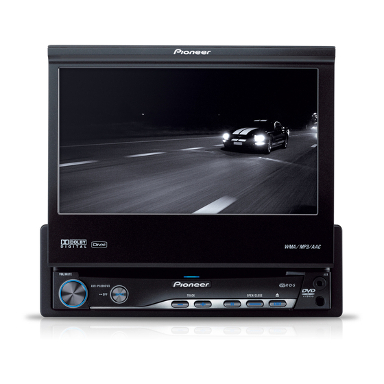
Pioneer AVH-P5000DVD Installation Manual
Pioneer avh-p5000dvd: install guide
Hide thumbs
Also See for AVH-P5000DVD:
- Operation manual (118 pages) ,
- Installation manual (8 pages) ,
- Service manual (202 pages)
Table of Contents
Advertisement
Available languages
Available languages
Quick Links
AVH-P5000DVD
Printed in Thailand
Imprimé en Thaïlande
<CRD4275-A/N> UC
<KMINX> <07K00000>
Connecting the Units
WARNING
CAUTION
• To avoid the risk of accident and the potential vio-
lation of applicable laws, the front DVD or TV
• PIONEER does not recommend that you
(sold separately) feature should never be used
install or service your display yourself.
while the vehicle is being driven. Also, Rear
Installing or servicing the product may
Displays should not be in a location where it is a
expose you to risk of electric shock or
visible distraction to the driver.
other hazards. Refer all installation and
• In some countries or states the viewing of
images on a display inside a vehicle even by
servicing of your display to authorized
persons other than the driver may be illegal.
Pioneer service personnel.
Where such regulations apply, they must be
• Secure all wiring with cable clamps or
obeyed and this unit's DVD features should
not be used.
electrical tape. Do not allow any bare
wiring to remain exposed.
• Do not drill a hole into the engine com-
partment to connect the yellow lead of
the unit to the vehicle battery. Engine
vibration may eventually cause the insu-
lation to fail at the point where the wire
passes from the passenger compartment
into the engine compartment. Take extra
care in securing the wire at this point.
• It is extremely dangerous to allow the
display lead to become wound around
the steering column or gearshift. Be sure
to install the display in such a way that it
will not obstruct driving.
• Make sure that wires will not interfere
with moving parts of the vehicle, such as
the gearshift, parking brake or seat slid-
ing mechanism.
• Do not shorten any leads. If you do, the
protection circuit may fail to work prop-
erly.
WARNING
LIGHT GREEN LEAD AT POWER CONNEC-
TOR IS DESIGNED TO DETECT PARKED
STATUS AND MUST BE CONNECTED TO
THE POWER SUPPLY SIDE OF THE PARK-
ING BRAKE SWITCH. IMPROPER CONNEC-
TION OR USE OF THIS LEAD MAY VIOLATE
APPLICABLE LAW AND MAY RESULT IN
SERIOUS INJURY OR DAMAGE.
Note:
•
Control signal is output through blue/white cable
•
This unit cannot be installed in a vehicle with-
when this unit is powered on. Connect it to an
out ACC (accessory) position on the ignition
external power amp's system remote control or
switch.
the vehicle's auto-antenna relay control terminal
(max. 300 mA, 12 V DC). If the vehicle is
equipped with a glass antenna, connect it to the
antenna booster power supply terminal.
•
Never connect blue/white cable to external power
amp's power terminal. Also, never connect it to
the power terminal of the auto antenna.
Otherwise, battery drain or malfunction may
result.
•
IP-BUS connectors are color-coded. Be sure to
ACC position
No ACC position
connect connectors of the same color.
•
Use this unit in other than the following condi-
•
Black cable is ground. This cable and other prod-
tions could result in fire or malfunction.
uct's ground cable (especially, high-current prod-
— Vehicles with a 12-volt battery and negative
ucts such as power amp) must be wired separate-
grounding.
ly. Otherwise, fire or malfunction may result if
— Speakers with 50 W (output value) and 4 ohm
they are accidentally detached.
to 8 ohm (impedance value).
•
To prevent short-circuit, overheating or malfunc-
tion, be sure to follow the directions below.
— Disconnect the negative terminal of the battery
before installation.
— Secure the wiring with cable clamps or adhe-
sive tape. To protect the wiring, wrap adhesive
tape around them where they lie against metal
parts.
— Place all cables away from moving parts, such
as gear shift and seat rails.
— Place all cables away from hot places, such as
near the heater outlet.
— Do not pass the yellow cable through a hole
into the engine compartment to connect to a
battery.
— Cover any disconnected cable connectors with
insulating tape.
— Do not remove RCA caps if RCA cables are
not used.
— Do not shorten any cables.
— Never cut the insulation of the power cable of
this unit in order to share the power to other
equipment. Current capacity of the cable is
limited.
— Use a fuse of the rating prescribed.
— Never wire the speaker negative cable directly
to ground.
— Never band together multiple speaker's nega-
tive cables.
ENGLISH
Parts supplied
This product
Tuner box
Power cord
Antenna cable
Mounting sleeve
Trim ring
Side bracket (small)
USB cable
(pre-installed)
(pre-installed)
(2 pcs.) (pre-installed)
Flush surface screw
Binding screw
Binding screw
Screw (2 mm × 3 mm)
(5 mm × 6 mm) (6 pcs.)
(5 mm × 6 mm)
(4 mm × 3 mm)
(4 pcs.) (pre-installed)
(2 are pre-installed.)
(4 pcs.)
(4 pcs.)
Side bracket (large)
Concealing tape
Rubber bush
Double-ended screw
(2 pcs.)
Screw (2 mm × 5 mm)
Touch panel pen
Holder
(2 pcs.)
Advertisement
Table of Contents

Related Manuals for Pioneer AVH-P5000DVD


Summary of Contents for Pioneer AVH-P5000DVD
-
Page 1: Connecting Units
Connecting the Units CAUTION • PIONEER does not recommend that you install or service your display yourself. Installing or servicing the product may expose you to risk of electric shock or other hazards. Refer all installation and servicing of your display to authorized Pioneer service personnel. -
Page 2: Connecting Power Cord
Connecting the Units Connecting the power cord Wired remote input Hard-wired remote control adaptor Gray can be connected (sold separately). 1.5 m (4 ft. 11 in.) USB cable (supplied) 20 cm (7-7/8 in.) Connect to separately sold IP-BUS input USB input USB device. -
Page 3: External Video Component/Display
Connecting the Units When connecting with a rear view camera When connecting with a multi-channel processor When this product is used with a rear view camera, it is possible to automatically switch from the video to rear view image when the gear shift is moved to REVERSE (R). WARNING USE INPUT ONLY FOR REVERSE OR MIRROR IMAGE REAR VIEW CAMERA. -
Page 4: Installation
Installation Note: • Make sure you leave enough gap between the Before installing the unit dashboard and the LCD panel of this unit so the • Check all connections and systems before final installation. LCD panel can be opened and closed without •... -
Page 5: Pièces Fournies
• Pour éviter tout risque d’accident, et toute infrac- véhicule dont le contacteur d’allumage ne pos- tion aux lois en vigueur, l’affichage à l’avant d’im- • PIONEER ne vous recommande pas sède pas de position ACC (accessoire). age de DVD ou de télévision (vendue séparément) d’installer ou d’entretenir vous-même... -
Page 6: Raccordements Des Appareils
Raccordements des appareils Branchement du cordon d’alimentation Entrée pour télécommande câblée Un adaptateur de télécommande câblée peut être connecté à cette prise (vendu séparément). Gris 1,5 m Câble USB (fourni) 20 cm Connectez-le à un Entrée IP-BUS Entrée USB périphérique USB vendu (Bleu) séparément. - Page 7 Raccordements des appareils Raccordements à une caméra de recul Lors du raccordement d’un processeur multi-canaux Quand cet appareil est utilisé avec une caméra de recul, il est possible de commuter automatiquement sur l’image de la caméra de recul quand le sélecteur de vitesse est placé sur REVERSE (R).
- Page 8 Installation Remarque: • Assurez-vous qu’il y a suffisamment d’espace Avant d’installer l’appareil entre le tableau de bord et l’écran LCD de cet • Vérifiez toutes les connexions et tous les systèmes avant l’installation finale. appareil de façon que l’écran LCD puisse être •...