Table of Contents
Advertisement
Quick Links
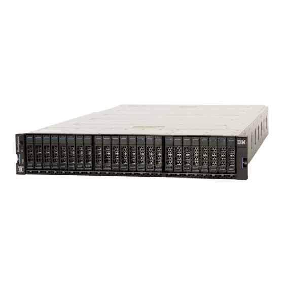
IBM FlashSystem 7200 Control
Enclosure Getting Started Guide
Getting started
This document describes the installation procedures for your IBM
system configuration. This document is intended to be used by persons who are experienced with installing these systems.
System
IBM FlashSystem
7200 control enclosure
®
Before you use this information and the product it supports, read the following topics:
•
Installation worksheets
•
Safety and environmental notices
•
Notices
on page 15
•
IBM Environmental Notices and User Guide and IBM Safety Notices (provided on a DVD with your product order)
IBM Knowledge Center (https://ibm.biz/BdqxdY) contains more information about preparing the physical environment before the
installation; it also provides information about configuring, managing, and servicing the system after installation. The IBM Knowledge
Center is updated between product releases to provide the most current documentation.
Unpacking and verifying the contents
Before you start the installation process, ensure that the following items are available.
•
Philips screw driver
•
Box knife
•
Flat-blade screw driver (optional)
•
Three Ethernet cables
The control enclosure and the following related parts are included in one box. The enclosed inventory sheet lists the part numbers of the
items that were ordered. Items, such as drives and networking adapters, are preinstalled inside each node canister.
•
Control enclosure with the following components preinstalled:
– Two node canisters with optional networking adapters, SFPs, and memory
Each node canister contains three networking adapter slots. The same number and type of adapters must be installed in each node
canister. The control enclosure can contain 0, 2, 4, or 6 networking adapters.
– Two power supply units (PSUs)
– A combination of 24 drives and drive blanks
The number of drives and drive blanks varies, according to the number of drives that were specified in the product order. For
example, if 12 drives were ordered, the drives and 12 drive blanks are preinstalled in the control enclosure.
•
Rail kit, which includes the left and right rails, and 8 securing M5 screws and locating pins.
•
Cables, if they were ordered, for the type and number of networking adapters that are installed in each node canister.
•
Two power cables.
on page 10
on page 14
control enclosure. It also contains information to help you plan the
®
MTMs
2076-824 and 2076-U7C
IBM
Advertisement
Table of Contents

Related Manuals for IBM 2076-824


Summary of Contents for IBM 2076-824
- Page 1 15 • IBM Environmental Notices and User Guide and IBM Safety Notices (provided on a DVD with your product order) IBM Knowledge Center (https://ibm.biz/BdqxdY) contains more information about preparing the physical environment before the installation; it also provides information about configuring, managing, and servicing the system after installation. The IBM Knowledge Center is updated between product releases to provide the most current documentation.
- Page 2 Unpack the control enclosure CAUTION: The weight of this part or unit is between 32 and 55 kg (70.5 and 121.2 lb). It takes three persons to safely lift this part or unit. (C010) To unpack the control enclosure, complete the following steps. If three persons or a lift are not available, more steps are required to remove some parts before the control enclosure can be installed.
- Page 3 Installing the support rails and enclosure into the rack Before you can install the control enclosure into the rack, you must first install the side support rails. 1. At each end of the side rail, grasp the tab and pull firmly to open the hinge bracket. 2.
-
Page 4: Removing And Replacing Parts
10.Reinstall the left and right end caps to the front of the enclosure. Removing and replacing parts If three persons or a lift are not available to install the control enclosure, the weight of the control enclosure must be reduced before it can be safely lifted. - Page 5 Removing and replacing a node canister in the control enclosure During installation, you might need to remove and replace the node canisters from the control enclosure. About this task • No tools are required to complete this task. Do not remove or loosen any screws. •...
-
Page 6: Removing And Replacing A Drive
Removing and replacing a drive Use the following procedures to remove and replace a drive or an IBM FlashCore Module (FCM) from a node canister. About this task • You must follow the recommended procedures for handling electrostatic discharge (ESD)-sensitive devices. -
Page 7: Connecting Sas Cables
Connect SAS port 3 of the bottom node canister in the control enclosure to SAS port 1 of the right expansion canister in the second expansion enclosure. For more information about 2U and 5U expansion enclosures, see IBM Knowledge Center (https://ibm.biz/BdqxdY). Connect networking cables To provide connectivity for the system, you must connect cables to the appropriate ports on the control enclosure. - Page 8 Connecting Ethernet cables 1. Connect Ethernet port 1 of each node canister to the IP network that will provide connection to the system management interfaces. Use the information that you provided in the Network cable worksheet on page 11. Ethernet port 1 can also be used for iSCSI connectivity to the system by hosts on the network. If the system contains more than one control enclosure, ensure port 1 of every node canister is connected to the same network to provide access if the configuration node fails.
-
Page 9: Powering On The System
Powering on the system After you install all hardware components, you must power on the system and check its status. Each control enclosure has two power supply units (PSUs). To provide redundancy in a power failure, connect the power cords to separate power circuits. Attention: Do not power on the system with any open bays or drive slots. -
Page 10: Installation Worksheets
5. Use the initialization GUI to enter the requested information, such as the management IP address and service IP addresses. (You need to set the IP address, subnet mask, and DNS server only when you do not want to use DHCP.) For more information, see Management and service address worksheet on page 11. -
Page 11: Supported Drives
Supported drives The following table lists the supported drives for the system. For more information about replaceable units, see IBM Knowledge Center. Table 2: Control enclosure drives FRU Part Number Description 01YM585 800 GB 2.5" NVMe Flash drive 01YM586 1.92 TB 2.5" NVMe Flash drive 01YM587 3.84 TB 2.5"... - Page 12 Table 4: Ethernet cable standards(continued) Ethernet port type Cable type Minimum standard Connector 10 Gbps onboard Ethernet ports Cat 6 (up to 55 m), Cat 6a or Cat 7 (up to RJ45 100 m) at 10 Gbps, or Cat 5e at 1 Gbps 25 Gbps Ethernet host interface adapter (must be ordered) Optical OM3 (up to 70 m) OM4 (up to 100 m)
- Page 13 Table 6: Ethernet adapter port connection worksheet Control Enclosure S/N: Ethernet Adapter Slot 3 Ethernet Adapter Slot 2 Ethernet Adapter Slot 1 Node canister 1 Port 10 Port 9 Port 8 Port 7 Port 6 Port 5 Switch Port Speed: 25 or 10 Gbps Cable type Node IP Subnet mask...
-
Page 14: Safety And Environmental Notices
2. Locate the IBM Systems Safety Notices with the user publications that were provided with your system hardware. 3. Find the matching identification number in the IBM Systems Safety Notices. Then, review the topics about the safety notices to ensure that you are in compliance. -
Page 15: Compliance Standards
IBM may not offer the products, services, or features discussed in this document in other countries. Consult your local IBM representative for information on the products and services currently available in your area. Any reference to an IBM product, program, or service is not intended to state or imply that only that IBM product, program, or service may be used. - Page 16 Any references in this information to non-IBM websites are provided for convenience only and do not in any manner serve as an endorsement of those websites. The materials at those websites are not part of the materials for this IBM product and use of those websites is at your own risk.
-
Page 17: Homologation Statement
International Business Machines Corp., registered in ® many jurisdictions worldwide. Other product and service names might be trademarks of IBM or other companies. The current list of IBM trademarks is available on the web at Copyright and trademark information at www.ibm.com/legal/copytrade.html. - Page 18 Der verantwortliche Ansprechpartner des Herstellers in der EU ist: IBM Deutschland GmbH Technical Relations Europe, Abteilung M456 IBM-Allee 1, 71139 Ehningen, Germany Tel: +49 800 225 5426 e-mail: Halloibm@de.ibm.com Generelle Informationen: Das Gerät erfüllt die Schutzanforderungen nach EN 55024 und EN 55032 Klasse A.
-
Page 19: Taiwan Notice
Properly shielded and grounded cables and connectors must be used in order to meet FCC emission limits. IBM is not responsible for any radio or television interference caused by using other than recommended cables and connectors, or by unauthorized changes or modifications to this equipment. - Page 20 This edition applies to version 8, release 3, modification 1, and to all subsequent modifications until otherwise indicated in new editions. Copyright International Business Machines Corporation 2020. © US Government Users Restricted Rights – Use, duplication or disclosure restricted by GSA ADP Schedule Contract with IBM Corp. (1P) P/N: 03GH378...