Table of Contents
Advertisement
Quick Links
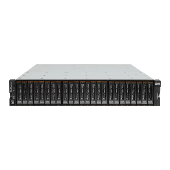
IBM FlashSystem 7200
IBM Storwize V7000 Gen3
NVMe Control Enclosure
Getting Started Guide
Overview
This document describes the installation procedures for the following IBM FlashSystem
information to help you plan the system configuration. This information applies to the following machine type and model (MTM) numbers.
System
IBM FlashSystem 7200 control enclosure
Storwize V7000 Gen3 NVMe control enclosure
Important: This document is intended to be used by persons who are experienced with installing these systems. Before you use this
information and the product it supports, read the following topics:
•
Installation worksheets
•
Safety and environmental notices
•
Notices
on page 13
•
IBM Systems Environmental Notices
IBM Knowledge Center (https://ibm.biz/BdqxdY) contains more information about preparing the physical environment before the
installation; it also provides information about configuring, managing, and servicing the system after installation. The IBM Knowledge
Center is updated between product releases to provide the most current documentation.
Unpacking and verifying the contents
Before you start the installation process, ensure that the following items are available.
•
Philips screw driver
•
Box knife
•
Flat-blade screw driver (optional)
•
Three Ethernet cables
The control enclosure and the following related parts are included in one box. The enclosed inventory sheet lists the part numbers of the
items that were ordered. Items, such as drives and networking adapters, are preinstalled inside each node canister.
•
Control enclosure with the following components preinstalled:
– Two node canisters with optional networking adapters, SFPs, and memory.
Each IBM FlashSystem 7200 node canister contains three networking adapter slots. The same number and type of adapters must be
installed in each node canister. The control enclosure can contain 0, 2, 4, or 6 networking adapters.
Each Storwize V7000 Gen3 node canister has three adapter slots. By default, slot 3 contains a 4-port 12 Gbps SAS networking
adapter. If ordered, the same number and type of networking adapters are installed in slots 1 and 2 of each node canister. The
control enclosure can contain 2, 4, or 6 networking adapters.
– Two power supply units (PSUs).
– A combination of 24 drives and drive blanks.
The number of drives and drive blanks varies, according to the number of drives that were specified in the product order. For
example, if 12 drives were ordered, the drives and 12 drive blanks are preinstalled in the control enclosure.
•
Rail kit, which includes the left and right rails, and 8 securing M5 screws and locating pins.
•
Cables, if they were ordered, for the type and number of networking adapters that are installed in each node canister.
•
Two power cables.
on page 8
on page 12
and
IBM Systems Safety Notices
and Storwize
®
MTMs
2076-824 and 2076-U7C
2076-724 and 2076-U7B
(provided on a DVD with your product order)
IBM
systems. It also contains
®
1
Advertisement
Table of Contents

Related Manuals for IBM FlashSystem 7200


Summary of Contents for IBM FlashSystem 7200
- Page 1 – Two node canisters with optional networking adapters, SFPs, and memory. Each IBM FlashSystem 7200 node canister contains three networking adapter slots. The same number and type of adapters must be installed in each node canister. The control enclosure can contain 0, 2, 4, or 6 networking adapters.
- Page 2 CAUTION: The weight of this part or unit is between 32 and 55 kg (70.5 and 121.2 lb). It takes three persons to safely lift this part or unit. (C010) Unpack the control enclosure To unpack the control enclosure, complete the following steps. If three persons or a lift are not available, more steps are required to remove some parts before the control enclosure can be installed.
-
Page 3: Removing And Replacing Parts
6. Secure the rear of the rail to the rear rack flange with two black M5 screws (5). 7. Repeat Step on page 2 through Step on page 3 to secure the opposite rail to the rack cabinet. 8. Remove each end cap from the front of the enclosure. Lift the bottom of each end cap 9. -
Page 4: Removing And Replacing A Drive
8. Press the release levers closed to fully engage the node canister into the enclosure. Press the latch ends to ensure that the latches are engaged with the control enclosure. Removing and replacing a drive Use the following procedures to remove and replace a drive or an IBM FlashCore Module (FCM) from a node canister. About this task •... -
Page 5: Connecting Sas Cables
5U expansion enclosures. The system supports an intermix of 2U and 5U expansion enclosures with a total chain weight of 10 in each of two SAS chains. For more information about expansion enclosures, see IBM Knowledge Center (https://ibm.biz/BdqxdY). 1. Using the supplied SAS cables, connect the control enclosure to the first expansion enclosure. -
Page 6: Powering On The System
Each control enclosure has PCIe slots that support optional networking adapters. However, the location requirements for the networking adapters differ between the FlashSystem 7200 and Storwize V7000 Gen3 control enclosures. Use the information that you entered in Network cable worksheets on page 9 to establish the proper connections. - Page 7 1. Ensure that the circuit breakers or switches of the power sources are turned on. 2. Ensure that each power cable is secured to each PSU on the back of the node. To do so, route each power cable through the retainer. The cable retainer has a curved opening that faces the rear of the PSU.
-
Page 8: Browser Considerations
Adding a control enclosure to an existing system If the system was already set up on another control enclosure, do not install it again on this control enclosure. Instead, use the management GUI to add the control enclosure to the system. 1. - Page 9 Use the following table to record the properties of the onboard Ethernet ports on each node canister of the control enclosure. The configuration of the onboard Ethernet ports for FlashSystem 7200 and Storwize V7000 Gen3 systems are the same. Control Enclosure S/N:...
- Page 10 Gateway VLAN ID FlashSystem 7200 Fibre Channel connections Each node canister supports 4-port 32 Gbps Fibre Channel (FC) adapters or 4-port 16 Gbps FC adapters. Install the FC networking adapters according to the following guidelines. Record the information about the FC port connections on each node canister in the following table.
- Page 11 Storwize V7000 Gen3 Ethernet networking adapters Each node canister also supports optional 2-port 25 Gbps internet Wide-area RDMA Protocol (iWARP) or RDMA over Converged Ethernet (RoCE) Ethernet networking adapters. Install the 25 Gbps Ethernet adapters according to the following guidelines. Record the port connections for the Ethernet adapters in the following table.
-
Page 12: Safety And Environmental Notices
2. Locate the IBM Systems Safety Notices document with the user publications that were provided with your system hardware. 3. Find the matching identification number in IBM Systems Safety Notices. Then, review the topics about the safety notices to ensure that you are in compliance. - Page 13 IBM may not offer the products, services, or features discussed in this document in other countries. Consult your local IBM representative for information on the products and services currently available in your area. Any reference to an IBM product, program, or service is not intended to state or imply that only that IBM product, program, or service may be used.
-
Page 14: Homologation Statement
Such information may be available, subject to appropriate terms and conditions, including in some cases, payment of a fee. The licensed program described in this document and all licensed material available for it are provided by IBM under terms of the IBM Customer Agreement, IBM International Program License Agreement or any equivalent agreement between us. - Page 15 This product is in conformity with the protection requirements of Directive 2014/30/EU of the European Parliament and of the Council on the harmonization of the laws of the Member States relating to electromagnetic compatibility. IBM cannot accept responsibility for any failure to satisfy the protection requirements resulting from a non-recommended modification of the product, including the fitting of non- IBM option cards.
- Page 16 This statement applies to products greater than 20 A per phase, three-phase. Japan Voluntary Control Council for Interference (VCCI) Notice Korea Notice People's Republic of China Notice Russia Notice Taiwan Notice...
- Page 17 Properly shielded and grounded cables and connectors must be used in order to meet FCC emission limits. IBM is not responsible for any radio or television interference caused by using other than recommended cables and connectors, or by unauthorized changes or modifications to this equipment.