
Related Manuals for Compaq StorageWorks SAN Switch Integrated/32


Summary of Contents for Compaq StorageWorks SAN Switch Integrated/32
- Page 1 StorageWorks by Compaq SAN Switch Integrated/32 and SAN Switch Integrated/64 Installation and Hardware Guide Third Edition January 2002 Part Number: AA-RPDFC-TE Compaq Computer Corporation...
- Page 2 Documentation, and Technical Data for Commercial Items are licensed to the U.S. Government under vendor's standard commercial license. Compaq shall not be liable for technical or editorial errors or omissions contained herein. The information is provided “as is” without warranty of any kind and is subject to change without notice. The warranties for Compaq products are set forth in the express limited warranty statements accompanying such products.
-
Page 3: Table Of Contents
Compaq Authorized Reseller ........ - Page 4 SAN Switch Integrated/32 and Integrated/64 Installation and Hardware Guide Chapter 2 Installing the SAN Integrated Switch Installation Considerations and Safety Guidelines ........2–1 Selecting an Operating Location .
- Page 5 Downloading Firmware from the Compaq Website ........5–1...
- Page 6 SAN Switch Integrated/32 and Integrated/64 Installation and Hardware Guide Taiwanese Notice ............A–6 Laser Devices .
- Page 7 Figures Figure 1–1: Front Panel Features of a IS/32 or IS/64-port SAN Integrated Switch ... . 1–3 Figure 1–2: Front panels of the IS/32 and IS/64 ........1–4 Figure 1–3: Logical view showing ISLs and user ports on the IS/32 and IS/64 .
- Page 9 Tables Table 3–1: Serial Port Pinouts ........... . 3–3 Table 3–2: Serial Port Settings.
-
Page 11: About This Guide
Integrated/32 and Integrated/64 by Compaq. In addition, this guide contains information regarding operation and troubleshooting. Naming Conventions Throughout this document, the StorageWorks SAN Switch Integrated/32 and SAN Switch Integrated/64, will be referred to as follows: Collectively, both models will be called the SAN Integrated Switch. -
Page 12: Related Documents
In addition to this guide, the following documentation provides useful information for installing, configuring, operating and upgrading your SAN Integrated Switch: Document: Part Number/Location: Compaq StorageWorks Fibre Channel SAN Switch AA-RNAPC-TE / Located on the StorageWorks 16-EL Installation and Hardware Guide SAN Switch Software CD... -
Page 13: Symbols In Text
About This Guide xiii Symbols in Text These symbols may be found in the text of this guide. They have the following meanings. WARNING: Text set off in this manner indicates that failure to follow directions in the warning could result in bodily harm or loss of life. CAUTION: Text set off in this manner indicates that failure to follow directions could result in damage to equipment or loss of information. -
Page 14: Rack Stability
SAN Switch Integrated/32 and Integrated/64 Installation and Hardware Guide Any surface or area of the equipment marked with these symbols indicates the presence of a hot surface or hot component. If this surface is contacted, the potential for injury exists. WARNING: To reduce the risk of injury from a hot component, allow the surface to cool before touching. -
Page 15: Getting Help
Compaq Technical Support In North America, call the Compaq technical support phone center at 1-800-652-6672 (1-800-OK-COMPAQ). This service is available 24 hours a day, 7 days a week. NOTE: For continuous quality improvement, calls may be recorded or monitored. Outside North America, call the nearest Compaq technical support phone center. -
Page 16: Compaq Website
SAN Switch Integrated/32 and Integrated/64 Installation and Hardware Guide Compaq Website The Compaq website has latest information on this product as well as the latest firmware. You can access the Compaq website by logging on to the Internet at http://www.compaq.com/storage. -
Page 17: Overview
Integrated Switch consists of a 14U (25-inch) high rack-mountable enclosure with six integrated switch elements that are preconfigured with all necessary interswitch cabling for quick installation. Each switch element is a Compaq StorageWorks Fibre Channel SAN Switch 16-EL. All ports for the SAN Integrated Switch are configured with removable short wave Gigabit Interface Converter (GBIC) modules. -
Page 18: Features Of The San Integrated Switch
SAN fabric. The SAN Integrated Switch supports F_port, FL_port, and E_port connections and Distributed Name Server (DNS). Fully compatible with the entire Compaq StorageWorks SAN Switch product family, the SAN Integrated Switch enables customers to deploy SANs in a modular manner and scale storage environments as needed, while optimizing existing investments in server and storage infrastructure. -
Page 19: Front Panel
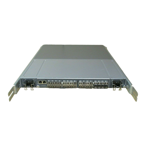
Overview 1–3 Front Panel The 32-port and 64-port models of the SAN Integrated Switch share the same basic features. They differ only in the wiring of ISL cables and the number of available user ports. Figure 1–1 shows the front panel of the SAN Integrated Switch, with all features common to both the IS/32 and IS/64. -
Page 20: Figure 1-2: Front Panels Of The Is/32 And Is/64
1–4 1–4 SAN Switch Integrated/32 and Integrated/64 Installation and Hardware Guide SAN Switch Integrated/32 and Integrated/64 Installation and Hardware Guide SHR-2195A Front panel of IS/32 Front panel of IS/64 Figure 1–2: Front panels of the IS/32 and IS/64 SHR-2196A indicates user port; interconnecting lines indicate ISLs ISL cable configuration on IS/32 ISL cable configuration on IS/64 Figure 1–3: Logical view showing ISLs and user ports on the IS/32 and IS/64... -
Page 21: Installing The San Integrated Switch
Chapter Installing the SAN Integrated Switch This chapter covers the following topics: Installation Considerations and Safety Guidelines, page 2-1 Unpacking the SAN Integrated Switch, page 2-5 Identifying the Crate Contents, page 2-7 Installing the SAN Integrated Switch, page 2-8 Installation Considerations and Safety Guidelines WARNING: The SAN Integrated Switch weighs approximately 200 pounds. -
Page 22: Selecting An Operating Location
2–2 2–2 SAN Switch Integrated/32 and Integrated/64 Installation and Hardware Guide SAN Switch Integrated/32 and Integrated/64 Installation and Hardware Guide Make sure the airflow to the SAN Integrated Switch is at least 300 cubic feet per minute (cfpm). Verify there is space in the rack. The SAN Integrated Switch is 14U (25 inches) high. Heaviest components should always be installed in the bottom of the rack. -
Page 23: Power Requirements
Installing the SAN Integrated Switch 2–3 CAUTION: The cooling air for all components in the rack must flow in the same direction to allow for proper temperature control. Do not block the front or rear air vents. The switch uses ambient air for cooling. Power Requirements The switch element is powered up as soon as the power cable is connected to the switch and to a power source. -
Page 24: Figure 2-1: Distributing Switch Elements Among Multiple Power Sources
2–4 2–4 SAN Switch Integrated/32 and Integrated/64 Installation and Hardware Guide SAN Switch Integrated/32 and Integrated/64 Installation and Hardware Guide SHR-2197A Figure 2–1: Distributing switch elements among multiple power sources Each of the two power sources is best protected by its own Uninterruptable Power Supply (UPS). -
Page 25: Items Required For Installation
Installing the SAN Integrated Switch 2–5 Items Required for Installation The following items are required to install the SAN Integrated Switch: Lift device (recommended) SAN Integrated Switch (IS/32 or IS/64) Mounting brackets and hardware Number 2 Phillips screwdriver Minimum 30-inch deep rack space, 14 rack units (RU) high and 19 inches wide Six power outlets, one for each switch element (preferably distributed across two power sources) Unpacking the SAN Integrated Switch... -
Page 26: Figure 2-2: San Integrated Switch On Pallet, With Crate Cover Removed
2–6 2–6 SAN Switch Integrated/32 and Integrated/64 Installation and Hardware Guide SAN Switch Integrated/32 and Integrated/64 Installation and Hardware Guide SHR-2198A Pallet Box containing mounting hardware SAN Integrated Switch Screws which attach SAN Integrated Switch to pallet brackets (two per bracket/four brackets) Box containing documentation kit and cables Figure 2–2: SAN Integrated Switch on pallet, with crate cover removed... -
Page 27: Identifying The Crate Contents
Installing the SAN Integrated Switch 2–7 Identifying the Crate Contents The following items are included in the SAN Integrated Switch crate (see Figure 2–3). SHR-2199A Figure 2–3: Package contents... -
Page 28: Installing The San Integrated Switch
2–8 2–8 SAN Switch Integrated/32 and Integrated/64 Installation and Hardware Guide SAN Switch Integrated/32 and Integrated/64 Installation and Hardware Guide Crate Contents Quantity Fully configured SAN Integrated Switch Fibre Channel SAN Switch 16-EL switch elements interconnected with ISLs Left and Right Front Rail Bracket 1 of each Documentation and software kit AC power cords with standard 3-prong connectors... -
Page 29: Figure 2-4: Installing The San Integrated Switch In The Rack
Installing the SAN Integrated Switch 2–9 SHR-2200A Air flow Left and Right Upper Rear Brackets (straight section) Rails in Rack Left and Right Upper Rear Brackets (L section) Left and Right Rack Mount Brackets Cage nuts Figure 2–4: Installing the SAN Integrated Switch in the rack NOTE: The rail is divided into units, each unit is marked with a small round hole and has three square openings for mounting equipment. - Page 30 2–10 2–10 SAN Switch Integrated/32 and Integrated/64 Installation and Hardware Guide SAN Switch Integrated/32 and Integrated/64 Installation and Hardware Guide 2. Attach the Rack Mount Brackets (item 3) to the rack rails (item 2) to create a shelf: a. Loosen the screws which connect the two parts of each Rack Mount Bracket. b.
-
Page 31: Figure 2-5: Align Holes In Upper Rear Bracket With The Four Screw Holes
Installing the SAN Integrated Switch 2–11 SHR-2201A Figure 2–5: Align holes in Upper Rear Bracket with the four screw holes on the SAN Integrated Switch d. Attach the straight section of the right bracket to the SAN Integrated Switch with four 8-32 X 5/16 inch Phillips countersunk screws. -
Page 32: Figure 2-6: Insert The Cage Nuts Into The Rail
2–12 2–12 SAN Switch Integrated/32 and Integrated/64 Installation and Hardware Guide SAN Switch Integrated/32 and Integrated/64 Installation and Hardware Guide SHR-2211A Cage nut Square opening Left front rail Upper screw of rack mount bracket Figure 2–6: Insert the cage nuts into the rail 5. - Page 33 Installing the SAN Integrated Switch 2–13 f. Slowly and carefully, maneuver the SAN Integrated Switch into the rack, until it is fully supported by the Rack Mount Brackets. g. Remove the lift. 6. Secure the SAN Integrated Switch in the rack: a.
-
Page 34: Figure 2-7: Front And Rear Views Of Power Cable Installation
2–14 2–14 SAN Switch Integrated/32 and Integrated/64 Installation and Hardware Guide SAN Switch Integrated/32 and Integrated/64 Installation and Hardware Guide 7. Install each of the six AC power cords (see Figure 2–7): a. Route each cord from the rear of the SAN Integrated Switch, through the power cable channel. -
Page 35: Configuring The San Integrated Switch
Chapter Configuring the SAN Integrated Switch This chapter covers the following topics: Items Required for Configuring the SAN Integrated Switch, page 3-2 Powering Up the Switch Elements, page 3-2 Connecting the Serial and Ethernet Cables, page 3-2 Modifying the Domain IDs, page 3-8 Specifying the Desired Status Policies, page 3-9 Checking the Fabric for Port or ISL Issues, page 3-9 Checking Each Switch Element for Port or ISL Issues, page 3-10... -
Page 36: Items Required For Configuring The San Integrated Switch
3–2 3–2 SAN Switch Integrated/32 and Integrated/64 Installation and Hardware Guide SAN Switch Integrated/32 and Integrated/64 Installation and Hardware Guide Items Required for Configuring the SAN Integrated Switch Prior to configuring the SAN Integrated Switch, make sure you have the following: Serial cable to connect the workstation to each of the switch elements Six unused IP addresses, one for each switch element Workstation that has a terminal emulator application (such as HyperTerminal). -
Page 37: Connecting The Serial Cable
NOTE: Do not use the serial port during normal operation or for regular maintenance. The serial cable is provided with the SAN Integrated Switch. To order a serial cable through your Compaq sales representative or authorized reseller, use part number 230436-B21. (This number replaces 188851-B21.) IMPORTANT: Keep the serial cable in a safe location. -
Page 38: Figure 3-1: Connecting The Serial Cable
3–4 3–4 SAN Switch Integrated/32 and Integrated/64 Installation and Hardware Guide SAN Switch Integrated/32 and Integrated/64 Installation and Hardware Guide SHR-2203A DB9 serial port Serial cable Workstation Figure 3–1: Connecting the serial cable... -
Page 39: Connecting Through A Workstation
Configuring the SAN Integrated Switch 3–5 Connecting Through a Workstation Use these steps to execute initial switch element operations through a workstation connected to the serial port on the SAN Integrated Switch. 1. Disable any serial communication programs running on the workstation, such as synchronization programs for PDA. - Page 40 3–6 3–6 SAN Switch Integrated/32 and Integrated/64 Installation and Hardware Guide SAN Switch Integrated/32 and Integrated/64 Installation and Hardware Guide Each switch element has a preset, default Ethernet IP address and a default Ethernet subnet mask. Replace the default IP address and Ethernet subnet mask for each of the six switch elements, with the address using the ipAddrSet Telnet command and the address information provided by your LAN administrator (see Step 3 below).
-
Page 41: Connecting The Ethernet Cables
2. Access each switch element through the network connection. You can manage the individual switch elements using Web Management Tools or Telnet commands. For detailed information on Telnet commands and managing your switch elements, refer to the Compaq StorageWorks Fibre Channel SAN Switch Management Guide. -
Page 42: Modifying The Domain Ids
3–8 3–8 SAN Switch Integrated/32 and Integrated/64 Installation and Hardware Guide SAN Switch Integrated/32 and Integrated/64 Installation and Hardware Guide Modifying the Domain IDs The default domain IDs on the six switch elements shipped with the SAN Integrated Switch are 231, 232, 233, 234, 235, and 236, respectively. If you are connecting a SAN Integrated Switch in an existing SAN, you may have to change the Domain ID of each switch element. -
Page 43: Specifying The Desired Status Policies
Configuring the SAN Integrated Switch 3–9 Specifying the Desired Status Policies Use these steps to specify the status policies. 1. Log on with administrative privileges to the first switch element, using a Telnet connection. login: admin password: password 2. At the prompt, enter the command. -
Page 44: Checking Each Switch Element For Port Or Isl Issues
6. Close the terminal emulation program, disconnect the serial cable from the workstation and the switch element, and cover the serial port. For more information on Telnet commands, refer to the Compaq StorageWorks Fibre Channel SAN Switch Management Guide, Part Number AA-RMMJB-TE. -
Page 45: Saving And Restoring The Switch Element Configuration Settings
Configuring the SAN Integrated Switch 3–11 Saving and Restoring the Switch Element Configuration Settings Save your switch element configuration settings using the configUpload Telnet command for a switch element failure emergency. In order to restore your saved configuration settings, use the configDownload Telnet command. When replacing an old switch element with a new one, a configUpload should be taken from the old switch element to retain the configuration and parameter settings. -
Page 46: Installing An Ftp Server
3–12 3–12 SAN Switch Integrated/32 and Integrated/64 Installation and Hardware Guide SAN Switch Integrated/32 and Integrated/64 Installation and Hardware Guide Installing an FTP Server Use these steps to install and configure a Windows NT or 2000 FTP server. 1. Create a folder to hold the switch element firmware and configuration files. 2. -
Page 47: Table 3-3: Syntax Of A Name: Value Pair
Configuring the SAN Integrated Switch 3–13 switch:admin>configUpload Server Name or IP Address [host]: IP Address for Server: User Name [user]: File Name [config.txt]: Protocol (RSHD or FTP) [rshd]: Figure 3–3: configUpload command example 1 An upload may fail for one of the following reasons: The switch element does not recognize the host name. -
Page 48: Configupload Parameters
3–14 3–14 SAN Switch Integrated/32 and Integrated/64 Installation and Hardware Guide SAN Switch Integrated/32 and Integrated/64 Installation and Hardware Guide The second section contains general switch element configuration variables, such as diagnostic settings, fabric configuration settings, and SNMP settings. This section corresponds to the output of the cfgShow command (after the first few lines), although there are more lines uploaded than shown by the command. -
Page 49: Downloading A Configuration
Configuring the SAN Integrated Switch 3–15 Downloading a Configuration Use these steps to download a configuration. 1. From the workstation, establish a Telnet connection to the switch element, and log on with administrative privileges. 2. Enter the switchDisable command to disable the switch element. 3. -
Page 50: Configdownload Parameters
3–16 3–16 SAN Switch Integrated/32 and Integrated/64 Installation and Hardware Guide SAN Switch Integrated/32 and Integrated/64 Installation and Hardware Guide NOTE: The switch element's identity cannot be changed by configDownload. Parameters, such as the switch element's name and IP address, are ignored. They are the lines in the configuration file, which begin with “boot”. -
Page 51: Status Indicators
Configuring the SAN Integrated Switch 3–17 Status Indicators Each port contains an indicator that shows the status for that port (see Table 3–4). Table 3–4: Port Status Indicators Indicators Description No light showing No light or signal carrier (no module, no cable) for media interface LEDs. -
Page 52: Connecting The Fibre Channel Cables
3–18 3–18 SAN Switch Integrated/32 and Integrated/64 Installation and Hardware Guide SAN Switch Integrated/32 and Integrated/64 Installation and Hardware Guide Connecting the Fibre Channel Cables All cables connect at the front of the SAN Integrated Switch. Recommended cabling supports a transfer rate of 1.0625 gigabytes per second (GB/s). The SAN Integrated Switch product includes fiber-optic cables for the ISL ports. -
Page 53: Table 3-7: Fibre Channel Cabling Specifications
125 µm cladding diameter fiber optic duplex cable Table 3–8 lists the Fibre Channel cable part numbers and length. Table 3–8: Fibre Channel Cabling Part Numbers Compaq Part Number Cable Type Cable Length 234457-B21 Multi-mode fiber 6.6 ft (2 m) -
Page 54: Connecting Fibre Channel Cables To The Gbics
3–20 3–20 SAN Switch Integrated/32 and Integrated/64 Installation and Hardware Guide SAN Switch Integrated/32 and Integrated/64 Installation and Hardware Guide Connecting Fibre Channel Cables to the GBICs Connect the Fibre Channel cables to the user GBICs as appropriate to the fabric topology. If you want to install single-mode fiber cables, you will need to replace the factory-installed short wave GBIC modules with long wave GBIC modules. -
Page 55: Repair And Replacement
Do not disassemble, crush, puncture, short external contacts, or dispose of in fire or water. NOTE: For information on diagnostics and error messages with regard to the switch element, refer to the appropriate chapters in the Compaq StorageWorks Fibre Channel SAN Switch 16-EL Installation and Hardware Guide. -
Page 56: Replacing A Gbic Module
Replacing a GBIC Module Replacement GBIC modules for the Fibre Channel SAN Switches must be ordered separately. The Compaq part number for the shortwave optical GBIC module for multi-mode cable is 380561-B21. Two longwave GBIC modules and a short single-mode test cable can be ordered in a kit (part number 340412-B21). -
Page 57: Installing A Gbic Module
Repair and Replacement 4–3 If you are using any other type of GBIC module, squeeze the side prongs and carefully pull out the GBIC module. Figure 4–2 shows a squeeze-prong GBIC module. Figure 4–2: Squeeze-prong GBIC module Installing a GBIC Module To install a GBIC module: 1. -
Page 58: Replacing The Switch Element
Battery Replacement Notice, page A-8 NOTE: Please review the You can access the Compaq website for the latest firmware by logging on to the Internet at http://www.compaq.com/storage. All switch elements in the SAN must be running the same firmware version. To check the version, log on with administrative privileges to the switch element, using a Telnet connection. -
Page 59: Removing The Switch Element
Repair and Replacement 4–5 Removing the Switch Element To remove the switch element from the SAN Integrated Switch fabric: 1. Label all cables on the switch element being replaced, prior to disconnecting them. 2. Identify the WWN and the Domain ID of the switch element being replaced. If this information is already recorded, continue with Step 3. - Page 60 4–6 4–6 SAN Switch Integrated/32 and Integrated/64 Installation and Hardware Guide SAN Switch Integrated/32 and Integrated/64 Installation and Hardware Guide 3. If the switch element being replaced is partly or fully operational, back up the current configuration. Refer to the section on Saving and Restoring the Switch Element Configuration Settings, page 3-11.
-
Page 61: Figure 4-3: Replacing The Switch Element From The San Integrated Switch
Repair and Replacement 4–7 5. Remove the faulty switch element from the SAN Integrated Switch (see Figure 4–3). SHR-2212A Self-retaining screws (2) Switch element Figure 4–3: Replacing the switch element from the SAN Integrated Switch a. Unscrew the two 1/4-20 self-retaining screws that fasten the switch element brackets to the SAN Integrated Switch (item 1). -
Page 62: Figure 4-4: The Switch Element With Slide Mounting Brackets
4–8 4–8 SAN Switch Integrated/32 and Integrated/64 Installation and Hardware Guide SAN Switch Integrated/32 and Integrated/64 Installation and Hardware Guide 6. Remove the two mounting brackets from the switch element by unscrewing the four 8/32 x .312 Phillips panhead screws in each bracket, setting the brackets and screws aside for the new switch element (see Figure 4–4). -
Page 63: Installing The Replacement Switch Element
Repair and Replacement 4–9 Installing the Replacement Switch Element To install the replacement switch element in the chassis: IMPORTANT: To perform step , follow the procedure and read the cautionary note in Installing a GBIC Module, page 4-3 1. Insert the GBICs into the new switch element, inserting each GBIC into the port until it is firmly seated and the latching mechanism locks. -
Page 64: Configuring The Replacement Switch Element
4–10 4–10 SAN Switch Integrated/32 and Integrated/64 Installation and Hardware Guide SAN Switch Integrated/32 and Integrated/64 Installation and Hardware Guide Configuring the Replacement Switch Element To configure the replacement switch element: 1. Log on with administrative privileges to the new switch element, using a Telnet connection. - Page 65 Repair and Replacement 4–11 5. Install firmware version 2.1.9g or later on the new switch element IMPORTANT: All switch elements in the SAN must be running at the same firmware version level, and all fabric parameters must be the same, except for the Fibre Channel IP Address and the Domain ID.
-
Page 66: Adding The New Switch Element To The Integrated Fabric
4–12 4–12 SAN Switch Integrated/32 and Integrated/64 Installation and Hardware Guide SAN Switch Integrated/32 and Integrated/64 Installation and Hardware Guide 7. Restore saved switch element configuration. If you saved the switch configuration information to a server, you must restore it. a. -
Page 67: Table 4-1: Group Information
Repair and Replacement 4–13 SAN Integrated Switch Model Matrix Diagram Table 4–2, Page 4-16 Figure 4–5, Page 4-18 IS/32 Table 4–3, Page 4-17 Figure 4–6, Page 4-18 IS/64 c. Line up the keyed (ridged) side of the cable-end with the notch in the GBIC. d. -
Page 68: Replacing Isl Cables
4–14 4–14 SAN Switch Integrated/32 and Integrated/64 Installation and Hardware Guide SAN Switch Integrated/32 and Integrated/64 Installation and Hardware Guide 6. Provide the WWN of the new switch element to each of the existing switch elements in the group. a. Log on to one of the other switch elements in the group with administrative privileges, using a Telnet connection. -
Page 69: Disconnecting The Faulty Fiber-Optic Cable
Repair and Replacement 4–15 Disconnecting the Faulty Fiber-Optic Cable NOTE: To replace the ISL cable, it is not necessary to power down the switch elements before disconnecting ISL cables. 1. Disconnect each end of the damaged ISL cable by firmly grasping the connector housing and pulling the cable from the GBIC. -
Page 70: Table 4-2: Cable Configuration For Is/32
4–16 4–16 SAN Switch Integrated/32 and Integrated/64 Installation and Hardware Guide SAN Switch Integrated/32 and Integrated/64 Installation and Hardware Guide The following tables show ISL port interconnectivity in a SAN Integrated Switch. Use the corresponding table for your model: IS/32 (Table 4–2) or IS/64 (Table 4–3). Table 4–2: Cable Configuration for IS/32 Cable Color Connect from... -
Page 71: Table 4-3: Cable Configuration For Is/64
Repair and Replacement 4–17 Table 4–3: Cable Configuration for IS/64 Cable Color Connect from Connect to Lavender SW 1 - PORT 8 SW 2 - PORT 12 SW 1 - PORT 9 SW 2 - PORT 13 Yellow SW 1 - PORT 10 SW 3 - PORT 12 SW 1 - PORT 11 SW 3 - PORT 13... -
Page 72: Figure 4-5: The Isl Cabling Diagram For An Is/32
4–18 4–18 SAN Switch Integrated/32 and Integrated/64 Installation and Hardware Guide SAN Switch Integrated/32 and Integrated/64 Installation and Hardware Guide Following are representations of the ISL cabling diagrams for the SAN Integrated Switch. See Figure 4–5 for the IS/32 and Figure 4–6 for the IS/64. Refer to the color-coded ISL cabling diagram on the front of your switch. -
Page 73: Upgrading Firmware
The version command in Telnet The Switch Management Application page in Web Management Tools Refer to the Compaq StorageWorks Fibre Channel SAN Switch Management Guide for more information on Telnet commands and Web Management Tools. Downloading Firmware from the Compaq... -
Page 74: Upgrading Firmware Using Web Management Tools
5–2 5–2 SAN Switch Integrated/32 and Integrated/64 Installation and Hardware Guide SAN Switch Integrated/32 and Integrated/64 Installation and Hardware Guide Upgrading Firmware Using Web Management Tools The SAN Integrated Switch should be running firmware Version 2.x.x. In the event a firmware upgrade is needed, use the following procedure. -
Page 75: Figure 5-1: Firmware Upgrade Page Example
Upgrading Firmware 5–3 Figure 5–1: Firmware upgrade page example 6. Enter the host name or host IP address in the Host Name or Host IP field. NOTE: For Windows 9x, Windows 2000, Windows NT only, enter the IP address. 7. Enter a user name in the Remote User Name field. NOTE: For Windows 9x, Windows 2000, and Windows NT only, enter the default name user. -
Page 76: Upgrading Firmware Using A Telnet Command
Windows NT Alpha, or Compaq Tru64 UNIX. Windows NT Intel Host To load the firmware from a Compaq PC running Windows NT Intel: 1. Copy the files RSHD.EXE and CAT.EXE to the root directory (for example, C) on the host system. These files are found in D:\DSGGB\FIRMWARE\NTINTEL\RSHD.EXE... -
Page 77: Windows Nt Alpha Host
Upgrading Firmware 5–5 7. At the prompt, type firmwareDownload "192.168.60.200", "administrator" , "V2.x.x" where “192.168.60.200” is the IP address of your host computer, “administrator” is the account you are using to run RSHD.EXE, and “V2.x.x” is the firmware image to be downloaded to the switch. -
Page 78: Compaq Tru64 Unix Host
8. Click the Telnet window and enter the reboot command. The switch restarts and copies the firmware into RAM. Compaq Tru64 UNIX Host To load the firmware from a host running Compaq Tru64 UNIX: 1. Mount the CD device by using the following command: mount –t cdfs –r /dev/rz5c /mnt where rz5c is the device name for the CD. - Page 79 Upgrading Firmware 5–7 4. Telnet to the switch by entering: telnet <switch_hostname> user: admin pswd: <password> NOTE: You can substitute the IP address of the switch for <switch_hostname>. 5. To download the firmware from the host system to the switch flash memory, enter the following command line at the <switch>:admin>...
-
Page 81: Regulatory Compliance Notices
Numbers For the purpose of regulatory compliance certifications and identification, your Compaq StorageWorks SAN Integrated Switch is assigned a Compaq series number. The Compaq series number for this product is Series NA2104. The SAN Integrated Switch series number can be found on the product label, along with the required approval markings and information. -
Page 82: Federal Communications Commission Notice
A–2 SAN Switch Integrated/32 and Integrated/64 Installation and Hardware Guide Federal Communications Commission Notice Part 15 of the Federal Communications Commission (FCC) Rules and Regulations has established Radio Frequency (RF) emission limits to provide an interference-free radio frequency spectrum. Many electronic devices, including computers, generate RF energy incidental to their intended function and are, therefore, covered by these rules. -
Page 83: Declaration Of Conformity For Products Marked With Fcc
For questions regarding your product, contact Compaq Computer Corporation P. O. Box 692000, Mail Stop 530113 Houston, Texas 77269-2000 or call 1-800-652-6672 (1-800-OK COMPAQ). NOTE: For continuous quality improvement, calls may be recorded or monitored. For questions regarding this FCC declaration, contact Compaq Computer Corporation P. -
Page 84: Modifications
Modifications The FCC requires the user to be notified that any changes or modifications made to this device that are not expressly approved by Compaq Computer Corporation may void the user’s authority to operate the equipment. Network and Serial Cables Connections to this device must be made with shielded cables with metallic RFI/EMI connector hoods in order to maintain compliance with FCC Rules and Regulations. -
Page 85: European Union Notice
Regulatory Compliance Notices A–5 European Union Notice Products with the CE Marking comply with both the EMC Directive (89/336/EEC) and the Low Voltage Directive (73/23/EEC) issued by the Commission of the European Community. Compliance with these directives implies conformity to the following European Norms (the equivalent international standards are in parenthesis): EN55022 1998 (CISPR 22)—Electromagnetic Interference EN55024 1998 (IEC61000-4-2, IEC61000-4-3, IEC61000-4-4, IEC61000-4-5,... -
Page 86: San Switch Integrated/32 And Integrated/64 Installation And Hardware Guide
SAN Switch Integrated/32 and Integrated/64 Installation and Hardware Guide Taiwanese Notice Laser Devices All Compaq systems equipped with a laser device comply with safety standards, including International Electrotechnical Commission (IEC) 825. With specific regard to the laser, the equipment complies with laser product performance standards set by government agencies as a Class 1 laser product. -
Page 87: Compliance With International Regulations
All Compaq systems equipped with laser devices comply with appropriate safety standards including IEC 825. Laser Product Label The following label or equivalent is located on the surface of the Compaq supplied laser device. This label indicates that the product is classified as a CLASS 1 LASER PRODUCT. This label appears on a laser device installed in your product. -
Page 88: Battery Replacement Notice
Replacement is to be done by a Compaq authorized service provider using the Compaq spare designated for this product. For more information about battery replacement or proper disposal, contact your Compaq authorized reseller or your authorized service provider. -
Page 89: Electrostatic Discharge
Appendix Electrostatic Discharge This appendix covers the following topics: Precautions Against Electrostatic Discharge, page B-1 Grounding Methods, page B-2 Precautions Against Electrostatic Discharge To prevent damaging the system, be aware of the precautions you need to follow when setting up the system or handling parts. A discharge of static electricity from a finger or other conductor may damage system boards or other static-sensitive devices. -
Page 90: Grounding Methods
Use a portable field service kit with a folding static-dissipating work mat. If you do not have any of the suggested equipment for proper grounding, have your Compaq authorized reseller install the part. NOTE: For more information on static electricity, or for assistance with product installation,... -
Page 91: Weight Specifications
Appendix Specifications This appendix covers the following topics: Weight Specifications, page C-1 Physical Dimensions, page C-2 Environmental Specifications, page C-2 GBICs, page C-3 Switch Element Specifications, page C-3 Factory Default Settings, page C-5 Weight Specifications Table C–1 describes the weight specifications of each aspect of the SAN Integrated Switch. -
Page 92: Physical Dimensions
C–2 SAN Switch Integrated/32 and Integrated/64 Installation and Hardware Guide Physical Dimensions The SAN Integrated Switch has a 14 Unit (25-inch) rack height, 19-inch rack width, and is 24 inches deep, fitting in a 30-inch deep rack. Table C–2: Dimensions for the SAN Integrated Switch Dimension Size Smallest Rack Space... -
Page 93: Gbics
Specifications C–3 GBICs The SAN Integrated Switch is compatible with the following types of GBICs: Shortwave Longwave Shortwave serial ID Longwave serial ID The SAN Integrated Switch product includes short wavelength GBICs for all ports, both ISL and user ports. Switch Element Specifications The specifications for the switch element (Fibre Channel SAN Switch 16-EL) are listed in Table C–4. -
Page 94: Switch Element Memory
C–4 SAN Switch Integrated/32 and Integrated/64 Installation and Hardware Guide Switch Element Memory The available memory for the switch element is as follows. Main Memory: 16 MB per switch Flash Memory: 4 MB per bank, with 2 banks, mirrored for redundancy Power Supply See Table C–5 for power supply requirements. -
Page 95: Table C-6: Factory Default Settings
Specifications C–5 Factory Default Settings The factory default settings for the switch are listed in Table C–6. Table C–6: Factory Default Settings Parameter Compaq Default Ethernet IP address Domain/Switch Name 10.77.77.77 231/ SW1 10.77.77.76 232 /SW2 10.77.77.75 233 /SW3 10.77.77.74 234 /SW4 10.77.77.73... - Page 96 C–6 SAN Switch Integrated/32 and Integrated/64 Installation and Hardware Guide Table C–6: Factory Default Settings (Continued) Parameter Compaq Default Firmware version v2.4.x or later Firmware date Flash date Boot prom date Licenses Web Tools, Fabric Zoning diag.postDisable fabric.ops.mode.fcpProbeDisable fabric.ops.mode.isolate fabric.ops.mode.unicastOnly fabric.ops.mode.SeqSwitching...
- Page 97 Text size 0000d990 Data off 0000d9b0 Data addr 1033d9c0 Data size 00001b48 Magic 2112 OemLogoSet Fakemodel Software readable serial number Compaq switch serial number Supress F class SYNC IO mode Disable RLS probe Open send CLS rpc.rapid Translative mode Disable...
-
Page 99: Index
3–11 4–10 password 3–6 cfgShow 3–13 3–14 user ID 3–6 COM port 3–3 3–4 determining firmware revision 5–6 Compaq series number A–1 Distributed Name Server 1–2 configDefault 3–10 documents configDownload 3–11 3–14 3–15 3–16 related xii failure reasons 3–15... - Page 100 3–17 firmware flickering green 3–17 determining current version 5–1 interleaving green and yellow 3–17 downloading from the Compaq website 5–1 no light showing 3–17 upgrading using a Telnet command 5–4 port 3–17 upgrading using Web Management Tools slow green 3–17 5–2...
- Page 101 Index–3 Tru64 UNIX 5–6 serial port 1–3 Windows NT Alpha 5–5 connecting 3–3 Windows NT Intel 5–4 pinouts 3–3 locking bar Gigabit Interface Converter 4–2 series number A–1 slow green indicator 3–17 slow yellow indicator 3–17 modifications specifications FCC compliance statement A–4 dimensions C–4 switch C–3 squeeze-prong Gigabit Interface Converter 4–3...