Avidyne IFD550 Pilot's Manual
Hide thumbs
Also See for IFD550:
- Quick reference (10 pages) ,
- Quick reference (10 pages) ,
- Quick reference (30 pages)
Table of Contents
Advertisement
Quick Links
Advertisement
Table of Contents

Related Manuals for Avidyne IFD550


Summary of Contents for Avidyne IFD550
- Page 2 Revision History Revision Date of Release Reason for Release April 2015 Initial Release of document that coincided with Software Release 10.1.0.0 July 2015 Optimizations for black and white printing November 2015 Corrected several errors and added some additional descriptions December 2016 Update to accompany Software Release 10.2.0.0 March 2017...
-
Page 3: Table Of Contents
Line Select Keys ............1-10 Right Knob Labeling ............1-11 Color Philosophy ............1-11 GENERAL IFD OPERATIONS .......... 1-13 IFD540 & IFD550 Bezel Layout ........1-13 IFD510 & IFD545 Bezel Layout ........1-13 Power Control ..............1-16 Brightness Controls ............1-17 Start-Up Sequence ............ - Page 4 IFD500 Series Pilot Guide FMS Subsystem ..............3-1 FPL (FLIGHT PLAN) TAB ............ 3-2 FMS Basic Concepts ............3-2 Creating a New Flight Plan ..........3-9 Previewing Flight Plans ..........3-10 Selecting a Departure ............ 3-11 Inserting A Waypoint ............3-15 Inserting an Airway ............
- Page 5 IFD500 Series Pilot Guide Map Subsystem ..............4-1 MAP TAB ................4-2 Map Controls ..............4-2 Other Map Features ............4-6 Fuel Range Rings ............4-10 Decluttering The Map ............. 4-12 Map Panning ..............4-13 Graphical Flight Planning (“Rubber Banding”) ....4-14 Altitude Constraints On Map ..........
- Page 6 IFD500 Series Pilot Guide Updating Charts ............. 4-72 RADAR TAB ..............4-73 VIDEO TAB ................ 4-80 Aux Subsystem ..............5-1 AUDIO TAB ................5-2 Volume Control ..............5-2 Satellite Radio Tuning ............5-4 Com Presets † ..............5-6 UTIL (UTILITIES) TAB ............5-8 Timers ................
- Page 7 IFD500 Series Pilot Guide AUTO VLOC TUNING † ............ 6-19 TRANSITION ALTITUDES/LEVELS ........6-20 NAVIGATION MODE/CDI SCALE CHANGING ....6-22 APPROACH PROCEDURES ..........6-23 Automatic mode switching † .......... 6-24 Precision Approaches ............ 6-25 Non-Precision Approaches ..........6-26 Back Course Approaches † ........... 6-26 SBAS Approaches ............
- Page 8 IFD500 Series Pilot Guide CHARGING FROM THE USB ........... 7-44 INTEGRATION WITH THE IFD100 MOBILE APP .... 7-45 DEMO MODE ..............7-46 DATA TRANSFER TO/FROM EXTERNAL DEVICES ..7-49 REGULATORY COMPLIANCE STATEMENTS ....7-53 Radio Regulatory Compliance Statements† ....7-53 Déclaration(s) de conformité...
-
Page 9: System Overview
1 System Overview All images contained in this manual are for reference use only, and are subject to change. Avidyne strongly recommends that pilots use the IFD system only under VFR conditions until completely familiar with its operation and use. -
Page 10: Intended Function
IFD500 Series Pilot Guide INTENDED FUNCTION This manual describes the operation of the Avidyne IFD5xx series of equipment. Not all capabilities described herein are applicable to every model in the series. The IFD540 is the basis for capabilities described in the manual. Differences from the IFD540 are specifically identified throughout the manual. -
Page 11: Ifd510
TAWS (or HTAWS). IFD510 The Avidyne IFD510 differs from the IFD540 in that there is no internal VHF transceiver. Its primary function is to conduct GPS navigation, provided it is connected to an external navigation source selection annunciator and CDI/HSI indicator that are installed in the required field of view. -
Page 12: Ifd550
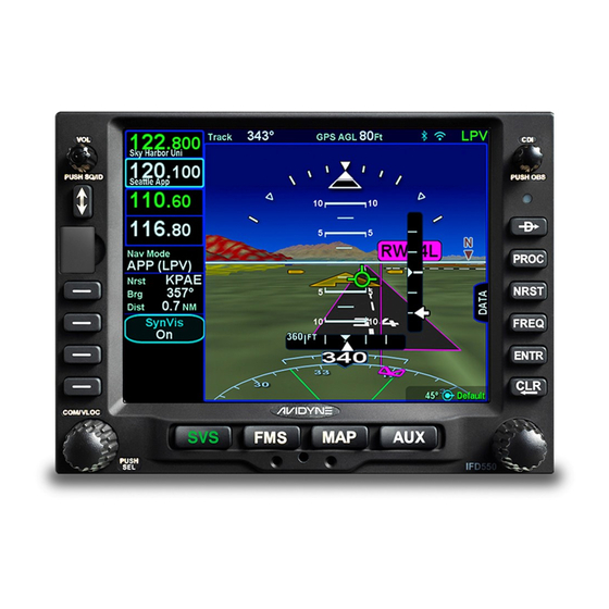
IFD500 Series Pilot Guide IFD550 The Avidyne IFD550 is a GPS, VHF Communication, and VHF Navigation transceiver whose primary function is to conduct VHF communication and navigation, and to serve as the primary navigation system for VFR and IFR VHF and GPS navigation and... -
Page 13: Ifd545
IFD545 The Avidyne IFD545 differs from the IFD550 in that there is no internal VHF transceiver. Its primary function is to conduct GPS navigation, provided it is connected to an external navigation source selection annunciator and a CDI/HSI indicator that is installed in the required field of view. - Page 14 IFD500 Series Pilot Guide and the volume knob is replaced by a single-function on/off button. IFD545 Integrated Flight Display The IFD545 also provides a synthetic terrain image to enhance the pilot’s awareness of their spatial position relative to the terrain, obstacles and known traffic. Pitch, roll, and skid/slip indicators also aid in attitude awareness.
- Page 15 IFD500 Series Pilot Guide DOCUMENTATION CONVENTION Throughout this document, capabilities that are not applicable to the IFD545 are identified using a † symbol. Also, capabilities that are applicable only to the IFD550 or IFD545 are identified using a ‡ symbol. System Overview...
-
Page 16: Functional Overview
IFD500 Series Pilot Guide FUNCTIONAL OVERVIEW The Avidyne Integrated Flight Display (IFD) system supports the following functions: Flight Management System (FMS) SBAS and non-SBAS GPS Navigation VHF Communication and Navigation (16W and 10W variants) † Synthetic Vision (SVS) ‡... - Page 17 IFD500 Series Pilot Guide Most functions revolve around the page keys that appear across the bottom edge of the bezel. Each of the pages has associated tabs, which contain related data, often in different views. These functions and tabs are covered in detail throughout this reference manual.
-
Page 18: Basic Concepts
Page Keys (IFD540 and IFD510) Page Keys (IFD550 and IFD545) LINE SELECT KEYS Line Select Keys (LSK), are the buttons found along the left side of the bezel. -
Page 19: Right Knob Labeling
IFD500 Series Pilot Guide the state shows the current state of that setting. Pressing the LSK or touching the label will change to the next state. An Action LSK is identified by a phrase shown in blue-green. The phrase is usually in verb-subject form, but there are exceptions when the verb is omitted (e.g. - Page 20 IFD500 Series Pilot Guide IFD Feature/Function Color Page keys Green - Active White - Available but not currently active Note: AUX can also be Red, Yellow, or Cyan if there is an active alert as described later in this manual FMS “Fly To”...
-
Page 21: General Ifd Operations
GENERAL IFD OPERATIONS IFD540 & IFD550 BEZEL LAYOUT The IFD540 and IFD550 have the same bezel layout except that the IFD550 has one extra page key labeled "SVS" to the left of the FMS key. Volume / Power / Squelch Knob... - Page 22 IFD500 Series Pilot Guide Power Dedicated Ambient Light GPS/OBS USB Port Button Function Keys Sensor Button Line Select Page Function Context Cam Latch Keys Keys Sensitive Knob Starting in the top left corner and working counter-clockwise around the bezel, the IFD has: ...
- Page 23 IFD500 Series Pilot Guide Six (6) Dedicated Function Keys consisting of: Direct-To (“─D─>”) Procedure (“PROC”) Nearest (“NRST”) Frequency List (“FREQ) Enter (“ENTR”) Clear (“CLR”) Ambient Light Sensor CDI Navigation Source knob † or GPS/OBS Button * * Applicable only to the IFD510 and IFD545 System Overview 1-15...
-
Page 24: Power Control
IFD500 Series Pilot Guide POWER CONTROL The IFD is typically powered by two circuit breakers; one for the VHF transceiver, and one for the remainder of the unit. The IFD will automatically start when the aircraft bus power is applied. It will take several seconds for the IFD to complete the power-up process. -
Page 25: Brightness Controls
IFD500 Series Pilot Guide BRIGHTNESS CONTROLS Each IFD has brightness controls to control both the bezel and the display brightness. Using the controls on the Setup Page, the user can specify whether brightness is controlled manually, using cockpit dimming controls, or using ambient light sensor (photocell) that is embedded in the bezel. -
Page 26: Start-Up Sequence
START-UP SEQUENCE The startup sequence of the IFD is as follows: An Avidyne logo will be displayed during system initialization and will be automatically removed when the IFD is initialized. The bezel keys will not be illuminated while the splash screen is present. - Page 27 FMS tabs for 10-30 seconds. Additionally, if an IFD550 or IFD545 unit has been exposed to extreme cold prior to start, it may take a warm up period to achieve standard performance.
- Page 28 IFD500 Series Pilot Guide TIPS AND TECHNIQUES Bluetooth/Networking Initialization Period The networking interfaces may experience a delay during post-start initialization before becoming functional. The icons in the upper right corner of the display will turn green when the interfaces are ready for use.
-
Page 29: Database Currency States
IFD500 Series Pilot Guide DATABASE CURRENCY STATES The following table describes the various database currency states that may be observed at startup: Database Status Message Color In Effect Valid Thru Light Green <Month, Day, Year> Has Expired Expired Yellow <Month, Day, Year> Not Yet Effective Effective Yellow... - Page 30 IFD500 Series Pilot Guide TIPS AND TECHNIQUES Manual Check of Database Dates Even if the databases are all current, you can still view the date/status of each database from the AUX page, Database Status display as described in Section 5 (page 5-90). 1-22 System Overview...
-
Page 31: Page Layout And Formats
The IFD540 and IFD550 will also show radio frequencies in the upper left corner. The frequencies to be shown are configurable. For the IFD510 and IFD545, that area can be configured to show other datablocks just like those on the right side of the page. - Page 32 IFD500 Series Pilot Guide desired tab. The last tab selected on any given page is retained and will be displayed when you return to that page. Split Page Layout Some pages can display datablocks along the right edge of the display.
-
Page 33: Com-Nav
IFD500 Series Pilot Guide COM-NAV † The VHF system consists of a communications transceiver that covers the frequency band from 118.0 MHz to 136.990 MHz and a navigation receiver that covers the frequency band from 108.0 MHz to 117.95 MHz. Both 25 kHz and 8.33 kHz spacing are supported. - Page 34 IFD500 Series Pilot Guide COOL FEATURE Multiple Standby Frequencies The com (or nav) frequencies can be formatted to act as a type of quick directory when set up ahead of time. This can be handy in local area operations when just a few standard frequencies are expected to be used for a flight –...
- Page 35 IFD500 Series Pilot Guide COOL FEATURE Decoded Facility Identifier The facility (e.g. Ground, Tower, Approach) for the Active and each displayed Standby com frequency are displayed in each com frequency slot. This is a handy reminder of the facility that is tuned in each slot.
- Page 36 (e.g. ATIS) while still connected to the active communications channel. Not all audio panels can support this capability. However, the Avidyne AMX240 and several other third party panels do offer this feature. Switching Tuning Controls The lower left knob is used to switch between display and control of communications radios, navigation radios, and a remote transponder (if equipped).
- Page 37 IFD500 Series Pilot Guide right of the decimal point. The slot being tuned is highlighted in reverse video as shown below. Manual Com/Nav Tuning Reverse Video The Standby frequency can also be tuned by touching the block on the display. When using this method, a virtual keyboard is displayed.
- Page 38 IFD500 Series Pilot Guide A more automated way to tune the communications radio is to use the frequency list, which is presented when the FREQ key is pressed. See the section on page 1-34 regarding operation of the frequency list. The Standby can also be tuned from other pages on the IFD such as the INFO or NRST Tab on the FMS page.
- Page 39 IFD500 Series Pilot Guide COOL FEATURE Shortcuts to Com Tuning Shortcuts are provided to aid speed and ease of manually entering a com frequency in the IFD. For example, there is no need to type the leading “1” for frequencies, the decimal point, trailing zeros or the thousandth digit.
- Page 40 IFD500 Series Pilot Guide into the standby slot and a small dialog box will be presented indicating the number of the preset list item that is now showing. Standby tuned from Com Preset List The swap frequency button performs the same action as pressing the Frequency Swap button on the bezel, including holding it down to tune the emergency frequency.
- Page 41 IFD500 Series Pilot Guide Third Party Radio Control Display Units Other remote tuning and frequency swapping capability is present when dedicated third-party radio control display units are wired into the aircraft. Usually in these cases, when the radio control display unit is active, the Active and Standby frequencies are only displayed on that external control display unit and not on the IFD, even though the actual radio is still housed inside the IFD.
-
Page 42: Frequency List
IFD500 Series Pilot Guide FREQUENCY LIST † The frequency list is displayed by pressing the “FREQ” key along the right edge of the bezel. It has three tabs along the top edge of the page: Airport – the most logical com frequencies (e.g. ATIS, ASOS, AWOS, CTAF, Tower, Ground, Clearance Delivery) associated with either the origin airport or destination airport (when airborne and more than 5nm... - Page 43 IFD500 Series Pilot Guide The list under each tab can be scrolled by swiping up or down on the touchscreen or by rotating the right inner knob. To move the cursor to the desired frequency, turn the right inner knob or touch the frequency.
-
Page 44: Transponder Control And Display
IFD500 Series Pilot Guide TRANSPONDER CONTROL AND DISPLAY If the IFD has been configured to communicate with a remote transponder, then the IFD will provide display and control of both transponder mode and code. Transponder Display The transponder mode and code is displayed in a datablock that can be configured to be displayed along the right and top sides of the display. - Page 45 IFD500 Series Pilot Guide Transponder Keyboard Transponder Code Entry To enter a transponder code using a keyboard, touch a transponder mode/code datablocks to display a transponder keyboard, and then enter the code. The new code is set after the fourth digit is entered. If an incorrect digit is entered, press the CLR button as required to backspace through the code.
- Page 46 IFD500 Series Pilot Guide GND - The transponder will respond to Mode S ground interrogations from surface movement radar. This mode is only available in installations that send a ground/air discrete signal to transponder SBY - The transponder is on, but will not reply to any interrogations Some aircraft installations include a ground/air state input, such as a gear squat switch or discrete input from an IFD.
-
Page 47: Direct-To Operations
IFD500 Series Pilot Guide DIRECT-TO OPERATIONS A dedicated Direct-To key is located along the right edge of the IFD bezel. Pressing that button from any page will display a green Direct-To dialog box that will be pre-populated with a logical waypoint. Direct-To Dialog and Confirmation Dialog Boxes If that pre-populated waypoint is the desired waypoint, press the “ENTR”... - Page 48 IFD500 Series Pilot Guide When the desired waypoint is displayed, press the knob button or ENTR key to accept Touch the waypoint field in the dialog box to generate a virtual keyboard and then use the keyboard to enter the desired waypoint identifier.
-
Page 49: Function Keys
IFD500 Series Pilot Guide FUNCTION KEYS In addition to the Direct-To and Frequency List keys that have already been described, the IFD has Nearest (“NRST”), Enter (“ENTR”), and Clear (“CLR”) keys that perform the following functions: NRST – Simultaneously jumps to a Nearest page (if not already there) and presents a list of the nearest airports to your present position. - Page 50 IFD500 Series Pilot Guide Pressing it a second time will step the reverse video over the Arrival field and present a drop down box of available published arrivals. Each subsequent press of the “PROC” key will step through all following destination airfield approaches and arrivals in the flight plan and wrap back around to the top of the flight plan.
-
Page 51: Touch Screen
IFD500 Series Pilot Guide TOUCH SCREEN The IFD uses a capacitive touch screen technology that allows multi-touch operation (e.g. two-fingered pinch zoom). Many types of gloves can be used during touch screen operations. The IFD employs a “hybrid touch” design in that virtually every interaction can be accomplished either through bezel controls or touch. - Page 52 IFD500 Series Pilot Guide Bezel-only Control Input Touch screen-only Control Functions Input Functions Selecting page keys (e.g. Map panning changing the “major” pages of FMS, MAP, AUX) Power on/off Graphical Flight Planning (“Rubber banding”) Changing the Primary Calling up a map page info box Navigation Source Starting the Frequency List Selecting a #2 or #3 standby...
- Page 53 IFD500 Series Pilot Guide Virtual Alpha Keyboard Virtual Numeric Keyboard Each keyboard has a scratchpad in the lower right corner. The scratchpad is a free text field for data entry with some data entry validity logic applied to the data that is trying to be entered. For example, when trying to enter an invalid frequency, the IFD will System Overview 1-45...
- Page 54 IFD500 Series Pilot Guide immediately sense that entry to be invalid and present an alert box stating the entry is invalid.† Validity logic is not applied on cross-side keyboards in dual IFD installations. Invalid Keyboard Entry Alert TIPS AND TECHNIQUES Optimal Touch Performance The touchscreen works best when the area being touched is maximized.
-
Page 55: Operations With Wireless Devices
IFD500 Series Pilot Guide OPERATIONS WITH WIRELESS DEVICES The IFD is capable of connecting to external devices over both Bluetooth and WiFi networks. Startup behavior When the IFD powers up, the IFD will attempt to configure the WiFi and Bluetooth interfaces just as they were when the IFD was last powered down. - Page 56 All labeled keys are fully functional. The light bulb key turns on backlighting for the keyboard. The vertical two-headed arrow key is primary/standby swap †. The Avidyne logo key is a space bar. The up/down arrow keys can be used for page navigation in the same way the bottom right inner and outer knobs on the IFD can navigate through page fields.
- Page 57 IFD500 Series Pilot Guide Avidyne Bluetooth Keyboard WiFi Connection The IFD is capable of supporting WiFi operations. Current supported functionality includes connectivity with third party applications running on WiFi capable devices including: Flight plan data streaming from the IFD to a third party application ...
- Page 58 IFD will select the LAN (hotspot). TIPS AND TECHNIEQUES Dual IFD Installations Should Only Use One WiFi For reliable WiFi operations, Avidyne recommends turning off WiFi on one of the IFDs (see the Setup Page). Bluetooth / WiFi Status Indications...
- Page 59 IFD500 Series Pilot Guide WiFi and Bluetooth Connected Icons If the user has disconnected WiFi / Bluetooth, the gray logos above are depicted with a slash through them indicating they are not connected due to being actively disabled by the user. System Overview 1-51...
-
Page 60: Dual Ifd Operations
IFD500 Series Pilot Guide DUAL IFD OPERATIONS Some installations may involve two IFDs that can work in a more integrated fashion. Method of Data Share (Dual IFD Operations) In a dual IFD installation, the IFDs can share information over the Byteflight digital data bus using RS232 Channel 3. - Page 61 IFD500 Series Pilot Guide Enables user waypoints to be synchronized across both IFDs Enables sensor settings and data (traffic, datalink, lightning, air data, etc) to be shared across both IFDs. NOTE Full Data Sharing Requires Consistent SBAS For complete data sharing between dual IFDs, both units will need to have the same SBAS antenna configuration –...
- Page 62 IFD500 Series Pilot Guide NOTE Sensor and Control Data Sharing Requires Consistent Software Versions For complete data sharing between dual IFDs, both units will need to have the same main software version. If the IFDs have different software versions, then the sensor and control data (e.g. weather, traffic, fuel, volumes, keyboard convenience mode, etc.) will not be shared between the IFDs.
- Page 63 User Profiles NOTE Data Sharing Tolerates Inconsistent Databases While Avidyne strongly recommends the databases on each IFD be kept up-to-date and on the same cycle, data sharing between IFDs as defined above in “Data Sharing (Dual IFD Operations)” is not disabled when different data cycles are present on the two IFDs.
-
Page 64: Sbas Vs Non-Sbas Operations
IFD500 Series Pilot Guide SBAS VS NON-SBAS OPERATIONS The IFD supports both SBAS and non-SBAS operations. In each case, the IFD is still considered a “/G” system for flight plan filing purposes. When configured for and connected to an approved SBAS antenna at installation, the IFD serves as a fully-certified SBAS GPS navigator. -
Page 65: Interaction With External Devices
IFD500 Series Pilot Guide INTERACTION WITH EXTERNAL DEVICES Each IFD is capable of communicating with several hundred third- party devices. Reference the Installation Manual for a complete list of devices supported and any hardware/software baseline restrictions. As a condition for certification, the IFD is approved for integration with all equipment the GNS 530 is approved for, plus the IFD is approved for integration with additional equipment beyond those authorized for use with the GNS system. -
Page 66: Before Takeoff Techniques
Set up the flight plan per your plans or the assigned ATC IFR clearance. If multiple pilots share the airplane, be sure to check the Setup page for your personal preferences. Avidyne recommends creating and using the Checklist utility and including a Before Takeoff checklist that meets your personal needs. -
Page 67: Svs Subsystem
IFD500 Series Pilot Guide 2 SVS Subsystem ‡ The Synthetic Vision System (SVS or SynVis) subsystem consists of a single page to aid in the pilot’s awareness of their spatial position relative to the terrain. SVS uses a GPS-based MSL altitude and a 9 arc-sec terrain database to display a 3D scene representing an “egocentric”... -
Page 68: Synthetic Vision Page
IFD500 Series Pilot Guide SYNTHETIC VISION PAGE If the IFD is receiving valid heading data, the circular green Total Velocity Vector (TVV)/Flight Path Marker (FPM) will be present in the display. The TVV/FPM indicates where the aircraft is actually going as compared to the yellow triangular Aircraft Reference Symbol (ARS) which indicates where the aircraft is pointing. - Page 69 IFD500 Series Pilot Guide Placing the TVV/FPM above the terrain means that the airplane will clear the terrain and vice versa. The terrain data and 9 arc- second resolution used in creating the synthetic terrain depiction is the same data and resolution used in the FLTA and TAWS calculations for consistency.
- Page 70 IFD500 Series Pilot Guide view. As traffic draws nearer to your ownship position, it grows in size in the SynVis scene. Traffic outside of 10nm will not be shown. However, if the traffic is a "Proximate Alert" (PA) or "Traffic Alert" (TA), it will be shown. 3D Traffic Symbology in SynVis Scene The TVV will grow in size when it is behind the deviation indicators or heading digital readout bubbles in order to stay...
- Page 71 IFD500 Series Pilot Guide IFD receives a valid METAR, the airfield flag will be color coded to represent the ceiling and visibility, consistent with the map. Airport Flags Any runway that is part of the active flight plan will be further outlined in magenta.
-
Page 72: Synthetic Vision With Datablocks
IFD500 Series Pilot Guide Heading Horizon Marks The Setup Page also provides a means to control whether the Horizontal Deviation Indicator (HDI) is always visible or shown only for approaches. HDI while enroute (“Always On”) SYNTHETIC VISION WITH DATABLOCKS The default SynVis view shows radio controls, datablocks, and LSKs on the left and the entire right side of the display shows the SynVis scene. -
Page 73: Synthetic Vision Obstacles
IFD500 Series Pilot Guide datablocks in a narrow area on the right side of the display. When configured to show datablocks, the datablocks overlay the terrain and the SynVis view is re-centered in the available space. To show the datablocks, touch the "Data" tab on the right side of the display. - Page 74 IFD500 Series Pilot Guide Any obstacle in the database within a 5nm radius of the aircraft position and whose top is within 2000’ vertically (above or below) of the aircraft altitude will generate a cyan (blue) threat bubble over the obstacle on the SynVis scene. Blue Obstacle Threat Bubbles Obstacles inside a 3nm radius of the aircraft position and whose top is between 100’...
- Page 75 IFD500 Series Pilot Guide Yellow Obstacle Threat Bubble Red Obstacle Threat Bubble SVS Subsystem...
- Page 76 IFD500 Series Pilot Guide Yellow or red highlighted obstacles on the SynVis scene will also display the MSL altitude of the obstacle top. Depiction of non-threat obstacles in the SynVis scene is governed in part by the Setup Page selections for the map. If obstacle filtering is disabled on the Setup Page, then all obstacles within 12nm will be displayed in the SynVis scene.
-
Page 77: Synthetic Vision Terrain Awareness
IFD500 Series Pilot Guide SYNTHETIC VISION TERRAIN AWARENESS Any terrain that is within a 10nm radius of aircraft position and between 100’ below aircraft altitude and 1000’ below aircraft altitude will generate yellow hatched indications on the SynVis scene and the map pages. Any terrain that is within a 10nm radius of the aircraft position and is 100’... -
Page 78: Svs Forward Looking Terrain Avoidance (Flta)
IFD500 Series Pilot Guide SVS FORWARD LOOKING TERRAIN AVOIDANCE (FLTA) FLTA alerting is triggered by either a projected imminent impact with terrain or obstacle or reduced terrain and obstacle clearance. Projected imminent impact with terrain occurs when the TVV/FPM is projected to intersect with terrain up to 3.0nm (yellow caution) or up to 1.5nm (red warning) in front of the aircraft flight path. - Page 79 IFD500 Series Pilot Guide Either terrain or obstacles can trigger FLTA alerts and they are distinguished via the CAS messaging and aural alerting. The difference between FLTA warnings and cautions is exclusively based on distance-to-go to projected impact points or reduced clearance areas.
-
Page 80: Flying Approaches With Synthetic Vision
IFD500 Series Pilot Guide FLYING APPROACHES WITH SYNTHETIC VISION As noted above, if a flight plan is active in the FMS, it will be depicted in the SynVis scene, presuming it falls within the current SynVis field of view. The lateral deviation Horizontal Deviation Indicator (HDI) and vertical deviation Vertical Deviation Indicator (VDI) will be automatically displayed and the arrowhead pointers indicate the direction and distance from desired glide path and glide slope. - Page 81 IFD500 Series Pilot Guide TIPS AND TECHNIQUES Adjustable Field of View on Final Approach Use the bottom right bezel knob to zoom the SynVis scene in during instrument approaches to get a temporary close-in look of the landing runway. The current field of view setting is displayed in the knob label when something other than 45°...
- Page 82 IFD500 Series Pilot Guide The active runway in the FMS flight plan is highlighted with a magenta outline drawing the airfield identifier flag is “planted” at the runway threshold, if known, or airport reference point if not. SynVis Runway Depiction 2-16 SVS Subsystem...
- Page 83 IFD500 Series Pilot Guide As on the FMS pages, the bottom LSK will toggle to “Retry Approach” when the published missed is active. Retry Approach Option While On Missed Approach SVS Subsystem 2-17...
- Page 84 IFD500 Series Pilot Guide Deviations are indicated by both the SynVis scene depiction and the horizontal and vertical deviation indicators. In the image below, the airplane is displaced to the right of final and is well above glideslope. A pegged deviation indicator is displayed in yellow.
- Page 85 IFD500 Series Pilot Guide Many published missed approaches contain a hold pattern. The IFD FMS will enter the hold as published and remain in the hold indefinitely until commanded to exit the hold via the bottom LSK. Established in Hold with Option to Exit SVS Subsystem 2-19...
- Page 86 IFD500 Series Pilot Guide Once the “Exit Hold” LSK has been selected, the IFD FMS will exit the hold at the published fix. Exit Hold Has Been Commanded 2-20 SVS Subsystem...
-
Page 87: Svs Page Variations
IFD500 Series Pilot Guide SVS PAGE VARIATIONS If there is no valid heading input to the IFD, the TVV/FPM is removed from the SynVis scene and the directional indication is labeled “TRK” indicating GPS track as the source. SynVis with no Heading Input If the SynVis scene is turned off, the page reverts to a more traditional blue over brown AI-like look. - Page 88 IFD500 Series Pilot Guide Extreme Attitude Depiction At extreme pitch/flight path angles, both positive and negative, the horizon line will detach from the terrain (or traditional blue/brown AI) such that there will always be a strip of blue/sky or brown/ground visible to aid in initiating unusual attitude recoveries.
-
Page 89: Operational Limits Of The Ars
Static and dynamic attitude performance to +/-60° for Pitch and Roll The IFD550/545 ARS is aided by the GPS data that it receives. In the event that the unit losses GPS integrity, the ARS performance will be degraded. ARS Lost... - Page 90 IFD500 Series Pilot Guide If the ARS data (mark pitch, roll and heading) becomes invalid, the ARS page will display a red "X". Once the aircraft has returned to straight and level flight, press the “Restart ARS” button or soft key and maintain straight and level flight for at least 30 seconds.
-
Page 91: Fms Subsystem
IFD500 Series Pilot Guide 3 FMS Subsystem The Flight Management System (FMS) pages are where flight plans are created, modified, stored, and deleted. Ground operations are the ideal time to enter the intended flight plan into the FMS. The FMS Page has five tabs, as shown below, The FPL tab is used to manage the flight plan. -
Page 92: Fpl (Flight Plan) Tab
IFD500 Series Pilot Guide FPL (FLIGHT PLAN) TAB FMS BASIC CONCEPTS NOTE FMS-Centric Calculations The FMS presumes the pilot intends to fly the flight plan as created. All deviation data, most datablock data, and the times to go and fuel calculations are all based on that assumption. - Page 93 IFD500 Series Pilot Guide Flight Plan Views The view of the flight plan can be adjusted to meet user preferences or mission requirements. Three controls are available to alter the view: “View” LSK Mini Flight Plan Format Split view tab View LSK The View LSK controls the content of flight plan rows.
- Page 94 IFD500 Series Pilot Guide COOL FEATURE ETE Granularity The ETE fields in the flight plan legs will be hours and minutes until the time is under 10 minutes, at which point it becomes minutes and seconds. In the “Compact” view, when the flight plan is inactive, each row represents a procedure in the flight plan.
- Page 95 IFD500 Series Pilot Guide Mini Flight Plan Format “On” However, even when Mini Flight Plan Format is “On”, the leg surrounded by the cursor is shown in the normal format, as if Mini Flight Plan Format were off. Split View The “Map”...
- Page 96 IFD500 Series Pilot Guide Split View Active The split view is useful when entering flight plans because a preview of the pending modification will be shown (see “Previewing Flight Plans” on page 3-10). It is also useful for reviewing the flight plan leg-by-leg. When the split view is active, the View LSK has a third option named “Cursor”.
- Page 97 IFD500 Series Pilot Guide Cursor View Active Flight Plan Cursors There are three types of cursors – an insert cursor, an edit cursor, and a field cursor. An insert cursor appears as a thin cyan horizontal line that appears between flight plan rows. This cursor allows you to insert new legs and procedures at that position.
- Page 98 IFD500 Series Pilot Guide Edit Cursor Edit Cursor – Cyan box surrounding the row Moving the cursor Cursor movement can be controlled by the inner and outer knobs located at the bottom right side of the IFD. Rotation of the outer knob will move the cursor through the flight plan between insert and edit cursors for each row.
-
Page 99: Creating A New Flight Plan
IFD500 Series Pilot Guide When a field contains an editable value, selecting the field using the inner knob will put the field into edit mode, allowing the value to be entered using the knobs. Selecting a field using the touch screen will cause a virtual keyboard to appear. -
Page 100: Previewing Flight Plans
IFD500 Series Pilot Guide COOL FEATURE Geofill™ is a geographic-based prediction algorithm that significantly reduces the number of pilot actions for entering waypoints. Usually after the first character entry, the system uses existing characters to determine the most likely waypoint based on your geographic position or existing flight plan. -
Page 101: Selecting A Departure
IFD500 Series Pilot Guide Previewing a Flight Plan While Building It SELECTING A DEPARTURE If a published departure exists for the origin airport, a “Departure” field will be displayed at the bottom of the row. Select the departure field to display a dropdown containing available departures for the origin airport. - Page 102 IFD500 Series Pilot Guide Departures Dropdown When a departure is selected from the initial dropdown, a sequence of dropdowns may be presented to allow the selection of an enroute transition and a runway transition. The structure of the departure and the presence of a selected runway will impact whether a specific dropdown is presented.
- Page 103 IFD500 Series Pilot Guide Departure Enroute Transition Dropdown COOL FEATURE If a departure has at least one enroute transition and the departure has a common segment after runway transitions from which all enroute transitions are started, the dropdown menu will contain an option for "None".
- Page 104 IFD500 Series Pilot Guide transition corresponding to the selected runway and the procedure is inserted into the flight plan without further pilot action. However, if the airport does not have a selected runway or if the selected runway is not applicable to the departure, then a runway transition must be selected.
-
Page 105: Inserting A Waypoint
IFD500 Series Pilot Guide INSERTING A WAYPOINT To insert a waypoint into the flight plan, turn the right outer knob until an insert cursor is positioned where the new waypoint is to be inserted. Note that a waypoint can generally be inserted anywhere in the flight plan except for within terminal area procedures (i.e. - Page 106 IFD500 Series Pilot Guide intersections along that airway are automatically populated into the flight plan. To insert an airway into the flight plan, move the cursor to a position after the leg where the airway will be joined. It will be an insert cursor.
-
Page 107: Deleting A Waypoint
IFD500 Series Pilot Guide Airway Exit Points DELETING A WAYPOINT From the FPL tab, use the bottom right knob on the IFD to scroll up and down the flight plan until the edit cursor surrounds the waypoint to be deleted. Press the “CLR” button on the right side of the bezel to delete the waypoint. -
Page 108: Editing A Waypoint
IFD500 Series Pilot Guide EDITING A WAYPOINT From the FPL tab, the bottom right knob on the IFD can be used to edit an existing waypoint. Using the knob, scroll up or down the flight plan until an edit cursor surrounds the waypoint to be modified. -
Page 109: Direct-To
IFD500 Series Pilot Guide The default value for the crossing distance is 5.0nm for airports and 0.0nm for all other waypoints. The only waypoints that do not permit altitude constraints are: Origin Destination, if it has an approach selected ... - Page 110 IFD500 Series Pilot Guide Direct-To Dialog Box At this point, if desired, the waypoint identifier can be changed using several methods: Manual touch - Touch the identifier field in the dialog box to manually change the identifier. Use the virtual keyboard to directly enter the identifier.
- Page 111 IFD500 Series Pilot Guide press the Enter LSK to confirm the operation. Press CLR or the Cancel LSK to abort the operation. Direct-To Confirmation Determining Offpath or OnPath When the direct-to identifier is selected by scrolling through the flight plan, the direct-to will always be considered onpath. Otherwise, the FMS looks through the flight plan starting with the active leg and continuing downpath for a leg with a matching identifier.
- Page 112 IFD500 Series Pilot Guide done because the FMS only knows that the direct-to is an interruption of the currently active leg by proceeding direct to the new waypoint. The FMS does not know the pilot's intent after the direct-to, so it places the discontinuity afterward. Once the direct- to is active, the pilot has time to adjust the downpath flight plan to reflect the remainder of the clearance.
-
Page 113: Entering And Intercepting A Radial
IFD500 Series Pilot Guide Onpath Direct-To (no gap) COOL FEATURE If the aircraft course is not aligned with the course to the direct-to waypoint, the FMS will generate a curved path to turn the aircraft on course. That curved path will be depicted on the map. ENTERING AND INTERCEPTING A RADIAL FMS Method The FMS Course function will allow the pilot to navigate “To”... -
Page 114: Deleting A Flight Plan
IFD500 Series Pilot Guide active leg on the FPL tab will change to “Fly Course xxx°”, as illustrated below. FMS Course (OBS) The FMS Course function will always be armed (i.e. it will always intercept the flight plan) in a To intercept. If the airplane is in a From course, it will intercept only if the dialed course trajectory intercepts the flight plan. -
Page 115: Creating A Holding Pattern
IFD500 Series Pilot Guide CREATING A HOLDING PATTERN A hold can be put on any waypoint that has a fix terminated leg – waypoints that terminate with a lat/lon position such as navaids, enroute waypoints, user waypoints, airports, etc. Legs that terminate at an altitude, DME distance, radial crossings, etc. -
Page 116: Circular Orbits
IFD500 Series Pilot Guide Once a published hold has been inserted, when the FMS cursor is on one of the hold parameters, the bottom LSK will display “Standard Hold”. Pressing that LSK will change the parameters to be standard (right turns, 1 min legs, and an inbound course matching the course of the leg before the hold). - Page 117 IFD500 Series Pilot Guide The function is activated on the Setup Page by setting the "Patterns" field to “On”. Circular Orbit Pattern Selection on Setup Page Once on, the leg type is selected just like all other leg types but is only available after a leg that is not part of a terminal procedure.
-
Page 118: Deleting A Holding Pattern
IFD500 Series Pilot Guide Orbit Row in Flight Plan If the orbit radius is larger than the distance from the aircraft to the orbit fix, then the aircraft will intercept the orbit on the extended radial between the orbit fix and the aircraft. Just like a traditional holding pattern, there is no insert cursor between a fix and a subsequent orbit. -
Page 119: Activating A Flight Plan
IFD500 Series Pilot Guide inbound leg course). Press the right knob button or touch the selected field to start making the edit. COOL FEATURE Graphical Flight Plan Leg To aid in situational awareness, procedure turns and holding patterns are shown in the flight plan with a graphical representation, as illustrated below. -
Page 120: Lateral Offsets
IFD500 Series Pilot Guide TIPS AND TECHNIQUES Impending Turn Notification If flying the defined flight plan, the IFD will provide a message about an impending turn that includes the upcoming desired track (DTK) and a 10 second (30 second if the required turn is more than 120 degrees) count down. -
Page 121: Flight Plan Discontinuities
IFD500 Series Pilot Guide increments and the inner knob for 0.1 nm increments. Turn the knob left for left offsets and right for right offsets. Once the intended offset has been entered, press the “Confirm Right/Left x.x NM” LSK. At that point, the original LSK will indicate “Offset Route Right/Left X.X NM”. - Page 122 IFD500 Series Pilot Guide approach. If the pilot has confirmed that a direct path is indeed safe (and desired), then the right course of action is to manually close the gap. This can be accomplished by moving the cursor to the gap and pressing CLR or the bottom LSK, which will be labeled as "Connect"...
-
Page 123: Enroute Descents
IFD500 Series Pilot Guide removed), the FMS will recognize that the two waypoints are the same and sequence both of them, thus activating the subsequent leg. Vectors To Final A Vectors To Final (VTF) discontinuity always precedes an approach that has been selected with the "Vectors" transition and cannot be removed. - Page 124 IFD500 Series Pilot Guide enroute VNAV section (see page 6-38). These rules are applicable even if enroute VNAV is disabled. There is an associated CAS countdown message 10 seconds prior to reaching the TOD point. When the IFD is wired to the audio panel, an associated two tone chime is also generated.
- Page 125 IFD500 Series Pilot Guide COOL FEATURE Range to Altitude Indication A small green arc will be drawn on the map that depicts the geographic point where, at the current vertical speed, the aircraft will reach the altitude target. The altitude target is any crossing restriction on a waypoint that is either manually entered or a part of a procedure.
-
Page 126: Entering An Arrival And Approach
IFD500 Series Pilot Guide COOL FEATURE Enter Approaches for Multiple “Destinations” The FMS will allow multiple airfields or destinations to be built into the flight plan. Each can have the published approach and missed approach as part of the plan. This is useful in pre-building your primary destination with a missed approach, expected alternate and its published approach. - Page 127 IFD500 Series Pilot Guide right knob button to start inserting the procedure using a dropdown. If the insert cursor is positioned above the airport, the dropdown may contain more items than just arrivals and approaches. The examples below use destination field method for clarity.
- Page 128 IFD500 Series Pilot Guide Approach Transitions Dropdown After having selected the procedure, including related transitions, the legs will be inserted into the flight plan and the corresponding destination airport field will contain the name of the procedure that was just inserted. In expanded view, a white bracket will be presented along the left side of the legs in the procedure, labeled with the name of the procedure.
- Page 129 IFD500 Series Pilot Guide COOL FEATURE PROC button The PROC key on the bezel acts as a shortcut for attaching a published arrival or approach procedure to a waypoint in your flight plan. It can be used at any time. The first press of the key results in the IFD displaying the FPL tab (Map-FPL view) of the FMS page with the cursor on the Approach field of the next destination after the active leg and a dropdown...
-
Page 130: Visual Approaches
IFD500 Series Pilot Guide VISUAL APPROACHES A visual approach is a non-instrument procedure used as an aid for a stabilized approach to a runway. Visual approaches, one for each runway at an airport, are presented in the dropdown menu below all instrument approaches, as illustrated below. Visual approach selection Once a visual approach has been selected, the familiar transition dropdown will appear. - Page 131 IFD500 Series Pilot Guide A visual approach consists of a single flight plan leg aligned with the runway heading terminating at the runway threshold. Altitude constraints cannot be entered on the visual approach leg. The area typically used to display altitude constraints is instead used to show the glideslope angle associated with the visual approach.
- Page 132 IFD500 Series Pilot Guide Visual approach depiction (left downwind to runway 22) When flying a visual approach, lateral deviations are provided to the final approach course. Advisory vertical deviations are also provided once the aircraft track is at most 90 degrees to the final approach course.
-
Page 133: Activating A Leg
IFD500 Series Pilot Guide Additionally, there is a setting to enable or disable visual approaches. When set to disabled, visual approaches will no longer be presented in dropdown menus. IMPORTANT NOTE Once a visual approach has been inserted into the flight plan, it retains the settings that were in effect when it was inserted. -
Page 134: Use Of The Map Fpl Split Page
IFD500 Series Pilot Guide TIPS AND TECHNIQUES Deleting an Approach From Active Flight Plan One of two techniques is recommended to delete a an approach from an active flight plan – if you want to replace the approach with another one for the same airfield, press the PROC key and select a new approach. -
Page 135: Chart Access
IFD500 Series Pilot Guide CHART ACCESS A green chart extent box is separately drawn on the map and represents the geographic boundaries of an instrument approach plate associated with a FMS destination. When the ownship symbol crosses the boundary of the chart extent box, this is a good time to switch over to the Chart tab on the MAP page. - Page 136 IFD500 Series Pilot Guide Hot Links to Charts COOL FEATURE METAR Flags in Flight Plan When a weather datalink device is installed in the airplane and providing METAR data to the IFD, color METAR flags will be included in the flight plan leg depiction along the right edge.
-
Page 137: Info Tab
IFD500 Series Pilot Guide INFO TAB The INFO tab of the FMS page provides additional information about airports, navaids, and waypoints. Info Tab The facility (airport, navaid, waypoint) to which the information applies will always be displayed at the top of the page, and the identifier is an editable field. - Page 138 IFD500 Series Pilot Guide highlight the frequency field and push the knob to nominate it into the standby slot. † Depending on the type of facility being displayed, there are up to 7 category fields of information associated with the facility that can be expanded (via the + symbol) or compacted (via the –...
- Page 139 IFD500 Series Pilot Guide Departures – identifies the published departures associated with the airport and when an individual row has been selected via touch or the bottom right knob, it can further expand to provide a thumbnail map depiction of the departure ...
- Page 140 IFD500 Series Pilot Guide Weather Data on Info Tab Info Tab Nearby Navaids 3-50 FMS Subsystem...
-
Page 141: Route Tab
IFD500 Series Pilot Guide ROUTE TAB The ROUTE tab provides mechanisms for managing stored routes in the system. Up to 100 routes can be stored for later use, which is useful for frequently traveled routes. A stored route must first be “activated” via the “Activate Route” LSK, which makes it the active flight plan and displays the flight plan (FPL) tab. -
Page 142: Creating A New Route
IFD500 Series Pilot Guide A cyan cursor surrounds the row in the stored routes list on which operations are to be performed. The cursor can be moved by rotating the right outer or inner knob or by touching a row. When the cursor surrounds a given row, selecting that row by pressing an LSK, pressing the right knob, or touching the same row will perform the corresponding action on that row. -
Page 143: Copying A Route
IFD500 Series Pilot Guide To manually set the route name, move the cursor to the route name field and then press the right knob button or touch the field. Either use the keyboard or turn the right outer and inner knobs to enter the name. - Page 144 IFD500 Series Pilot Guide It is possible to save of the active flight plan by highlighting the "Current Route" row and pressing the "Copy" LSK. Pressing the "Back To Route List" LSK with no changes will effectively save the flight plan into a stored route. At that point, the saved version is like any other stored route.
-
Page 145: Inverting A Route
IFD500 Series Pilot Guide INVERTING A ROUTE To make an inverted copy of an existing stored route, move the cursor to surround the route to be inverted and then press the "Invert" LSK. An inverted copy of the route will have been created and the route will be presented for editing. -
Page 146: Activating A Route
IFD500 Series Pilot Guide ACTIVATING A ROUTE When a stored route is activated, a copy of that stored route will replace the flight plan and the aircraft will start providing guidance to it. To activate a stored route, from the stored routes list, highlight the desired route from the ROUTE tab by either touching the row or using the bottom right knob. -
Page 147: Deleting A Route
IFD500 Series Pilot Guide DELETING A ROUTE To delete a stored route, move the cursor to surround the route to be deleted, and then press the CLR key along the right edge of the display. A confirmation dialog box will then be displayed saying "Delete <name of flight plan>”. -
Page 148: Wpt (User Waypoints) Tab
IFD500 Series Pilot Guide WPT (USER WAYPOINTS) TAB The WPT tab will list all user waypoints in the IFD. Up to 500 user waypoints can be stored and accessed on this page. User Waypoints Tab CREATING A USER WAYPOINT There are 4 methods of creating a user waypoint from the “WPT” tab of the FMS page: ... -
Page 149: Naming A User Waypoint
IFD500 Series Pilot Guide Enter Radial/Distance – Press the “New” LSK then press the “Format” LSK until the “Rad/Dist” option appears. Enter the fix, radial, and distance. Then, press the “Enter” LSK to save the waypoint. Some external EFIS systems (e.g. Bendix King EFS 40/50, Collins Pro Line 21, etc) can also create and send user waypoints to the IFD. - Page 150 IFD500 Series Pilot Guide User Waypoint Airfield Naming Example 3-60 FMS Subsystem...
- Page 151 IFD500 Series Pilot Guide When used in a flight plan, the user-defined airport will display as an airfield with no known runway orientation. User Waypoint Airfield Depiction on Map COOL FEATURE User waypoints can be uploaded to the IFD from a CSV file and downloaded to a CSV file from the IFD using Maintenance Mode.
-
Page 152: Nrst (Nearest) Tab
IFD500 Series Pilot Guide NRST (NEAREST) TAB The Nearest page has two display formats – full page Nearest and a split Map-Nearest combination. Switching between the two formats is accomplished by “opening” or “closing” the side tab when on the Nearest page. Full Nearest Tab The “Nearest”... - Page 153 IFD500 Series Pilot Guide Split Nearest Tab When using the split Map-Nearest view, the row that is highlighted in the Nearest list will also be highlighted in cyan on the map. For those rows that contain a frequency, touching the frequency, or using the bottom right knob to highlight it and then pushing the knob will nominate the frequency into the standby slot.
- Page 154 IFD500 Series Pilot Guide Each Nearest type list can be scrolled either via touch (use a vertical swipe of the finger) or via the bottom right knob. If the highlighted item is an airport, pressing the Direct-To key on the bezel will display the Direct-To green dialog box with the highlighted airport pre-populated as the Direct-To location.
- Page 155 IFD500 Series Pilot Guide NOTE Nearest Lists Capped at 100nm Most Nearest lists will only display entries that are within 100nm of the current aircraft position. ARTCCs use 200nm. FMS Subsystem 3-65...
-
Page 157: Map Subsystem
IFD500 Series Pilot Guide 4 Map Subsystem The map subsystem contains several pages as shown below. The SVS tab shows an exocentric synthetic vision view around the aircraft. If TAWS is enabled, this tab will be named TAWS. The MAP tab shows a plan view representation of the environment around the aircraft, much like a sectional chart. -
Page 158: Map Tab
IFD500 Series Pilot Guide MAP TAB The map has several formats and views. There is both a full map depiction as well as a datablock map depiction. In both cases, you have the ability to control the map feature density as well as the various overlays, all via the LSKs along the left edge of the display. - Page 159 IFD500 Series Pilot Guide Heading Up or Track Up (360°) Heading Up or Track Up (240° arc view) North Up (360°) Heading vs. Track selection is made from the “Map Orientation” selection on the Setup Page. North-Up, 360 View Example NOTE Chart Data Reliance Always refer to current aeronautical charts for...
- Page 160 IFD500 Series Pilot Guide North Up can be either Magnetic North or True North depending on the “Bearing Reference” selection on the Setup Page. Track-Up, Arc View Example TIPS AND TECHNIQUES Map Content Control Map features displayed are highly dependent on a combination of the map view, map range, map declutter settings, and user setup choices.
- Page 161 IFD500 Series Pilot Guide NOTE Heading vs. Track Depictions In configurations in which aircraft heading information is unavailable, the map display will orient the aircraft ownship symbol and other map data to the aircraft ground track and continue to display intruder aircraft oriented to heading.
-
Page 162: Other Map Features
IFD500 Series Pilot Guide OTHER MAP FEATURES The table below defines other map features. Map Symbol Item Description Desired Track Solid magenta triangle on inside edge of map compass rose Heading Pointer Blue pointer on each side of the compass rose denotes the aircraft heading Heading Select... - Page 163 IFD500 Series Pilot Guide Map Symbol Item Description 200’ AGL up to 1000’ Single Low Obstacle AGL (blue) Grouping of low 2 or more low obstacles (200’ AGL up to 1000’ obstacles AGL) within 1 nm of each other (blue) 1000’...
- Page 164 IFD500 Series Pilot Guide Map Symbol Item Description All NDBs in nav database (magenta diamond) All VORs in nav database (blue) Intersection All intersections in nav database (gray) Flight plan, course Each waypoint in flight waypoints plan (white) Interstate highway All interstate highways in the database (solid brown)
- Page 165 IFD500 Series Pilot Guide Map Symbol Item Description Terrain scale Indicates highest and lowest limits of the terrain in displayed area in hundreds of feet. Legend colors in between these values represent terrain elevations. Blue obstacle clearance number shows the top of the highest obstacle, when greater than the highest displayed terrain.
-
Page 166: Fuel Range Rings
IFD500 Series Pilot Guide TIPS AND TECHNIQUES Scenarios for Airspace Aural Alerting A technique for the use of aural airspace alerting is to turn it on via the Setup page when flying in non-familiar areas, especially when operating under VFR. Experience has shown that local area flights in familiar airspace or when operating under IFR can result in what may be considered nuisance calls. - Page 167 IFD500 Series Pilot Guide Fuel range rings with remaining reserves Fuel range rings with less than reserve remaining Map Subsystem 4-11...
-
Page 168: Decluttering The Map
IFD500 Series Pilot Guide DECLUTTERING THE MAP Two LSKs along the left edge of the display, “Land” and “Nav”, allow for separate control of the information density of the land map features (e.g. terrain, political boundaries, rivers, lakes, oceans, roads, etc.) and the navigational map features (e.g. airspace, Victor and Jet airways, airports, obstacles, navaids, etc.), respectively. -
Page 169: Map Panning
IFD500 Series Pilot Guide MAP PANNING Panning the map is accomplished by dragging a finger along the display in the direction of desired panning. When panning away from the ownship depiction, a cross-hair cursor is displayed and a readout of the bearing and distance from present position to the cross-hair cursor position is displayed next to the cross-hair cursor. -
Page 170: Graphical Flight Planning ("Rubber Banding")
IFD500 Series Pilot Guide GRAPHICAL FLIGHT PLANNING (“RUBBER BANDING”) A flight plan can be altered graphically by touching the desired leg or the desired waypoint on the map depiction, placing your finger on the leg for approximately 2 seconds until the leg turns cyan, and then, without lifting your finger off the display, dragging your finger to the desired location. - Page 171 IFD500 Series Pilot Guide can easily be seen if the IFD were on the FPL tab of the FMS page and using the split Map-FPL view. TIPS AND TECHNIQUES Optimal Rubber Banding If you don’t see the desired leg turn cyan within 2 seconds of placement of your finger on the location, try slightly adjusting the placement of the finger that is being used to designate a leg for rubber banding.
-
Page 172: Altitude Constraints On Map
IFD500 Series Pilot Guide ALTITUDE CONSTRAINTS ON MAP Any waypoint that has an altitude constraint defined for it in the flight plan, including all published procedures, will display a graphical indication of the altitude constraint on the map. The types of altitude constraints are: ... - Page 173 IFD500 Series Pilot Guide 20 seconds and can also be dismissed by tapping somewhere else on the display. A few examples are depicted in the images below. Note that in every case, there is a page count in the bottom right corner of each pop-up box.
-
Page 174: Datalink Weather Overlays And Operations
IFD500 Series Pilot Guide TIPS AND TECHNIQUES METAR page on Map Popup Pages Delayed If the airfield being touched to generate the map info popup box is not in your active flight plan or nearest list, there will be approximately a 1 second delay before the METAR page will created. - Page 175 IFD500 Series Pilot Guide ADS-B Receiver (e.g. SkyTrax100) Late Stale Product Short Name (minutes) (minutes) Regional Radar Rgnl WxRadar ConUS Radar US WxRadar METARs TAFs AIRMETs SIGMETs TFRs Lightning Icing Cloud Tops Winds & Temps Turbulence XMD-076 Late Stale (minutes) (minutes) Product Short Name...
-
Page 176: Tafs
Icing Storm Cells Storms Winds NOTE Datalink Data Accuracy Avidyne does not control, review, or edit the information made available by the datalink products, and is therefore not responsible for the accuracy or timeliness of that information. 4-20 Map Subsystem... -
Page 177: Datalink Radar
IFD500 Series Pilot Guide NOTE Datalink Data Intended to Aid Decision Making Weather Datalink information is meant to aid pilot planning and near-term decisions focused on avoiding areas of inclement weather that are beyond visual range or where poor visibility precludes visual acquisition of inclement weather. - Page 178 IFD500 Series Pilot Guide Weather Data Legend At large map ranges beyond 250nm from the aircraft, small areas of high-intensity radar returns may not be displayed; instead, larger areas of surrounding lower-intensity radar returns will be shown. Diagonal stripes depict the boundary of available weather radar and also areas of no-coverage.
- Page 179 IFD500 Series Pilot Guide No Datalink Coverage Area Hatched Lines Like ADS-B radar, ADS-B lightning has a defined coverage area. However, whereas the ADS-B radar coverage is shown by highlighted those areas that are not covered, the coverage area for ADS-B lightning is shown by highlighting the area that is covered.
- Page 180 IFD500 Series Pilot Guide ADS-B Lightning Coverage Area Shadow 4-24 Map Subsystem...
-
Page 181: Weather Overlays On Map
IFD500 Series Pilot Guide WEATHER OVERLAYS ON MAP The “Wx Overlay” LSK on the map page brings up a control page on which the layer combinations can be turned on or off. Wx Overlay Selection The options vary with the installed datalink device and subscription level. -
Page 182: Lightning
Selections can be made by either touching the desired product or by using the bottom right knob. Note that when there is an on-board lightning sensor selected (Avidyne TWX670 Tactical Weather System or L3 WX500 Stormscope), the “Lightning” grouping will also include a “Clear 4-26 Map Subsystem... -
Page 183: Sigmets
IFD500 Series Pilot Guide Strikes” key. A WX-500 Lightning sensor test is only available in maintenance mode. Use the bottom right knob to adjust altitude slices for icing, winds, and turbulence. Note that the knob will only adjust the weather product slice if the product is being displayed and is valid;... -
Page 184: Tfr
IFD500 Series Pilot Guide COOL FEATURE METAR Flags in Flight Plan The right edge of each leg in a flight plan presents a METAR flag for the closest reporting station, if the station is different from the previous leg’s station. The station for which the METAR flag applies is decoded immediately beneath the flag and may not be exactly the same location as the leg itself. -
Page 185: Indications Of Data Age
IFD500 Series Pilot Guide INDICATIONS OF DATA AGE The multiple products transmitted as part of the broadcast datalink service can arrive at different intervals. The age of the current overlay data is shown in the lower left corner of the map. If a datalink icing product was selected for display via the “Wx Overlay”... -
Page 186: Weather Radar Selection For Map Overlay
IFD500 Series Pilot Guide Data Age: RADAR and Icing WEATHER RADAR SELECTION FOR MAP OVERLAY Support for digital weather radar is an optional capability for the IFD. When this option has been activated on an IFD, and if the IFD has access to heading data, radar data can also be a selectable overlay on the moving map. - Page 187 IFD500 Series Pilot Guide Onboard Weather Radar Overlay on Map TIPS AND TECHNIQUES Onboard Weather Radar Overlay Usage There are no controls of the onboard weather radar from the map page – it is simply an on/off layer. The map can be decluttered to remove non-essential map content but still provide map and flight plan graphical situational awareness and a more typical weather radar depiction at the same time.
-
Page 188: Traffic Display
IFD500 Series Pilot Guide Decluttered Map with Onboard Weather Radar Overlay TRAFFIC DISPLAY When integrated with an optional traffic system (e.g. TAS, TIS-A, ADS-B, TCAS), the IFD will display traffic information for sensed aircraft and provide visual alerting for traffic considered a threat. Traffic data will always be displayed as an overlay on the map and can also be selected as a datablock option on the left or right side of the display. - Page 189 IFD500 Series Pilot Guide Symbol Definition Traffic Advisory (TA) Traffic which meets the alert criteria for the traffic sensor (solid yellow circle) Proximate Traffic (PA) Traffic which does not meet the alert criteria but is “close” to the aircraft (within 6nm and 1200ft).
- Page 190 IFD500 Series Pilot Guide Symbol Definition ADS-B Traffic Advisory (TA) Traffic which meets the alert criteria for the traffic sensor (solid yellow arrowhead surrounded by a ring). ADS-B Proximate Traffic (PA) Traffic which does not meet the alert criteria but is “close” to the aircraft (within 6nm and 1200ft).
- Page 191 IFD500 Series Pilot Guide Symbol Definition On-ground traffic (directional) Traffic reporting an on-ground state (hollow brown arrowhead). Ground vehicle (directional) Traffic identifying as a ground vehicle (hollow pointed brown rectangle with four wheels) Additional information is displayed adjacent to the traffic symbol to indicate relative altitude, in hundreds of feet, and vertical trend.
- Page 192 IFD500 Series Pilot Guide lines only show direction, they do not convey any speed information about the sensed traffic’s speed. Non-TA Traffic Range Filter TA and PA traffic is always displayed on the map. However, to avoid display clutter at wide map zoom ranges, “other” and “ground” traffic is defined as a map layer that can be turned off.
- Page 193 IFD500 Series Pilot Guide Most installations will ensure the traffic system is in Standby or Ground mode on the ground and will automatically toggle to one of the enroute altitude modes per the table below. Traffic Altitude Mode Relative Altitude Window -9900’...
- Page 194 IFD500 Series Pilot Guide TIS-A Traffic Thumbnail Definition Status TIS traffic communications have "Coasting" ceased for more than 6 seconds but less than 12 seconds TIS-A traffic communications have "Removed" ceased for more than 12 seconds No TIS-A ground station is "Unavailable"...
- Page 195 IFD500 Series Pilot Guide ADS-B Traffic Thumbnail Definition Status The angular placement of intruders in the traffic thumbnail is not necessarily "Track within 5 degrees of the nose. This Degraded" indication is normal on the ground in aircraft without a heading source. The ownship GPS position accuracy (HFOM, VFOM) is worse than the "Pos...
-
Page 196: Traffic Sensor Control
IFD500 Series Pilot Guide ADS-B Traffic Thumbnail Definition Status Indicates the ground is not providing TIS-B or ADS-R services to your aircraft. The primary causes of this are: The aircraft is not in range of a ground station the aircraft is not providing qualifying ADS-B Out information ... - Page 197 Sensors, Skywatch, Other ARINC429 traffic sensor. There is no fail-over between traffic sensors and the priority may change in the future. Therefore, Avidyne recommends wiring only one traffic sensor to the IFD. For a dual IFD installation, Avidyne recommends wiring one traffic source to one IFD and the other traffic source to the second IFD.
-
Page 198: Terrain Awareness
IFD500 Series Pilot Guide TERRAIN AWARENESS Terrain Awareness is a graphical representation of aircraft height above surrounding terrain and obstacles, shown as colored overlays on the map. It is for general situational awareness purposes and is not intended to be the sole means of terrain or obstacle avoidance. Terrain awareness is often abbreviated as “TA”, but that is avoided in this document in order to prevent confusion with the same acronym being used for “Traffic Alert”. - Page 199 IFD500 Series Pilot Guide Terrain less than 100 Terrain less than 100 Hatched red feet below aircraft feet below aircraft altitude, including altitude, including terrain above aircraft terrain above aircraft altitude altitude When the aircraft is more than 3000 feet above any surrounding terrain (1500 feet for helicopters), Terrain Awareness is turned off automatically.
- Page 200 IFD500 Series Pilot Guide Inhibited Terrain Awareness Coloring Terrain Awareness coloring can be turned off via the Setup Page (see page 5-70), but that setting will not affect Terrain Awareness for obstacles, which cannot be turned off. 4-44 Map Subsystem...
-
Page 201: Forward Looking Terrain Avoidance (Flta)
IFD500 Series Pilot Guide FORWARD LOOKING TERRAIN AVOIDANCE (FLTA) The IFD comes standard with the “F500” option enabled. When that option is enabled, the IFD will perform a Forward Looking Terrain Avoidance (FLTA) function. FLTA is based on GPS altitude, not baro corrected or radar altitude. - Page 202 IFD500 Series Pilot Guide anywhere within that exclusion area, the IFD will not generate the typical FLTA caution or warning alerts. At an airport with no known runways, the airport exclusion area is a 1nm radius circle surrounding the airport reference point. For each known runway at an airport, an exclusion area extends 1nm past each end and 0.75nm on each side of the centerline.
-
Page 203: Altitude Callout
IFD500 Series Pilot Guide ALTITUDE CALLOUT When an IFD is configured with the F500, TAWS, or HTAWS options enabled, an aural alert can be played anytime the aircraft descends through one of several defined AGL altitudes. The AGL altitude is calculated by comparing GPS MSL altitude with elevation of either the destination runway threshold, if applicable, or the terrain directly beneath the aircraft. -
Page 204: Taws
IFD500 Series Pilot Guide TAWS When the Terrain Awareness and Warning System (TAWS) option is enabled and the HELO option is not enabled (see page 5-88), the IFD provides a TAWS-B function. TAWS-B does not require any external equipment, is always running in the background, and does not have a dedicated display page. - Page 205 IFD500 Series Pilot Guide Function CAS Alert Aural Alert Altitude Five Hundred (others per Callout configuration and setup option) Sink Rate Sink Rate Don’t Sink Don’t Sink NOTE Terrain Alert Caution Maneuver When a terrain alert caution occurs, verify the aircraft flight path and correct it, if required.
-
Page 206: Premature Descent Alert (Pda)
IFD500 Series Pilot Guide PREMATURE DESCENT ALERT (PDA) The PDA function is operational only in the vicinity of the origin or the destination airport contained in the FMS flight plan. Specifically, considering all of the runways at the origin and destination airports, the aircraft must be between 1 and 5 nautical miles from the runway nearest to the aircraft position. -
Page 207: Excessive Descent Rate (Edr)
IFD500 Series Pilot Guide feet. So, for example, if the aircraft is 4 NM away from the airport and descended to 150 feet AGL, a climb to 270 feet AGL must be completed to clear the condition. EXCESSIVE DESCENT RATE (EDR) The function that monitors for excessive rates of descent is always active, not just in the vicinity of an airport. -
Page 208: Negative Climb Rate / Altitude Lost After Takeoff
IFD500 Series Pilot Guide The EDR “Sink Rate” alert can trigger as low as -1250 fpm, while the “Pull Up” alert can trigger as low as -1500 fpm. EDR “Pull Up” warnings are the highest priority of all TAWS alerts, even higher than FLTA warnings. -
Page 209: Taws Inhibit Control
IFD500 Series Pilot Guide TAWS INHIBIT CONTROL The FLTA and PDA functions of TAWS can be inhibited by several means including the Setup Page, an external switch, and the TAWS page. Inhibiting these two functions can be useful in some scenarios like VFR flight in an area of significant terrain, VFR low altitude flight, and during operations at airfields that are not in the nav database or to user waypoints that have been designated as an airport. - Page 210 IFD500 Series Pilot Guide GPS position accuracy is excessively low Terrain database is invalid or not available Obstacle database is invalid or not available Nav database is invalid or not available Aircraft is on the ground ...
-
Page 211: Helicopter Taws (Htaws)
IFD500 Series Pilot Guide HELICOPTER TAWS (HTAWS) When both the TAWS and HELO options are enabled (see page 5- 88), the IFD provides an HTAWS function. HTAWS includes only FLTA and Altitude Callout functions. When an HTAWS warning condition is active, the associated aural alert cannot be muted. - Page 212 IFD500 Series Pilot Guide advisories. The following table describes the possible annunciations that can be displayed. Annunciation Condition FLTA imminent ground threat FLTA imminent obstacle threat FLTA likely ground threat FLTA likely obstacle threat HTAWS failure due to invalid GPS position/velocity HTAWS self-test is in progress HTAWS is turned off, aircraft is hovering, aircraft is within an FLTA exclusion area, or aircraft is on...
-
Page 213: Synthetic Vision (Svs) / Taws Tab
IFD500 Series Pilot Guide SYNTHETIC VISION (SVS) / TAWS TAB The leftmost tab on the MAP page provides a hybrid view of the aircraft and flight plan from a virtual wingman flying above and behind your present position. This is an “exocentric” view. When the TAWS option is enabled, this tab will be titled “TAWS”. - Page 214 IFD500 Series Pilot Guide Subtle grid lines, spaced every nautical mile, are drawn on the terrain for additional speed, distance, and depth cues. Aircraft bank and pitch is also graphically represented as can be seen in the figure below‡. The ownship symbol will show a bank and pitch but the ground shadow does not.
-
Page 215: Flight Plan Display
IFD500 Series Pilot Guide Map SVS – Terrain Awareness and FLTA Coloring FLIGHT PLAN DISPLAY The display of the flight plan on the Map SVS view is controlled by an LSK titled “FPL”. When the FPL selection is “Off”, the flight plan legs will not be overlayed on the Map SVS view. - Page 216 IFD500 Series Pilot Guide The waypoint is shown displayed as a magenta flag pole. Downpath waypoints are not depicted in order to reduce map clutter. Fly-over waypoints typically depict the flight plan flying right through/over the waypoint whereas fly-by waypoints can turn inside the waypoint. Airports and obstacles are also depicted on the SVS view.
- Page 217 IFD500 Series Pilot Guide Map SVS - Fly By Waypoint Depiction Map SVS - Missed Approach (Not Activated) Map Subsystem 4-61...
- Page 218 IFD500 Series Pilot Guide Map SVS - Close in of Landing Runway Map SVS - Missed Approach Enabled 4-62 Map Subsystem...
-
Page 219: Taws Control
IFD500 Series Pilot Guide TAWS CONTROL When either TAWS or HTAWS is enabled and TAWS self-test is not in progress, an LSK is shown on the page in order to control TAWS/HTAWS capability. Map TAWS Tab with LSKs When configured for TAWS (i.e. fixed-wing), the LSK provides two selections: ... -
Page 220: Self-Test
IFD500 Series Pilot Guide FLTA Off – the FLTA function is disabled (which effectively disables the terrain alerting function) Note that regardless of the LSK selection, the altitude callouts function remains enabled (subject to configuration and setup options). SELF-TEST When the TAWS option is enabled (TAWS-B or HTAWS), and the aircraft is not airborne, a “Self-Test”... -
Page 221: Chart Tab
IFD500 Series Pilot Guide CHART TAB The CHART tab on the MAP page is capable of displaying geo- referenced Jeppesen departure/arrival/approach charts and airfield diagrams. Geo-referenced charts refers to the ability to overlay an ownship symbol representing aircraft present position in the correct orientation and position on the chart diagrams as well as overlaying the active FMS flight plan on the chart. -
Page 222: European Visual Approach, Landing And Area Charts
IFD500 Series Pilot Guide The Charts Selection page presents a list of available charts. Use the right-hand knob on the IFD to select the desired approach from the presented list and push the knob in, or touch the desired approach in the list, to select and display the chart. NOTE Inclusion of RNP Approach Choices RNP AR (authorization required) approaches may be... -
Page 223: Chart Extent Box
IFD500 Series Pilot Guide CHART EXTENT BOX A green chart extent box is drawn separately on the map and represents the geographic boundaries of an instrument approach plate associated with a FMS destination. When the ownship symbol crosses the boundary of the chart extent box, this is a good time to switch over to the CHART tab. -
Page 224: Hot Links To Charts
IFD500 Series Pilot Guide HOT LINKS TO CHARTS Hot links to the charts directory or individual charts exist in several locations throughout the IFD including the FPL tab, INFO tab and NRST tab of the FMS page. COOL FEATURE Hot Links to Charts in Flight Plan Whenever a flight plan leg (blue airfield legs) has at least one published approach associated with it, a chart icon is presented on the right edge of the flight plan leg. -
Page 225: Chart Views
IFD500 Series Pilot Guide CHART VIEWS If the currently displayed chart is not the desired one, use the “Select Chart” LSK to jump back to the Directory List where the desired airport/chart can be selected. Once a chart is displayed, the left-hand LSKs provide means to alter the view or presentation of the chart. -
Page 226: Taxi Charts/Airport Diagrams
IFD500 Series Pilot Guide TAXI CHARTS/AIRPORT DIAGRAMS If a published procedure was used via the Charts tab for the landing airport, the display chart will automatically switch over to the airfield diagram during post-landing roll out. Your ownship position on the airfield diagram chart will be displayed as an aid in surface navigation. -
Page 227: Lighting
IFD500 Series Pilot Guide LIGHTING Some pilots prefer to use the Charts pages in the daytime lighting scheme at all times and some prefer the nighttime lighting scheme. In order to provide that flexibility, a “Chart Day/Night Mode” setting is provided on the Setup Page. -
Page 228: Watermarking / Expired Data
IFD500 Series Pilot Guide WATERMARKING / EXPIRED DATA Charts that have been expired for 60 or more days will still be displayed and readable indefinitely but a watermark “Not for Navigation” will be depicted on each chart. The flight plan will not be overlaid on expired charts. -
Page 229: Radar Tab
IFD500 Series Pilot Guide RADAR TAB Support for digital weather radars is an optional capability for the IFD. When this option has been activated on an IFD, a dedicated “RADAR” tab is present on the MAP page, and if the IFD has access to heading data, radar data can also be a selectable overlay on the moving map. - Page 230 IFD500 Series Pilot Guide The radar mode is controlled by a line select key along the left side labeled “Radar”. Pressing the LSK or touching the label will generate a drop down list of the available modes. Turn the bottom right knob to scroll through the list or touch the desired mode in the list to select it.
- Page 231 IFD500 Series Pilot Guide On – turns the radar on in normal operation. When On, the moving scan indicator and radar echoes are visible and the system is radiating microwave energy. Gnd Map – when selected, the system will orient the radar to ground features.
- Page 232 IFD500 Series Pilot Guide The “Stabilization” LSK is an on/off toggle of the radar’s gyro stabilization. When Radar is “On”, the controllable parameters are: Range – Use the bottom right outer knob to control the displayed range scale. Tilt –...
- Page 233 IFD500 Series Pilot Guide WARNING Radar Energy is Potentially Hazardous Aircraft weather radar is specifically designed to emit a concentrated beam of microwave energy at potentially hazardous power levels. These hazards include the possibility of injury to ground personnel, ignition of flammable materials, including fuel, and damage to sensitive electronic devices.
- Page 234 IFD500 Series Pilot Guide Vertical Profile mode allows you to view approaching weather as a slice of the vertical plane instead of the conventional horizontal forward view. Switching between horizontal forward view and vertical profile view is accomplished by toggling the “Vert Profile” LSK on/off. Vertical profile display contains the same functions and modes as shown on the horizontal forward view.
- Page 235 IFD500 Series Pilot Guide Some radar systems (e.g. RDR 2000) can be configured at installation to include the Target Alert feature. The purpose of the feature is to alert the pilot to the presence of a significant weather cell that exists beyond the currently selected range. For this mode to be active, “On”...
-
Page 236: Video Tab
IFD500 Series Pilot Guide VIDEO TAB Support for 4x3 aspect ratio RS-170 formatted video display is an optional capability for the IFD. When this option has been activated on an IFD, a dedicated “VIDEO” tab is present on the MAP page. Most Enhanced Vision System (EVS) devices supply an infrared RS- 170 signal and RS-170 electro-optical signal can also be displayed in gray scale or color on the IFD. -
Page 237: Aux Subsystem
IFD500 Series Pilot Guide 5 Aux Subsystem The Aux subsystem contains several tabs, as shown below, to control various utilities, system setup, and the alert message center. The AUDIO tab provides control and display of all system audio- related features. The UTIL tab provides access to several timers, calculators, and checklists. -
Page 238: Audio Tab
IFD500 Series Pilot Guide AUDIO TAB The AUDIO tab provides control and display of all system audio- related features such as radio volume, squelch settings, satellite radio channel tuning and com presets. VOLUME CONTROL Each subsystem for which the IFD has an ability to control volume (and squelch and ID on/off) is displayed as a separate line item when the “Volume Control”... - Page 239 IFD500 Series Pilot Guide TIPS AND TECHNIQUES Adjusting Volume Plays Audio Test Aural As the volume bar for the traffic alerts is adjusted, the IFD will play a double chime that represents the new volume level selected. As the volume bar for the other aural alerts is adjusted, the IFD will play an aural that represents the new volume level also.
-
Page 240: Satellite Radio Tuning
IFD500 Series Pilot Guide SATELLITE RADIO TUNING When a compatible audio-capable satellite radio system is installed, a “Satellite Radio” LSK is displayed along the left edge of the display. Satellite Radio Selection and Favorites The page is divided into three parts. The left side of the page is a full channel list of all available satellite radio channels. - Page 241 (e.g. G500 & IFD), a condition can occur where commands are ignored if they are made on both devices. Avidyne strongly recommends making satellite radio channel selections and volume adjustment on one device and do not mix it up between devices.
-
Page 242: Com Presets
IFD500 Series Pilot Guide COM PRESETS † The “Com Preset List” LSK can be used to nominate one of up to 16 selected preset frequencies into the Standby com radio slot, typically using a dedicated switch in the cockpit. Com Presets Page Preset frequencies can only be changed when the page is in edit mode. - Page 243 IFD500 Series Pilot Guide To remove a preset frequency, put the page into edit mode and then either touch or turn the right knob to move the cursor to the desired preset. Then press the CLR button to clear the frequency and take the page out of edit mode.
-
Page 244: Util (Utilities) Tab
IFD500 Series Pilot Guide UTIL (UTILITIES) TAB TIMERS For those timers that can expire, a CAS advisory will be displayed and will stay active even across power cycles until the timer is manually reset. Standard Timers Generic Timer The “Generic Timer” can be used for a variety of purposes. Controls exist for count-up and count-down versions of timers (the active selection will be displayed in a blue background) along with a Start/Stop and Reset. - Page 245 IFD500 Series Pilot Guide Trip Timer The “Trip Timer” provides an option to show elapsed trip time either from IFD power on or from take-off (the active selection will be displayed in a blue background). When showing “From Pwr-On”, the timer represents the elapsed time since the IFD was powered up and will count time continuously as long as the IFD is powered up.
- Page 246 IFD500 Series Pilot Guide or the knobs to edit the name, then press Enter or push the knob to complete. A custom timer can be defined to expire at a specific date and time or after a specified number of flight hours. When a custom timer expires, the IFD will issue an alert containing the name of the timer.
- Page 247 IFD500 Series Pilot Guide TIPS AND TECHNIQUES Separate “Switch Tank” Alert A specific Switch Tanks alert can be created using the Setup Page (see page 5-27). Aux Subsystem 5-11...
-
Page 248: Calculators
IFD500 Series Pilot Guide CALCULATORS Several calculators are included in the system and all can be accessed via the “Calculators” LSK on the UTIL tab of the AUX page. TIPS AND TECHNIQUES Pre-Populated Data Fields Many data fields in the various IFD calculators will be populated automatically with sensor data in green if it is available, or can be manually edited/entered by the pilot. - Page 249 IFD500 Series Pilot Guide Fuel Planner The fuel planner includes fields for the type, origin (if type is Point to Point), destination, ground speed, fuel on board, and fuel flow, and will produce a computed fuel at destination value (straight line distance between the two points) and other fuel related data.
- Page 250 IFD500 Series Pilot Guide NOTE The basic empty weight, maximum takeoff weight, and maximum landing weight, are all entered using Maintenance Mode, typically at time of installation. If the IFD has been configured for a multi-engine aircraft, the weight calculator will show additional buttons V , and V in the bottom right corner of the calculator tile.
- Page 251 IFD500 Series Pilot Guide Trip Planner Calculator RAIM Prediction The GPS RAIM (Receiver Autonomous Integrity Monitoring) Prediction calculator includes fields for destination, arrival time and arrival date and will produce a RAIM status value for the destination location. RAIM Prediction Calculator Trip Statistics The trip statistics calculator computes an odometer setting, maximum ground speed and average ground speed value,...
- Page 252 IFD500 Series Pilot Guide Trip Statistics Calculator 5-16 Aux Subsystem...
-
Page 253: Electronic Checklist
IFD500 Series Pilot Guide ELECTRONIC CHECKLIST If enabled in Maintenance Mode, up to 9 custom checklists can be created and stored in the IFD via the “Checklist” LSK of the UTIL tab, each with up 50 steps. Each step can be up to 30 characters long. - Page 254 IFD500 Series Pilot Guide When you have finished naming the new checklist, press the “Enter” button on the keypad or push the right knob. Repeat this process for naming new checklists until all desired checklist names are created. When done naming checklists, press the “Edit” box again to get out of Edit mode (background of Edit box should now be gray).
- Page 255 IFD500 Series Pilot Guide Editing a Checklist To edit an existing checklist, touch or use the bottom right knob to select the “Edit” button, then touch again or push the knob putting the system in edit mode. This automatically creates a new step at the end of the checklist –...
- Page 256 IFD500 Series Pilot Guide Until all steps have been designated as accomplished, the bottom left edge of the checklist box will display “Checklist Not Completed”. As soon as all steps have been designated as accomplished, that text strip along the bottom edge will change to “Checklist Complete”.
- Page 257 TIPS AND TECHNIQUES Backup Your Checklists For a variety of reasons including copying onto other IFDs, restoring post-service events, etc., Avidyne highly recommends backing up and storing electronic checklists by downloading checklists onto USB fobs. Procedures are supplied later in this manual.
-
Page 258: Setup Tab
IFD500 Series Pilot Guide SETUP TAB The Setup Tab provides the capability for one or more users to tailor the look and feel of the IFD to best accomplish their mission. Many of the setup options exist simply to adjust the format of data that is presented on the IFD (e.g. -
Page 259: Item Structure
IFD500 Series Pilot Guide When an item represents a category that can be expanded, a “+” icon will be shown on the left side of the panel. If the category is already expanded, a “-” icon will be shown on the left side. To expand or condense a category, first move the cursor to the category either by touching the item or by rotating the inner or outer knob. - Page 260 IFD500 Series Pilot Guide direction of the knob turn, or touch the item to change to the next selection. Once the desired selection is being shown, push the knob button or the ENTR button or the Enter LSK to accept. Push the CLR button or the Cancel LSK to abort the edit and return to the original selection.
- Page 261 IFD500 Series Pilot Guide If editing was initiated by touch or if the field was touched at any time while editing is active, a virtual keyboard will appear. The keyboard is used to enter the desired value. It is possible to enter values using the keyboard that are out of bounds for the setting.
-
Page 262: Alerts Category
IFD500 Series Pilot Guide ALERTS CATEGORY Items in this category control whether the IFD will issue visual and/or aural alerts for various events. Controlled Airspace Alerts This setting controls whether the IFD will issue an airspace alert when the aircraft is on course to intercept a controlled airspace within the next five minutes. - Page 263 IFD500 Series Pilot Guide Once issued, the alert will not be eligible to be issued again unless the aircraft has descended more than 500 feet below the transition altitude. If the aircraft is above and then descends to within 250 feet of the transition level, the IFD will issue the “Transition Level”...
- Page 264 IFD500 Series Pilot Guide configured for use with an external TAWS, this setting will not be shown and the altitude callouts will be inhibited as if the setting was “Off”. 5-28 Aux Subsystem...
-
Page 265: Charts Category
IFD500 Series Pilot Guide CHARTS CATEGORY Items in the charts category control the appearance and behavior of the electronic charts shown on the Charts tab of the Map subsystem. If charts are disabled (through Maintenance Mode), this category and the related settings will not be shown. Chart Day/Night Mode This setting controls the appearance of charts to be compatible with day or night operations. - Page 266 IFD500 Series Pilot Guide When the selection is “Dimming Bus” and the dimmer is below the “day threshold”, then the charts will be displayed in night mode. Otherwise, charts are displayed in day mode. 5-30 Aux Subsystem...
-
Page 267: Connectivity Category
IFD500 Series Pilot Guide CONNECTIVITY CATEGORY The items in this category are used to manage the Bluetooth and WiFi capabilities of the IFD. Note that WiFi and Bluetooth are paid options. If those options are not enabled, this category and the related items will not be shown. - Page 268 IFD500 Series Pilot Guide When the networks subcategory item is expanded, the items in the category each represent a network. Each of those network items can be expanded in order to configure the network. If the WiFi setup item is set to “Off”, then no external networks will be shown.
- Page 269 IFD500 Series Pilot Guide IFD LAN Network Name Item (selected) Entry of a new network name will also be reflected on the IFD LAN item (i.e. the header). IFD LAN Password Item (selected) IMPORTANT NOTE The IFD enforces the industry recommended minimum password length of 8 characters.
- Page 270 IFD500 Series Pilot Guide Connect LSK for IFD LAN As the IFD is initializing the network, an animated gray WiFi icon will appear on the right side of the network header. When the network is ready for use, the WiFi icon will become solid green and clients will be able to connect to the IFD.
- Page 271 IFD500 Series Pilot Guide External Network (expanded, no password entered) Editing the password for an external network is accomplished using the normal technique for a textual field. If no password has been entered, then the field will show three dashes. While the password is being edited, the characters will be shown.
- Page 272 IFD500 Series Pilot Guide yellow on the right side of the network item, and that message will continue to be displayed until another network connection attempt is made. External network (connected) Devices subcategory The IFD provides the capability to transfer data to and from WiFi enabled devices.
- Page 273 IFD500 Series Pilot Guide Always – connection attempts by this device will automatically be accepted The IFD will retain the connection policy for the ten most recently recognized devices. However, only five devices may be connected with the IFD simultaneously. When a new device is recognized by the IFD, a device item will appear under this subcategory, its connection policy will be set to “Blocked”, and a “Connect Request”...
- Page 274 IFD500 Series Pilot Guide Device Connection Policy Set and Device Communicating When a device attempts to connect, and the connection policy is either “Once” or “Blocked”, the IFD will present a green informational alert containing the name of the device attempting the connection, as illustrated below: Connect request informational alert ADS-B Over WiFi...
-
Page 275: Datablocks Category
IFD500 Series Pilot Guide DATABLOCKS CATEGORY The IFD defines “datablocks” containing focused data quantities that can be displayed around the edges of the display. Datablocks are meant to be used as full-time displays of desired data that can be accessed with a glance. See the figure in the Page Layouts section (page 1-23) for an illustration of datablocks. - Page 276 IFD500 Series Pilot Guide Once the datablocks category is expanded, the operation of the right knob is slightly different than the normal Setup Page operation. The outer knob selects the datablock “slot” to be affected. The inner knob selects the datablock that is to be displayed in the selected slot.
- Page 277 IFD500 Series Pilot Guide associated check mark, the slot to which it has been allocated may not be visible without scrolling the right side of the screen. When a given datablock is not allowed to be placed into the selected slot, that row will be presented in a dim color and the datablock will not be selectable either with the knob or by touch.
- Page 278 IFD500 Series Pilot Guide Potential datablock selections are listed below. When selected for a slot at the top of the screen, the format of some datablocks will change to fit in the limited space available. Datablock Item Title Content and Image Primary Com/VLOC Defines the position of the top two (Note: This selection is...
- Page 279 IFD500 Series Pilot Guide Datablock Item Title Content and Image Traffic Thumbnail A thumbnail depiction of the traffic sensor output. The range rings can be adjusted by touching the upper 2/3 of the block and the mode (e.g. Normal, Above, Below, etc) can be toggled by either using the adjacent bezel LSK (if on the left side of the IFD) or by touching the lower 1/3 of the block.
- Page 280 IFD500 Series Pilot Guide Datablock Item Title Content and Image To Waypoint To waypoint identifier, desired track to Information* current waypoint along flight plan route, distance to current waypoint along the track , estimated remaining fuel at the current waypoint (if a fuel flow system is connected), and estimated time enroute to the current waypoint.
- Page 281 IFD500 Series Pilot Guide Datablock Item Title Content and Image Designated Waypoint Designated waypoint identifier, bearing from present position to the designated waypoint, radial from the designated waypoint to present position, straight line distance from present position to the designated waypoint, and estimated time enroute from present position to the designated waypoint.
- Page 282 IFD500 Series Pilot Guide Datablock Item Title Content and Image Destination Direct Info* Destination identifier, bearing to destination from present position and distance to destination from present position. Destination Waypoint Destination identifier. Destination Direct Destination identifier and straight line Distance distance to the destination from present position.
- Page 283 IFD500 Series Pilot Guide Datablock Item Title Content and Image ETA at Destination Estimated time of arrival at the “Destination” waypoint. Estimated time of arrival at the “To” To Waypoint ETA waypoint. Destination ETE Estimated time enroute (along flight planned route) to the “Destination” waypoint.
- Page 284 IFD500 Series Pilot Guide Datablock Item Title Content and Image Track Angle Error Track angle error (error in degrees between desired track and actual track) and an arrow indicating direction to fly to correct the error. Desired Track Desired track for active flight plan leg. Cross Track Distance Cross track deviation from current flight plan leg.
- Page 285 IFD500 Series Pilot Guide Datablock Item Title Content and Image Active GPS Approach Approach identifier and airport. Decoded VLOC For VORs: Identifier † Navaid identifier, navaid radial currently on, distance to navaid. For ILS/Localizers: Localizer identifier, airport, runway. Nearest Airport Nearest airport identifier, bearing and distance to the airport.
- Page 286 IFD500 Series Pilot Guide Datablock Item Title Content and Image GPS AGL Altitude Computed AGL altitude based on GPS altitude. Min Safe Altitude (defined as 1000’ Minimum Safe Altitude above the highest terrain or obstacle in a 10nm rectangle around the aircraft position).
- Page 287 IFD500 Series Pilot Guide Datablock Item Title Content and Image Total Air Temperature Total Air Temperature Note: Requires TAT input from an external device like an EFIS or appropriate fuel flow system. Static Air Temperature Static Air Temperature Note: Requires SAT input from an external device like an EFIS or appropriate fuel flow system.
- Page 288 IFD500 Series Pilot Guide Datablock Item Title Content and Image User Profile Currently selected User Profile. Fuel Amount Total fuel as sent by the aircraft fuel Remaining flow system, if available. Only presented as an option if the IFD is configured to communicate with an external fuel flow system Fuel Time Remaining Estimated fuel time remaining in...
- Page 289 IFD500 Series Pilot Guide Datablock Item Title Content and Image Fuel Economy Estimated fuel economy (e.g. nm/gal) based on input from the on-board fuel flow system. Only presented as an option if the IFD is configured to communicate with an external fuel flow system *** Blank *** Single blank line.
-
Page 290: Display Category
IFD500 Series Pilot Guide DISPLAY CATEGORY The items in this category control appearance and behavior of the IFD front panel display. Touch Screen This setting controls whether the IFD touch screen is enabled. Virtually all operations on the IFD can be accomplished without the use of the touch screen. - Page 291 IFD500 Series Pilot Guide Photocell – the brightness is controlled using the ambient light measured by the photocell on the bezel. Brightness is adjusted with no further pilot action. Manual – the brightness is set manually to the selected brightness level.
- Page 292 IFD500 Series Pilot Guide that was used to initiate the edit. The factory default setting is “Off”. This setting will only be shown when the IFD is configured with cross-sync enabled. Hide Page Tabs This setting controls the amount of time that the page tabs at the bottom of the display are shown.
-
Page 293: Fms Category
IFD500 Series Pilot Guide FMS CATEGORY The items in this category are used to control the appearance and behavior of the FMS. VNAV Settings under this heading are used to define the method for computing the top-of-descent point, which directly affects the angle used by enroute VNAV (see page 6-37). - Page 294 IFD500 Series Pilot Guide Transition Altitude This setting defines the altitude above which the vertical position of the aircraft is specified by reference to flight levels. Altitudes above this value on the FMS pages will be displayed as flight levels. The value of this setting will also be used to generate the “Transition Altitude”...
- Page 295 IFD500 Series Pilot Guide only change if the destination airport has a specified transition level. The factory default setting is FL180, in automatic mode. High Altitude Airways This setting controls whether the FMS will present high altitude airways (e.g. jet airways) in the dropdown menus when a flight plan is being entered.
- Page 296 IFD500 Series Pilot Guide Visual Approach Settings A visual approach primarily consists of a single leg along the final approach course, terminating at the runway threshold. All lateral guidance for the visual approach is based on that leg. Advisory vertical guidance on the visual approach is defined by a glideslope setting within this subcategory.
- Page 297 IFD500 Series Pilot Guide Patterns This setting controls whether the FMS will include search and rescue patterns in the dropdown menus when a flight plan is being entered. Support for search and rescue patterns is a paid option. This setting will only be shown on the Setup Page when the option is enabled.
-
Page 298: Map Category
IFD500 Series Pilot Guide MAP CATEGORY Presentation of the IFD moving map is highly configurable using the settings under this category. Primarily, this category consists of a setup item for each available map layer. Other settings include airport filtering controls and on/off controls for high level features such as the compass rose. - Page 299 IFD500 Series Pilot Guide Airport Filter Many of the airports in the navigation database may not be suitable for use by a particular aircraft or a particular mission. There may be several reasons that an airport would be unusable including not having a runway with sufficient length and not having suitable fuel available.
- Page 300 IFD500 Series Pilot Guide factory default setting is to accept any airport regardless of whether fuel is available or what kind of fuel is available. Runway Surface Filter The runway surface criterion defines whether the filter should accept only airports with a runway that has a specific kind of surface or any airport regardless of whether a given runway surface is present.
- Page 301 IFD500 Series Pilot Guide conditions varies with the layer since not all conditions are applicable to all layers. Each layer has an overall on/off setting that controls visibility of the layer. When the layer is condensed, the overall visibility of the layer is shown on the right side of the item.
- Page 302 IFD500 Series Pilot Guide Labels The labels criterion specifies whether items are displayed on the map with an associated label. The label generally contains the identifier of the item being displayed. Range The range criterion specifies the maximum map range at which items in the layer will be displayed.
- Page 303 IFD500 Series Pilot Guide Flight Plan Labels This setting controls whether labels for flight plan waypoints are displayed on the map. The factory default setting is “On”. Aux Subsystem 5-67...
-
Page 304: Radio Category
IFD500 Series Pilot Guide RADIO CATEGORY † Items in this category are used to control operation of the VHF Nav/Com radio. If the IFD does not contain a VHF radio (e.g. IFD545), then this category and the related settings will not be shown. -
Page 305: Svs Category
Items in this category control the presentation of the Synthetic Vision System (SVS) display. This category and the related settings will be shown only for an IFD550 or an IFD545. Horizon Heading Marks This setting controls whether the IFD will show heading reference marks along the horizon of the SVS display. -
Page 306: Terrain Category
IFD500 Series Pilot Guide TERRAIN CATEGORY Settings in this category control the behavior of terrain awareness/avoidance functions within the IFD. If the IFD is configured with an external TAWS, the category and all of the related settings will not be shown. FLTA This setting controls whether Forward Looking Terrain Avoidance (FLTA) function is enabled. - Page 307 IFD500 Series Pilot Guide Terrain Caution Aural This setting controls the content of the aural message that is generated during FLTA caution conditions, with selections as follows: Caution Terrain – the aural message will say “Caution, Terrain; Caution, Terrain” ...
-
Page 308: Time Category
IFD500 Series Pilot Guide TIME CATEGORY Settings in this category control the presentation of time throughout the system. This item is not actually a setting and the cursor will skip it. It is merely a display of the current UTC time to be used for reference with the other settings. - Page 309 IFD500 Series Pilot Guide Local Time This item is not actually a setting and the cursor will skip it. It is merely a display of the current local time affected by the selected local time offset and time format settings. Aux Subsystem 5-73...
-
Page 310: Transponder Category
IFD500 Series Pilot Guide TRANSPONDER CATEGORY When configured to control a remote transponder, the IFD uses the settings in this category to configure and control the transponder. If the IFD is not configured to control a remote transponder, the category and related settings will not be shown. Flight ID This setting defines the ADS-B flight ID to be transmitted by the transponder. -
Page 311: Units Category
IFD500 Series Pilot Guide UNITS CATEGORY The settings in this category control the units in which different quantities throughout the system are displayed. Bearing Reference This setting defines whether courses and headings are to be displayed with reference to true north or magnetic north. The factory default setting is magnetic north. - Page 312 IFD500 Series Pilot Guide Altitude/VS Units This setting defines the units in which altitudes and vertical speeds are to be displayed. Options are as follows: Ft/FPM – Feet and feet per minute M/MPM – Meters and meters per minute ...
- Page 313 IFD500 Series Pilot Guide Pounds Kilograms The factory default setting is “Gallons”. Position Units This setting defines format in which positions are displayed. Options are as follows: ddd°mm.mm’ – degrees, minutes, and tenths of minutes ddd°mm’ss” – degrees, minutes, and seconds ...
-
Page 314: User Profile Category
IFD500 Series Pilot Guide USER PROFILE CATEGORY Settings in this category define names for each of the several user profiles. The IFD is capable of storing up to ten sets of setup options, each set stored in a separate “user profile”. Each user profile can be named. -
Page 315: Presets
IFD500 Series Pilot Guide profile. The profile being shown on the LSK denotes the “selected profile”. PRESETS Presets provide a means to configure many IFD settings with one operator action. In order to configure the IFD using a preset, press the “Presets” LSK. The Setup Page will then present a list of possible presets to be selected using the same category/item organization as the main page, as illustrated below. - Page 316 IFD500 Series Pilot Guide To apply the preset, press the right knob, the ENTR button, or the “Enter” LSK, or touch the green dialog. To abort the preset, press the CLR button or the “Cancel” LSK. Once a preset has been applied, the list of presets will be dismissed and the normal Setup Page contents will again be displayed.
- Page 317 IFD500 Series Pilot Guide Left Side Factory Settings The “left side factory settings” preset returns only the datablocks on the left side to factory defaults, as follows (from top to bottom): IFD with radio IFD without radio Primary Com/VLOC To Waypoint Information VLOC Radio To Waypoint ETA Decoded VLOC Identifier...
- Page 318 IFD500 Series Pilot Guide pilot. For instance, say the IFD is factory new and then the pilot changes the upper right datablock. The pilot then applies the “factory settings” preset. If the pilot then comes back to the presets page and then selects “custom preset”, the set of datablocks with the upper right one changed will be displayed.
- Page 319 IFD500 Series Pilot Guide Right Side Datablocks IFD with radio IFD without radio To Waypoint Information Next Waypoint Information Nearest Airport Nearest Airport Destination Direct Info Destination Direct Info Fuel Amount Remaining* Fuel Amount Remaining* Fuel Time Remaining* Fuel Time Remaining* Minimum Safe Altitude Minimum Safe Altitude Groundspeed...
- Page 320 IFD500 Series Pilot Guide Note that selecting any of these presets only affects map layers, not the other map settings such as compass rose on/off, airport filter on/off, etc. Factory Settings Factory settings for map layers are as follows: Layer Visible Labels Range...
- Page 321 IFD500 Series Pilot Guide VFR Settings VFR settings for map layers are the same as factory settings except for the following changes: Layer Visible Labels Range Detail Alt Filter Towered Apts High Obstacles Low Obstacles Victor Airways VFR Waypoints Custom Settings The “Custom settings”...
-
Page 322: Sys (System) Tab
IFD500 Series Pilot Guide SYS (SYSTEM) TAB The “SYS” (System) tab provides access to various system status pages, a means to enter initial fuel (if configured with a recognized fuel flow system) and a means to access IFD data logs, update IFD software and update IFD databases. FUEL MANAGEMENT The “Fuel Mgmt”... - Page 323 IFD500 Series Pilot Guide Fuel Management Page (configured for multi-engine) If the fuel flow system is not capable of reporting the amount of fuel remaining (i.e. does not have a totalizer), then the IFD will present two controls allowing the fuel quantity to be manually adjusted.
-
Page 324: System Status
IFD500 Series Pilot Guide SYSTEM STATUS The “Status” LSK is a multiple state LSK that provides access to software status page, weather datalink status page (if datalink is installed and properly configured), GPS status page, and the IFD databases status page. Pushing the adjacent bezel key or touching the label soft key will cycle through the various status pages. - Page 325 RADAR tab in the Map subsystem. TAWS – when not coupled with HELO, this option enables TAWS-B capability. SVS – standard option on an IFD550 to enable synthetic vision. F500 – standard option to enable FLTA with 500 foot callout.
- Page 326 IFD500 Series Pilot Guide Database Status Page The “Databases” selection on the “Status” LSK of the SYS tab will display the currently loaded version of the Nav data, Obstacles data, Terrain data and Charts data and will indicate valid date ranges or if/when a given database is expired.
- Page 327 IFD500 Series Pilot Guide GPS Status Page The “GPS” selection will provide a number of GPS status parameters, including the GPS navigation state and GPS derived current altitude as well as the active GPS approach (if appropriate), and a graphical depiction of the satellite vehicles (SV) being tracked by the IFD GPS receiver.
- Page 328 IFD500 Series Pilot Guide The GPS navigation states possible are: GPS Navigation State Operational Meaning Self Test System performing self test. This is the initial state value but happens so quickly it is rarely observed. System is initializing – this state is Init also very quick and is rarely observed.
- Page 329 IFD500 Series Pilot Guide However, there may be times, or geographic locations in the world, where it is desirable to manually de-select a satellite vehicle or series of satellite vehicles from the GPS solution. For example, most locations in Australia can see a US WAAS satellite and a Japanese MSAS satellite, neither of which are used for Australian precision approach flying.
- Page 330 IFD500 Series Pilot Guide Datalink Status Page ADS-B Status Pages When the IFD is configured to integrate with an ADS-B system that provides FIS-B (weather) service, a series of ADS-B specific pages is presented to allow details of various received products. The ADS-B specific status pages are accessed using the L5 LSK, which is titled "Datalink"...
- Page 331 IFD500 Series Pilot Guide ADS-B Stations Page This page shows the ADS-B stations from which data is being received. For each station in the list, the page shows the station’s ID, location, data reception rate, and look-ahead ranges for TFRs, AIRMETs, and SIGMETs. The data reception rate, expressed as a percentage, is a measure of recent activity compared to the maximum activity that has been observed from the station.
- Page 332 IFD500 Series Pilot Guide ADS-B TFRs Page The ADS-B TFRs page shows a list of Temporary Flight Restrictions (TFRs) that have been received over FIS-B. Using the right knob or the touchscreen, a cursor can be moved to surround each of the TFRs in the list. Selecting one of the TFRs, either by pressing the right knob button, pressing the ENTR button, or touching the TFR surrounded by the cursor, will cause the ADS-B Product Text page (see page 5-98) to appear,...
- Page 333 IFD500 Series Pilot Guide ADS-B AIRMET/SIGMET Page The ADS-B AIRMET/SIGMET Page shows a list of AIRMETs and SIGMETs that have been received over FIS-B. Using the right knob or the touchscreen, a cursor can be moved to surround each of the reports in the list. Selecting one of the AIRMETs or SIGMETs, either by pressing the right knob button, pressing the ENTR button, or touching the report surrounded by the cursor, will cause the ADS-B Product Text page (see page 5-98) to...
- Page 334 IFD500 Series Pilot Guide ADS-B Product Text Page The ADS-B Product Text page shows the detailed report for TFRs, SIGMETs, and AIRMETs. Unless one of those reports has been selected on either the ADS-B TFRs page or the ADS-B AIRMET/SIGMETs page, this page will not be populated, and will instead show "No Text Selected"...
- Page 335 IFD500 Series Pilot Guide ADS-B Unavailable Products Page The ADS-B Unavailable Products Page shows the contents of the FIS-B Product Updates Unavailable Report. That report provides notification to users of outage of individual FIS-B product updates or the entire FIS-B service. If 20 minutes has elapsed since the IFD last received the FIS-B Product Updates Unavailable report, the report will be removed.
-
Page 336: Alert Tab
IFD500 Series Pilot Guide ALERT TAB The ALERT tab keeps a running tally of all active alerts, grouping them by level. If there is an active alert in the system, pressing the AUX button will cause the ALERT tab to be displayed rather than the last tab that was selected in the AUX subsystem. -
Page 337: Navigation
IFD500 Series Pilot Guide 6 Navigation The IFD is an IFR certified GPS that has been specifically designed to support single-pilot IFR operations. When operating under IFR, in all cases, fly your clearance. The IFD's FMS provides features and functions that can make flying your clearance easier, but it is important to remember that doing so is ultimately the pilot's responsibility. - Page 338 IFD500 Series Pilot Guide Integration Description IFD Functionality Category No external There is no form of VFR operations only. nav indicator external CDI, HSI, or EFIS in the airplane No way to externally set and therefore, no course. external course input available to the IFD.
- Page 339 For Example The IFD can send G500/600 commands to set Nav source modes Aspen EFD1000 course (e.g. “auto- available: Avidyne slew”) on those EXP5000 Dynon Skyview † external device(s). VLOC EFIS 40/50 †...
- Page 340 IFD500 Series Pilot Guide Integration Description IFD Functionality Category “Cooperative” The “cooperative” Course values will electronics system is even more display on the IFD but capable than the IFD are set on the external and, therefore, is the device(s). primary navigation control device.
-
Page 341: Nav Source Knob/Button
IFD500 Series Pilot Guide NAV SOURCE KNOB/BUTTON For all models except the IFD510 and IFD545, the knob located in the upper right hand corner of the bezel is the dedicated Navigation (Nav) Source knob. For IFD510 and IFD545, the knob is replaced by a button labeled "OBS". - Page 342 IFD500 Series Pilot Guide As described earlier in this section, multiple levels of aircraft system integration are possible, and will affect the possible states of the Nav Source knob. The table below describes all possible nav sources: Nav Source Description GPS is active (green), and all external deviation data being transmitted by the IFD is in reference to the active GPS leg.
- Page 343 IFD500 Series Pilot Guide Nav Source Description VLOC† VLOC is active (green), and all external deviation data being transmitted by the IFD is in reference to the tuned VHF navaid (e.g. Inbound VOR course, localizer deviation, etc). Note that if no VHF data is being received (e.g. out of range, improperly tuned nav radio, etc.), the nav mode will be displayed in yellow.
- Page 344 Aircraft Integration The nav source available in your airplane will be dependent on the level of integration with other on- board systems. Avidyne strongly recommends practice operations in VMC conditions before any use in IMC, to understand the level of integration between the IFD and the other on-board systems and, therefore, the nav sources available.
-
Page 345: Obs Mode
IFD500 Series Pilot Guide OBS MODE “PUSH OBS” is the label underneath the knob (or the button label in the case of IFD510) and is active when you can put the system in To/From course setting mode for a waypoint. There is no need for “suspend”... - Page 346 IFD500 Series Pilot Guide In OBS TO (defined as when the difference between the selected OBS course and the aircraft course to the fix is less than 90°), the map will display only the magenta leg to be flown to the fix. There is no white leg depiction for the outbound leg because the assumed intent is to fly to the fix and automatically sequence legs as normal from there.
- Page 347 IFD500 Series Pilot Guide In OBS FROM (defined as when the difference between the selected OBS course and the aircraft course to the fix is greater than or equal to 90°), the system will activate the reciprocal course away from the station with guidance away FROM the fix. The previously active TO leg will change to white and remain in pivot.
- Page 348 OBS leg and some may not. For example, in IFD software releases prior to Release 10.1.1.0, the Avidyne EX5000, EX500, and EX600 MFDs would not depict the OBS course line/leg but do depict a 200nm OBS course line/leg in Release 10.1.1.0 and later.
-
Page 349: Vor Course Depiction
IFD500 Series Pilot Guide VOR COURSE DEPICTION † When the IFD is receiving selected course from an external indicator, the Nav Source on the IFD is VLOC, and the IFD is tuned to a VOR station, the IFD will display the inbound and outbound radials for the selected course. -
Page 350: Armed Vs Engaged/Active Indications
IFD500 Series Pilot Guide ARMED VS ENGAGED/ACTIVE INDICATIONS The active IFD nav mode is displayed in the upper right corner of the display. If there is an "armed" IFD nav mode, it will be displayed in cyan, to the right of the active mode, preceded by an arrow. -
Page 351: Fms Hooks
IFD500 Series Pilot Guide FMS HOOKS There are shortcuts to accomplish typical FMS actions on the FPL tab of the FMS page. The bottom LSK will present the most appropriate selection from the table below based on the flight state or scenario at the moment. Pressing the LSK or the soft key label adjacent to the LSK will accomplish the action. - Page 352 IFD500 Series Pilot Guide LSK Label Comments Skip Hold Displayed when the aircraft is within 5 nm of the FAF and the next leg is a database procedure hold. Pressing the LSK will sequence the active leg past the hold without entering it when the aircraft reaches the FAF.
- Page 353 IFD500 Series Pilot Guide TIPS AND TECHNIQUES FMS Philosophy The FMS treats the flight plan as a continuous sequence of legs, regardless of whether they are part of a terminal area procedure or are in the enroute structure. If you had chosen an IAF and the last waypoint before the approach was the same as the IAF, then the flight plan would naturally sequence right into the approach with no further pilot...
-
Page 354: Course Changes And Holds
IFD500 Series Pilot Guide COURSE CHANGES AND HOLDS If the course change at a waypoint is more than 120°, the IFD will issue an alert approximately 30 seconds prior to the turn. For course changes less than 120°, the alert will be issued approximately 10 seconds prior to the turn. -
Page 355: Auto Vloc Tuning
IFD500 Series Pilot Guide AUTO VLOC TUNING † Auto-VLOC tuning is a user setting which enables the automatic tuning of the active nav frequency to the navaid recommended by the FMS. The FMS recommends a navaid based on the contents of the flight plan. -
Page 356: Transition Altitudes/Levels
IFD500 Series Pilot Guide TRANSITION ALTITUDES/LEVELS Transition altitude/level alerts can be optionally turned on via the Setup Page. When set to On, an advisory CAS message will be displayed as the transition altitude is being approached from below or when the transition level is approached from above. If the origin airport has a published transition altitude in the nav database and the transition altitude has not been manually set, the system will automatically set the transition altitude. - Page 357 IFD500 Series Pilot Guide Transition Altitude and Level Setting The transition altitude advisory CAS message is displayed when the aircraft climbs to within an altitude 250 feet below the transition altitude. Once issued, the alert will not be eligible to be issued again unless the aircraft has descended more than 500 feet below the transition altitude.
-
Page 358: Navigation Mode/Cdi Scale Changing
IFD500 Series Pilot Guide NAVIGATION MODE/CDI SCALE CHANGING Each navigation mode has an associated CDI scaling associated with it per the table below: Navigation Mode CDI Full Scale Value Oceanic 4.0 NM Enroute 2.0 NM Terminal 1.0 NM Approach 0.3 NM or 2°, whichever is less at the FAF In order to prevent abrupt changes to CDI deflection (especially important during autopilot-coupled operation), the mode changes and CDI full scale deflection changes are gradual. -
Page 359: Approach Procedures
IFD500 Series Pilot Guide APPROACH PROCEDURES Ensure the approach has been entered into the FMS flight plan, and that it is currently active in the IFD. Using the transition dropdown menu in the FMS, an approach can be selected and flown as a full published procedure starting at an IAF or as “Vectors”... -
Page 360: Automatic Mode Switching
IFD500 Series Pilot Guide NOTE FOR THE IFD510/545 ONLY VHF based Approaches Although the IFD510 and IFD545 have no VHF radio, ILS, LOC and VOR approaches will still be displayed in the dropdown list of available approaches at your destination. Though the unit will allow the user to select those approaches, it will only give GPS overlaid lateral guidance. -
Page 361: Precision Approaches
IFD500 Series Pilot Guide With the proper inbound course set, including on localizer or ILS approaches where the course pointer is just for reference, the course and glide slope deviation data will be transmitted as appropriate from the IFD for display on compatible cockpit third- party devices such as CDIs, HSIs, EFISs, etc. -
Page 362: Non-Precision Approaches
The Nav Mode datablock should display the localizer ID, landing airfield ID and the front course runway ID. When integrated with an EFIS (e.g. Avidyne PFD, Aspen PFD, etc), the front course may need to be manually entered and then “Back Course”... - Page 363 IFD500 Series Pilot Guide When GPS has been selected as the nav source, and one of the RNAV/GPS approach types with vertical guidance (LPV, L/VNAV, LNAV+V, LP+V) is selected in the FMS, the IFD will transmit horizontal and vertical deviation for use by any integrated external display device.
- Page 364 IFD500 Series Pilot Guide LNAV+V (Lateral Navigation with Advisory Vertical Guidance) An LNAV+V approach provides the same lateral navigation as LNAV, but also presents an advisory glideslope deviation for display on the external deviation indicator. Vertical deviations are based on a glidepath angle that is published with the approach.
- Page 365 IFD500 Series Pilot Guide minimums. The Nav Mode datablock will display “LP” for the approach type. LP+V ( Localizer Performance with Advisory Vertical Guidance An LP+V approach provides the same lateral navigation as LP, but also presents an advisory glideslope deviation for display on the external deviation indicator Vertical deviations are based on a glidepath angle that is published with the approach.
-
Page 366: Visual Approaches
FAF. In the case where ATC responds with the extended final scenario, Avidyne recommends the pilot select the “Vectors” transition option in the FMS approach dropdown. In the case where ATC responds with... - Page 367 IFD500 Series Pilot Guide COOL FEATURE If there are no legs in the flight plan after the destination associated with a visual approach, the visual approach will remain active even after passing the runway threshold. Therefore, you can stay in a closed traffic pattern and continue to receive guidance to the final approach course without ever touching the FMS.
-
Page 368: Missed Approach
IFD500 Series Pilot Guide MISSED APPROACH The simplest and safest way to properly fly a published missed approach is to ensure it is part of the active flight plan. It can be activated anytime inside the FAF by pressing the "Enable Missed" LSK on the FPL tab. - Page 369 IFD500 Series Pilot Guide Enable Missed LSK Enabled Missed Approach in Flight Plan Navigation 6-33...
- Page 370 IFD500 Series Pilot Guide Enabled Missed Approach on Map When executing the missed approach, apply go-around power, establish a climb attitude, reconfigure the aircraft as necessary, ensure the aircraft is trimmed properly, and consider using the autopilot to smoothly execute the assigned or published missed approach.
-
Page 371: Retry Approach
IFD500 Series Pilot Guide RETRY APPROACH If you had been flying a Vectors-To-Final (VTF) approach, and the active leg of the flight plan is part of a published missed approach, a “Retry Approach” LSK will appear. Pressing that LSK will put the same VTF approach in the FMS flight plan and activate the inbound leg to the FAF. - Page 372 IFD500 Series Pilot Guide NOTE Autopilot Integration Autopilot integration and capability can vary widely. Avidyne strongly recommends flying practice approaches and missed approaches in VMC conditions to understand the level of integration between the IFD and the autopilot before any flight in IMC conditions.
-
Page 373: Enroute Vertical Navigation (Vnav)
IFD500 Series Pilot Guide ENROUTE VERTICAL NAVIGATION (VNAV) The IFD is capable of providing vertical navigation during descent operations. Vertical navigation is driven by a “descent path” that is defined by the altitude constraints in the flight plan and a descent angle specified on the Setup page. -
Page 374: Defining The Descent Path
IFD500 Series Pilot Guide active enroute VNAV altitude target. Note that if the constraint is a window constraint, the lower altitude is used as the target. DEFINING THE DESCENT PATH Enroute VNAV always uses an angle to define the descent path. Using the Setup page, the desired angle can either be set directly or set by specifying a target vertical speed and having the FMS compute the angle. -
Page 375: Vertical Direct-To
IFD500 Series Pilot Guide When a target vertical speed is specified, the IFD will compute the TOD point using current groundspeed and the desired descent rate. However, when the aircraft reaches the TOD point and enroute VNAV is allowed, the IFD will compute the angle required to reach the desired altitude, then commence with enroute VNAV using that angle. -
Page 376: Enroute Vnav Indications
IFD500 Series Pilot Guide The leg has an associated altitude constraint that is lower than the aircraft altitude Lateral deviation from the active leg is less than 2nm Course deviation from the active leg is less than 45° ... - Page 377 IFD500 Series Pilot Guide Enroute VNAV deviations can be displayed on some external indicators and also on the SVS page ‡. On the SVS page, the VDI is displayed along the right side of the ADI. At the top of the VDI is an indication of whether deviations are being generated as a result of normal enroute VNAV or as a result of a vertical direct- Enroute VNAV Active on SVS Page...
-
Page 378: Recommended Icao Equipment Codes
IFD500 Series Pilot Guide RECOMMENDED ICAO EQUIPMENT CODES Avidyne recommends the following set of ICAO codes when filing for aircraft equipped with at least one IFD: B – LPV G - GPS R – PBN Approved S – VHF, VOR, ILS †... -
Page 379: General
IFD500 Series Pilot Guide 7 General In addition to a comprehensive list of alerts that can be generated by the system, this section contains information relevant to managing the overall operation of the IFD, including: Handling system failures Operations at night ... -
Page 380: Crew Alerting System (Cas) / Alerts
IFD500 Series Pilot Guide CREW ALERTING SYSTEM (CAS) / ALERTS See the individual aircraft Pilot Operating Handbook (POH) Supplement for any limitations with respect to IFD operations. A crew alerting alerting system (CAS) has been included in this system. There are four levels of message alerting: ... -
Page 381: Alert Message Bar
IFD500 Series Pilot Guide ALERT MESSAGE BAR Alert messages are shown on the lower right corner of the IFD using a background color corresponding to the level of the alert. If more than one unacknowledged alert is active, the most recent alert with the highest level will be shown. - Page 382 IFD500 Series Pilot Guide The tables below show the warnings, cautions, advisories, and notices that can be issued. Each entry in the table is organized as illustrated in the example below. Long text Short Text Detailed explanation of the conditions that may cause the ...
- Page 383 One or more of the internal components has exceeded its maximum design temperature <n> times and reliability cannot be ensured until the unit is tested by the Avidyne Service Center. This message will be present on every subsequent power cycle until reset by the Avidyne Service Center.
- Page 384 IFD500 Series Pilot Guide Warning, Obstacle Warning Obstacle The FLTA algorithm has detected an imminent obstacle collision - Initiate an immediate recovery maneuver. General...
- Page 385 IFD500 Series Pilot Guide CAUTIONS No communication with traffic sensor ADS-B Traffic Sensor Fault The IFD is not receiving messages from the ADS-B traffic sensor. Contact a local dealer for service. This message is local if independent traffic sensors are installed. Traffic sensor has failed ADS-B Traffic Sensor Fault...
- Page 386 Transmitter Fault, no TX ability COM TX Fault † Transition to a backup VHF com radio (if available) or initiate lost communication procedures. Contact the Avidyne Service Center or a dealer for service. Configuration Error – IFD Requires Configuration Service...
- Page 387 IFD500 Series Pilot Guide GPS Integrity Lost Crosscheck Nav GPS Integrity Lost This is alerting about imminent exceedance of horizontal fault detection limits or protection levels. Crosscheck the nav solution and determine the best course of action but if on an approach, a Missed Approach is recommended. Using ground track for SVS Heading Lost...
- Page 388 Service Center or a dealer for service. No Communication with Remote No Comm Transponder with Xpdr No data has been received from the remote transponder for greater than 2 seconds. Contact the Avidyne Service Center if this persists across power cycles. 7-10 General...
- Page 389 IFD500 Series Pilot Guide No position available No Position The IFD cannot compute a navigation solution. IFD operation will be degraded (e.g. no map, no FMS guidance, etc.) Transition to alternative navigation sources. No communication with radar sensor Radar Sensor Fault No data has been received from the sensor for at least 2 seconds.
- Page 390 The GPS solution is lost or the GPS velocity quality parameters dropped below required accuracy limits. A “bing- bong” chime is played if this condition occurs. Contact the Avidyne Service Center if this persists across power cycles. TAWS Failed Self-Test <reason> TAWS System Failure TAWS failed self-test for the <reason>...
- Page 391 IFD500 Series Pilot Guide Premature Descent, below glide path Too Low, Terrain TAWS PDA algorithm has determined the aircraft is below glide path. No communication with traffic sensor Traffic Sensor Fault The IFD is not receiving messages from the traffic sensor. Contact a local dealer for service.
- Page 392 IFD500 Series Pilot Guide Traffic 4NM -200FT Traffic Low 4NM The above alert is just an example. After "Traffic" will be either "Low" or "High", then the distance in nautical miles. The long text omits Low/High and instead shows signed relative target altitude in feet.
- Page 393 One or more of the internal components has exceeded 80°C. Contact the Avidyne Service Center or a dealer for service – consider adding a source of cooling and/or improving air flow in and around the IFD.
- Page 394 IFD500 Series Pilot Guide ADVISORIES ADS-B Traffic Sensor lacks GPS position ADS-B GPS Position Invalid The ADS-B sensor is reporting that it does not have a GPS position to support ADS-B Out. If the condition persists, contact a local dealer for service. NGT9000 ADSB input unavailable ADS-B In Unavailable...
- Page 395 This message is accompanied by an aural TOD chime. IFD Requires Service Checklist Error Contact the Avidyne Service Center for service. Retype checklist(s) to resolve Checklist Load Fail The IFD was unable to retrieve the checklists. Enter the checklists again.
- Page 396 IFD500 Series Pilot Guide Decoded navaid identifier did not match Check Navaid approach navaid Identifier † Indicates that the active approach is based on a localizer or a VOR and that approach is not authorized for GPS overlay, the aircraft course is within 45 degrees of the final approach course, the course to the active waypoint is within 45 degrees of the final approach course, the distance to the final approach fix (FAF) from the current position is less than...
- Page 397 Dual IFDs have been installed and configured to share data between the units, but there is no communication between the IFDs. If both units are powered on, contact the Avidyne Service Center or a local dealer for service. See Datalink Status Page...
- Page 398 IFD500 Series Pilot Guide Position updated using dead reckoning Dead Reckoning The system will use the last known position and groundspeed (and heading if available) to estimate the aircraft position following loss of GPS for up to 5 minutes. Since Dead Reckoning assumes no directional or groundspeed change, it will not be reliable even during those first 5 minutes if either or both of these factors have changed.
- Page 399 IFD has stopped working. If the problem persists, contact a local dealer for service. GAD 42 Needs Service GAD 42 Needs Service Contact the Avidyne Service Center for service. Gap In Route Ahead Gap In Route Ahead The time to an upcoming flight plan discontinuity is 3 minutes.
- Page 400 IFD500 Series Pilot Guide Approaching End of Flight Plan Lateral Lateral Offset Offset End Ahead The time to the end of the lateral offset is 60 seconds. Lightning Sensor Antenna: [Bottom | Lightning Top] Sensor Config Present only on the first power cycle after configuring the IFD for a WX500.
- Page 401 Upon reaching zero, "Now" will be displayed instead of "0 sec". Communication lost <dau> No Comm <dau> Communication has been lost with the <dau> (e.g. “Shadin FADC”). Contact the Avidyne Service Center or a local dealer for service. General 7-23...
- Page 402 Stored The route cannot be stored due to an internal error. If the problem persists across a power cycle of the IFD, contact the Avidyne Service Center for service. A route has been received Route Upload Ready A stored route has been received from an external source (e.g.
- Page 403 The on-board battery used for maintaining system time during power-off periods is no longer performing that function. IFD performance, such as datalink and GPS acquisition, will be degraded. Contact the Avidyne Service Center for service. Selected course / DTK mismatch Set course to <x>°...
- Page 404 IFD500 Series Pilot Guide <name> Timer Expired <name> Timer The <name> custom timer has expired (see page 5-9). This message will persist until the timer has been manually reset. TIS Traffic Coasting TIS Coasting TIS traffic communications have ceased for more than 6 seconds but less than 12 seconds Traffic sensor failed to start self-test Traffic...
- Page 405 IFD500 Series Pilot Guide Unsupported Bluetooth Input - <f> Unsupported Bluetooth Input Bluetooth keyboard key <f> was pressed but is not functional with the type of IFD being used. UTC Time Mismatch. Please restart IFD when possible Mismatch The internal clock does not match the time received from the GPS.
- Page 406 IFD database or doesn't match database coordinates. No 429 from input: <ports> 429 Data Not Rcvd ARINC-429 data is not being received on the listed ports. <ports> will contain one or more of “#1”, “#2”, and “VHF”. Contact the Avidyne Service Center for service. 7-28 General...
- Page 407 IFD500 Series Pilot Guide Notices WiFi connect Request from <device> Connect Req <device> <device> has attempted to connect to the IFD over WiFi. To accept the connection, use the Setup Page to set the connection policy to “Once” or “Always” General 7-29...
-
Page 408: Self Test Output
IFD500 Series Pilot Guide SELF TEST OUTPUT For the duration that the notification of legal rights page is displayed during normal power up on the ground, all remote annunciator lamps are lit up and the system generates a specific set of electrical outputs for the purpose of self-test and troubleshooting. -
Page 409: System Failures
IFD500 Series Pilot Guide SYSTEM FAILURES NOTE Good Airmanship In all cases, basic airmanship should be exercised and fundamentals utilized such as: maintain aircraft control, analyze the situation, and take proper action. POWER DISTRIBUTION Each IFD draws a total of 2 amps in nominal operation and up to 4 amps under peak conditions for 28V aircraft. -
Page 410: Loss Of Display
Consider cycling power on the affected IFD via the top left power knob/button After the flight, notify an Avidyne Service Center or Avidyne Customer Support to coordinate for a repair action LOSS OF DISPLAY Failure Indication: The first indication that an IFD has experienced a loss of the display (LCD) is the appearance of a black display but the bezel backlighting is still present. -
Page 411: Loss Of Bezel Controls
IFD500 Series Pilot Guide After the flight, notify an Avidyne Service Center or Avidyne Customer Support to coordinate for a repair action LOSS OF BEZEL CONTROLS Failure Indication: All knobs and buttons are non-functional and not respondent to use. -
Page 412: Loss Of Gps (Dead Reckoning)
Consider cycling power on the affected IFD via the top left power knob After the flight, notify an Avidyne Service Center or Avidyne Customer Support to coordinate for a repair action LOSS OF GPS (DEAD RECKONING) Failure Indication: A “Dead Reckoning”... -
Page 413: Other Anomalies
CAS message. In all of those cases, be cognizant of possible increased workload situations and, if the condition persists across a power cycle, notify an Avidyne Service Center or Avidyne Customer Support to coordinate for a repair action. General 7-35... -
Page 414: Subscriptions
IFD500 Series Pilot Guide SUBSCRIPTIONS Nav, Obstacle and Chart data are supplied by Jeppesen via JDM subscriptions. Refer to the Jeppesen product website for the various geographic and bundling options available. For those aircraft equipped with external weather and music satellite radio systems, subscriptions are managed via that data provider. -
Page 415: Night Operations
Setup page. The choice of which option to use is one of personal preference and/or optimal choice for the specific airplane but Avidyne recommends using the dimming bus control for cockpit lighting consistency. Displays can never be dimmed to be completely off. -
Page 416: High Temperature Operations
IFD500 Series Pilot Guide HIGH TEMPERATURE OPERATIONS Like all similar units, the IFD tends to generate a lot of heat, especially if equipped with a transmitting radio. There is extensive internal temperature monitoring on all of the electrical components, and alerts in the form of CAS messages if the internal temperature gets too high. -
Page 417: Cold Temperature Operations
IFD has warmed up. WARNING (IFD550/545 ONLY) Extreme Cold Temperatures May Damage Sensors There is potential for permanent damage to the attitude producing portion of the IFD550/545 if the IFD is exposed to storage temperatures of -40°C or lower. General 7-39... -
Page 418: Low Power Operations
IFD500 Series Pilot Guide LOW POWER OPERATIONS The following actions are taken as input power is reduced to the IFD: Input Voltage IFD Operation Impact 19.9VDC 16W VHF radio output power reduces to 10W.† 18VDC Lose high power (2.1A) USB charging. USB charging reduces to 1A. -
Page 419: High Power Operations
IFD500 Series Pilot Guide HIGH POWER OPERATIONS The following actions are taken as input power is increased to the IFD: Input Voltage IFD Operation Impact 32.3VDC VHF radio shuts down to protect itself from over-voltage events. Note that input voltage up to 33VDC will not damage the VHF but it will not function above 32.3VDC.†... -
Page 420: Use Of Gloves
IFD500 Series Pilot Guide USE OF GLOVES Many types of gloves can be used with the IFD touch screen display. The key parameter for the effectiveness of a glove with touch screen is the distance between the finger and the glass and to a lesser extent, the type of material separating the skin from the glass. - Page 421 IFD500 Series Pilot Guide IFD Glove Qualification Procedure Pilot Name Description of Glove Test Step Circle one Touch the standby frequency window and verify a virtual keyboard is Pass Fail displayed. † Type 121.7, press the "ENTER" button on the virtual keyboard and confirm Pass Fail 121.700 is the displayed frequency in...
-
Page 422: Charging From The Usb
IFD500 Series Pilot Guide CHARGING FROM THE USB The USB port on the front of the IFD bezel is a USB v1.1 compatible USB port which can be used as a power source for charging devices. The capacity of the USB port is dependent upon the installation. For 14V installations, the USB port will function as a low power charging port, delivering up to 1 amp. -
Page 423: Integration With The Ifd100 Mobile App
IFD500 Series Pilot Guide INTEGRATION WITH THE IFD100 MOBILE APP The Avidyne IFD100 mobile application is designed to fully interact with the panel-mount IFDs. That is to say, the IFD100 behaves as if it were another panel-mount IFD and all of the data sharing functionality and rules of two panel mount IFDs are in practice. -
Page 424: Demo Mode
IFD500 Series Pilot Guide DEMO MODE The IFD can be put into demo mode at any time while on the ground for familiarization purposes. Entry into demo mode is accessed by inserting a USB fob with a dummy file called “DEMO”... - Page 425 IFD500 Series Pilot Guide TIPS AND TECHNIQUES Altitude Constraints Retained Altitude constraints entered into a flight plan will be retained across power cycles in stored routes for direct legs but changes to altitude constraints in terminal area procedures will not be retained in stored routes.
- Page 426 IFD500 Series Pilot Guide To return to flight mode, remove the USB fob and cycle power to the IFD. TIPS AND TECHNIQUES Some Elements Simulated in Demo Mode Some aspects of IFD behavior are completely simulated in demo mode. For example, on models equipped with a VHF radio, the radios can be “tuned”...
-
Page 427: Data Transfer To/From External Devices
IFD500 Series Pilot Guide DATA TRANSFER TO/FROM EXTERNAL DEVICES Data can be transferred to and from the IFD and a number of external devices via several methods (USB, WiFi, Bluetooth). Data that can be transferred is expected to grow over time but the basic functions are summarized in the table below Transmission Data... - Page 428 IFD500 Series Pilot Guide Transmission Data Transfer Description Method(s) Traffic Traffic data known by the WiFi IFD (TAS sensor, TIS receiver, TIS-B receiver, etc) is streaming out of the IFD for use by third party device/applications. Outbound from IFD only. Weather ADS-B weather information WiFi...
- Page 429 IFD500 Series Pilot Guide Transmission Data Transfer Description Method(s) Fully interactive The panel mount IFD has WiFi complete bi-directional communication with the IFD100 application hosted on a mobile tablet. User Data (User User data can be stored on settings, user a USB fob device and checklists, user imported for later use on...
- Page 430 IFD500 Series Pilot Guide Transmission Data Transfer Description Method(s) Database On-board databases (e.g. Updates nav, chart, obstacle, terrain) can be uploaded to an IFD from a fob device. Inbound to IFD only. Software IFD software updates can Updates be uploaded to an IFD from a fob device.
-
Page 431: Regulatory Compliance Statements
IFD500 Series Pilot Guide REGULATORY COMPLIANCE STATEMENTS RADIO REGULATORY COMPLIANCE STATEMENTS† This device complies with Part 15 of the FCC limits for Class B digital devices and Industry Canada license-exempt RSS standard(s). This equipment generates, uses, and can radiate radio frequency energy and, if not installed and used in accordance with the instructions, may cause harmful interference to radio communications. -
Page 432: Déclaration(S) De Conformité Réglementaire
IFD500 Series Pilot Guide DÉCLARATION(S) DE CONFORMITÉ RÉGLEMENTAIRE† Cet appareil est conforme aux limites de l’article 15 de la FCC pour les appareils numériques de classe B et aux normes RSS exemptes-de-licence d'Industrie Canada. Cet équipement génère, utilise et peut émettre une énergie de fréquence radio et, s’il n’est pas installé... -
Page 433: Fis-B Weather
IFD500 Series Pilot Guide FIS-B WEATHER FIS-B information may be used for pilot planning decisions focused on updating the pilot's awareness of the dynamic flight environment; including avoiding areas of inclement weather that are beyond visual range and pilot near term decisions where poor visibility precludes visual acquisition of inclement weather. -
Page 434: Maintenance Mode
IFD500 Series Pilot Guide MAINTENANCE MODE During normal operation, when power is applied to the IFD it starts up in "flight mode". However, there is a separate built-in "maintenance mode" that is used for various reasons including changing the configuration of the IFD interfaces, uploading databases, downloading logs, and performing software updates. - Page 435 IFD500 Series Pilot Guide Download Logs LSK The Download Logs LSK is intended for use when downloading logs. The IFD logs several parameters and events during normal IFD operation. Those logs are often useful for technical support. Press the Status LSK until Software is selected. Then press "Download Logs", which will have appeared by the bottom left LSK.
- Page 436 IFD500 Series Pilot Guide Confirm/Cancel LSKs Update Databases LSK The Update Databases LSK is intended for use when updating databases. Press the Status LSK until Databases is selected. Then press "Update Databases", which will have appeared by the bottom left LSK. At that point, the LSKs will be changed to "Confirm"...
-
Page 437: Exiting Maintenance Mode
IFD500 Series Pilot Guide Update Databases LSK EXITING MAINTENANCE MODE To return to flight mode from maintenance mode, select the Update tab either by touching that tab or by pressing the left side of the AUX button until that tab is selected. At that point, a "Done"... -
Page 438: Database Updates
It is recommended to use one of the formatted fobs supplied by Avidyne (marked by the Avidyne logo printed on one side). 7-60 General... - Page 439 However, most USB drives that can be formatted using FAT32 will be acceptable. Alternatively, replacement fobs can be purchased directly from Avidyne. To perform a data update, ensure the data to be updated is placed onto one of the acceptable USB fobs and then start the IFD in maintenance mode (see Maintenance Mode section on page 7-56).
- Page 440 IFD500 Series Pilot Guide cursor. When an item is selected, a checkmark will appear on the right side of the list. Pressing the right knob button or touching an item when the item surrounded by the cursor is already selected will cause the item to be deselected.
- Page 441 IFD500 Series Pilot Guide CAUTION Do Not Power Off the IFD During Data Update Cycling power to the IFD during a database update may result in a corruption of the memory device that stores the databases. If this happens, a service action may be required to restore the data integrity.
- Page 442 AUX button and then go back to the Update tab. If the load was not successful, either try again using the error message as a guide or contact Avidyne technical support. 7-64 General...
- Page 443 IFD500 Series Pilot Guide Upload Complete Indications When all loading operations have been completed, press the “Done” LSK to restart the IFD in flight mode. Remove the USB fob and store it in a safe place. If the USB fob is inadvertently left in the USB port during flight mode, there will be no adverse affect as the USB fob is ignored during flight mode.
- Page 444 IFD500 Series Pilot Guide NOTE Report Observed Discrepancies Avidyne requests that any observed database discrepancies get reported. These discrepancies may be in the form of an incorrect procedure, incorrectly identified terrain, obstacles, navigation fixes, or any other displayed item used for navigation or communication in the air or on the ground.
-
Page 445: Software Updates
USB connections as well. This means the IFD does not need to be returned to the factory for any future software updates. The Avidyne position is that any shop that holds a repair station certificate, an A&P, or an Experimental Aircraft owner with log book signoff authority can perform the update. -
Page 446: Datalogs Download
Datalogs Usable But Avidyne Property The contents of the data logs and the storage devices that record and store data remain the property of Avidyne. However, you are free to download and use the data for your own training and safety improvement purposes. - Page 447 IFD500 Series Pilot Guide Configuration Log – This set of .txt files contains various system settings, states, and calibrations at power down. To download logs, start the IFD in maintenance mode (see Maintenance Mode section on page 7-56). Once maintenance mode has started, press the right side of the AUX page key to select the “Logs”...
- Page 448 IFD500 Series Pilot Guide cursor is already selected will cause the item to be deselected. All items in the list can be selected or deselected at once using the "Select All" and "Un-Select All" LSKs. The “Logs” LSK provides two options - "Full" and "Since Last". The "Full"...
- Page 449 It is designed to be a diagnostics log for Avidyne Service Center technicians. Event Log This log contains miscellaneous data such as all alerts, keystrokes, system status and error messages, etc. It is a diagnostics log for Avidyne Service Center technicians. General 7-71...
- Page 450 IFD500 Series Pilot Guide GPS Log This log contains miscellaneous internal GPS state data. It is a diagnostics log for Avidyne Service Center technicians. Configuration Log (Number of parameters in parenthesis which are saved in the form of multiple text “.txt” files)
-
Page 451: User Data Backup/Restoration Procedure
IFD500 Series Pilot Guide USER DATA BACKUP/RESTORATION PROCEDURE Use the following procedure to store and reload user checklists, user settings, waypoints, and routes. The original user data must be generated on an IFD and backed up using this procedure. Then, they can be reloaded onto any IFD or multiple IFDs via this procedure. -
Page 452: Reloading Previously Stored User Data
IFD500 Series Pilot Guide TIPS AND TECHNIQUES Additional Means of Recording Configurations Avidyne highly recommends recording your user preferences and configuration settings (including Maintenance Mode “Config” pages) in an alternate form (e.g. smart phone photographs of the page settings) as an additional precaution. - Page 453 IFD500 Series Pilot Guide Active … Save or Restore underway Skipped … Save or Restore passed over Completed with no error Completed with error General 7-75...
-
Page 454: Transferring User Waypoints
IFD500 Series Pilot Guide TRANSFERRING USER WAYPOINTS User waypoints can be completely edited using the IFD. However, when there are more than just a few of them to manage, it is often easier to manage them offline. Therefore, the IFD provides a mechanism to upload and download the set of user waypoints using a comma separated value (CSV) file. - Page 455 IFD500 Series Pilot Guide User waypoints are uploaded to the IFD using the same technique as is used for uploading navigation data. CSV files containing user waypoints will be displayed on the System Updates page just like DSF files are. The description on the first line of the CSV file will be shown in the list, as illustrated below for the sample file above.
- Page 456 IFD500 Series Pilot Guide DOWNLOADING USER WAYPOINTS To save the set of user waypoints currently contained in the IFD, start Maintenance Mode, go to the Update tab, and then select the “Save Waypoints” item. After pressing the Proceed button, the IFD will save the set of waypoints to a file named “SAVEWPTS.CSV”.
-
Page 457: Pairing A Bluetooth Keyboard
IFD. NOTE Acceptable Bluetooth Keyboards Due to certification constraints, only Avidyne supplied Bluetooth keyboards will be functional. Before attempting to pair a Bluetooth keyboard, ensure the keyboard has adequate charge, and then turn it on using the switch on the left side. - Page 458 IFD500 Series Pilot Guide a while, the IFD will discover the keyboard and it will appear on the list of devices shown on the screen. At that point, press the "Stop Scan" LSK. After "Stop Scan" has been pressed, turn the right outer knob to move the cursor to the desired device.
- Page 459 IFD500 Series Pilot Guide Bluetooth pairing - keyboard discovered Bluetooth pairing - Pair Device LSK General 7-81...
- Page 460 IFD500 Series Pilot Guide Bluetooth pairing - pairing code 7-82 General...
- Page 461 If the device is not shown in green or if the device name disappears from the display, restart the pairing process with pressing the button on the back of the keyboard. If repeated attempts to pair are unsuccessful, contact Avidyne Technical Support. After successful pairing, exit maintenance mode by pressing the "Done"...
-
Page 462: Verification Of Successful Pairing
IFD500 Series Pilot Guide VERIFICATION OF SUCCESSFUL PAIRING Start the IFD in flight mode and then go to the Connectivity category in the Setup Page. Ensure that the Bluetooth option is “On” and then verify that the Bluetooth symbol in the upper right corner of the display is green (this may take several seconds). - Page 463 IFD500 Series Pilot Guide TIPS AND TECHNIQUES Physically Secure the Keyboard A common and effective technique to physically secure the keyboard in the cockpit is to apply Velcro to the back surface and find somewhere accessible but out-of-the-way for the mating Velcro material. TIPS AND TECHNIQUES Connect/Disconnect Keyboard Connection Pressing the pair key on an already connected...
-
Page 464: Cleaning The Display
The use of any third-party screen protector, especially those that adhere directly to the IFD display glass, is not endorsed by Avidyne due to the touch-screen nature of the display and may void the warranty for any display related issue. -
Page 465: Slide-In Replacement Details
IFD500 Series Pilot Guide SLIDE-IN REPLACEMENT DETAILS The IFD is designed as a slide-in replacement of the following equipment: Avidyne Garmin Garmin SW Product Product Baseline Comments IFD540 4.01 (Main) 530W 530AW 530TAWS IFD510 4.01 (Main) 500W The following table represents the complete list of unsupported... - Page 466 IFD500 Series Pilot Guide NOTE TAWS/Other Audio Output Wiring to Audio Panel To take full advantage of FLTA and other IFD aural alerting (e.g. TOD chime), ensure the audio output signals are wired to the audio panel. For 500/530 replacement installations, if TAWS audio output was already wired to the audio panel, then no further action will be required.
- Page 467 IFD500 Series Pilot Guide INDEX Abnormal Procedures · 7-31 Backlight Activate Leg · 3-43 Keyboard · 1-48 ADS-B Night Operations · 7-37 Flight ID · 5-74 Backup/Restore · 7-73 Lightning · 4-23 Before Takeoff · 1-58 Over WiFi · 5-38 Bezel Layout ·...
- Page 468 IFD500 Series Pilot Guide Com Presets · 5-6 Excessive Descent Rate · 4-51 Compact View · 3-4 Exocentric View · 4-57 Course Change · 6-18 Expanded View · 3-3 CrossSync · 1-52 Field Of View · 2-2, 2-15 Data Transfer · 7-49 FIS-B ·...
- Page 469 Map Tab · 4-2 IFD540 · 1-2 Messages · 7-5 IFD545 · 1-5 METAR · 4-17 IFD550 · 1-4 METAR Flag · 3-46, 3-49, 3-63 Min Safe Altitude (MSA) · 5-50 Missed Approach · 6-32 Multiple Destinations · 3-36 Index...
- Page 470 IFD500 Series Pilot Guide Multi-touch · 1-8 PROC Key · 3-39 Nav Database · 1-19, 3-25, 4-14, 4- Radar Tab · 4-73 54, 5-90, 6-19, 7-23, 7-60 Radial Intercept Nav Mode Switching · 6-24 FMS Method · 3-23 Nav Source Knob · 6-5 VLOC Method ·...
- Page 471 IFD500 Series Pilot Guide Squelch · 1-14 Multi-touch · 1-43 Standby Com · 1-25, 5-6 Performance · 1-46 Start-Up Sequence · 1-18 Use of gloves · 7-42 Stored Route · 3-51 Traffic Activating · 3-56 Display · 4-32 Copying · 3-53 Non-TA ·...
- Page 472 IFD500 Series Pilot Guide Volume Control · 5-2 Waypoint Delete · 3-17 Approach · 6-26 Edit · 3-18 Automatic Tuning · 3-30 Insert · 3-15 Course Depiction · 6-13 Weather Radar · 4-30 Nearest · 3-62 WiFi · 1-49 VSR · 5-48 ADS-B Over ·...
- Page 473 SOFTWARE LICENSE WHICH CAN BE ACCESSED VIA THIS WEB ADDRESS: HTTPS://WWW.AVIDYNE.COM//LICENSE LIMITATION OF LEGAL RIGHTS: THE USER OF THIS EQUIPMENT AGREES TO THE TERMS AND CONDITIONS PUBLISHED BY AVIDYNE AT THIS WEB ADDRESS: HTTPS://WWW.AVIDYNE.COM/LEGAL-RIGHTS FCC APPROVAL AND CAUTIONS: THIS DEVICE COMPLIES WITH PART 15 OF THE FCC RULES.
- Page 474 AVIDYNE CORPORATION 710 North Drive Melbourne FL 32934 (321) 751-8520 Toll Free 800-AVIDYNE (800 284-3963) www.avidyne.com P/N 600-00300-001 Rev 08...