
Related Manuals for ASROCK E3C256D4I-2T


Summary of Contents for ASROCK E3C256D4I-2T
- Page 1 E3C256D4I-2T User Manual Version 1.0 Published July 2021 Copyright©2021 ASRock Rack INC. All rights reserved.
- Page 2 In no event shall ASRock Rack, its directors, officers, employees, or agents be liable for any indirect, special, incidental, or consequential damages (including damages for loss of profits, loss of business, loss of data, interruption of business and the like), even if ASRock Rack has been advised of the possibility of such damages arising from any defect or error in the documentation or product.
- Page 3 - Reorient or relocate the receiving antenna. - Increase the separation between the equipment and receiver. - Connect the equipment into an outlet on a circuit different from that to which the receiver is connected. - Consult the dealer or an experienced radio/TV technician for help. INTEL END USER SOFTWARE LICENSE AGREEMENT IMPORTANT - READ BEFORE COPYING, INSTALLING OR USING.
- Page 4 Licensee’s intellectual property rights, to incorporate or otherwise utilize those comments and suggestions. TERMINATION OF THIS LICENSE. Intel or the sublicensor may terminate this license at any time if Licensee is in breach of any of its terms or conditions. Upon termination, Licensee will immediately destroy or return to Intel all copies of the Software.
- Page 5 ASRock Rack follows the green design concept to design and manufacture our products, and makes sure that each stage of the product life cycle of ASRock Rack product is in line with global environmental regulations. In addition, ASRock Rack disclose the relevant information based on regulation requirements.
-
Page 6: Table Of Contents
Contents Chapter 1 Introduction Package Contents Specifications Unique Features Motherboard Layout Onboard LED Indicators I/O Panel Block Diagram Chapter 2 Installation Screw Holes Pre-installation Precautions Installing the CPU Installing the CPU Fan and Heatsink Installation of Memory Modules (DIMM) Expansion Slot (PCI Express Slot) Jumper Setup Onboard Headers and Connectors ATX PSU / DC-IN Power Connections... - Page 7 Chapter 3 UEFI Setup Utility Introduction 3.1.1 UEFI Menu Bar 3.1.2 Navigation Keys Main Screen Advanced Screen 3.3.1 CPU Configuration 3.3.2 DRAM Configuration 3.3.3 Chipset Configuration 3.3.4 Storage Configuration 3.3.5 NVMe Configuration 3.3.6 ACPI Configuration 3.3.7 Super IO Configuration 3.3.8 Serial Port Console Redirection 3.3.9 H/W Monitor 3.3.10 Intel SPS Configuration 3.3.11 Driver Health...
- Page 8 3.5.1 Key Management Boot Screen Event Logs Exit Screen Chapter 4 Software Support Download and Install Operating System Download and Install Software Drivers Contact Information Chapter 5 Troubleshooting Troubleshooting Procedures Technical Support Procedures Returning Merchandise for Service...
-
Page 9: Chapter 1 Introduction
In case any modifications of this manual occur, the updated version will be available on ASRock Rack website without further notice. You may find the latest memory and CPU support lists on ASRock Rack website as well. ASRock Rack’s Website: www.ASRockRack.com If you require technical support related to this motherboard, please visit our website for specific information about the model you are using. -
Page 10: Specifications
1.2 Specifications E3C256D4I-2T Physical Status Form Factor mini-ITX Dimension 6.7" x 6.7" Processor System Supports Intel® Xeon® E-2300 and 10 Gen Intel® Pentium® series processors Socket Single Socket H5 (LGA1200) Thermal Design Power (TDP) Chipset Intel® C256 System Memory Supported... - Page 11 AMI 256Mb SPI Flash ROM Features Plug and Play, ACPI 6.2 and above compliance wake up events, SMBIOS 3.3 and above, ASRock Rack Instant Flash Internal Connectors/Headers PSU connector 1 (4-pin, ATX PSU signal) w/ ATX 24-pin adapter cable, 1 (8-...
- Page 12 PMbus header IPMB header Clear CMOS 1 (contact pads) Others 1 NC-SI (9-pin) LED Indicators Standby Power 1 (5VSB) Fan Fail LED BMC Heartbeat Support OS Microsoft® Windows® - Server 2019 (64 bit) - Server 2022 (64 bit) Linux® - RedHat Enterprise Linux Server 8.4 (64 bit) / Server 8.2 (64 bit) - CentOs 8.5 (64 bit) / 8.2 (64 bit) - Ubuntu 20.10 (64 bit) / Ubuntu 21.04 (64 bit)
-
Page 13: Unique Features
POST or the <F2> key to enter into the BIOS setup menu to access ASRock Rack Instant Flash. Just launch this tool and save the new BIOS file to your USB flash drive, floppy disk or hard drive, then you can update your BIOS only in a few clicks without preparing an additional floppy diskette or other complicated flash utility. -
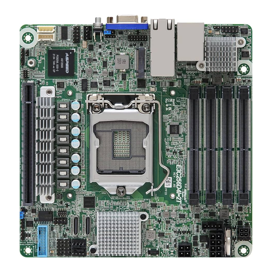
Page 14: Motherboard Layout
DDR4_B1 (64 bit, 260-pin module) PSU_SMB1 Intel X550 DDR4_A2 (64 bit, 260-pin module) ATX12V2 DDR4_A1 (64 bit, 260-pin module) USB 3.2 Gen1 T: USB_1 IPMI_LAN SATAPWR1 B: USB_2 E3C256D4I-2T Super RoHS CLRMOS1 LAN2 LAN1 (NCSI) M2_1 Intel C256 SPI_TPM_J1 CHASSIS_ID0... - Page 15 E3C256D4I-2T Description 2 x 260-pin DDR4 SO-DIMM Slots (DDR4_A1, DDR4_B1) 2 x 260-pin DDR4 SO-DIMM Slots (DDR4_A2, DDR4_B2) ATX 4-PIN Power Connector (ATX4PIN1) ATX 12V Power Connector (ATX12V2) PSU SMBus (PSU_SMB1) SATA Power Connector (SATAPWR1) Clear CMOS Pad (CLRMOS1) Front Fan Connector (FAN2)
-
Page 16: Onboard Led Indicators
1.5 Onboard LED Indicators DDR4_B2 (64 bit, 260-pin module) DDR4_B1 (64 bit, 260-pin module) DDR4_A2 (64 bit, 260-pin module) DDR4_A1 (64 bit, 260-pin module) E3C256D4I-2T RoHS Item Status Description SB_PWR1_LED Green STB PWR ready FAN_LED2 FAN2 failed FAN_LED3 FAN3 failed... -
Page 17: I/O Panel
E3C256D4I-2T 1.6 I/O Panel No. Description No. Description USB 3.0 Ports (USB3_1_2) 10G LAN RJ-45 Port (LAN_2)** LAN RJ-45 Port (IPMI_LAN)* VGA Port (VGA1) 10G LAN RJ-45 Port (LAN_1)** UID Switch (UID1) LAN Port LED Indications *There are two LEDs on each LAN port. Please refer to the table below for the LAN port LED indications. - Page 18 **There are two LEDs on each LAN port. Please refer to the table below for the LAN port LED indications. ACT/LINK LED SPEED LED LAN Port LAN Port LED Indications Activity / Link LED Speed LED Status Description Status Description No Link 100Mbps connection or no link...
-
Page 19: Block Diagram
E3C256D4I-2T 1.7 Block Diagram DDR4 SODIMM Channel A INTEL 1DPC for 2900/ PCI-E X16 SLOT 7 2DPC for 2133 Processor DDR4 SODIMM M.2_1 PCI-E Gen4 BUS LGA-1200 Pin Socket Channel B 1DPC for 2900/ 2DPC for 2133 HSIO 18-21 PCIE3.0 / SATA 3... -
Page 20: Chapter 2 Installation
Chapter 2 Installation This is a mini ITX form factor (6.7'' x 6.7'', 17.02 cm x 17.02 cm) motherboard. Before you install the motherboard, study the configuration of your chassis to ensure that the motherboard fits into it. Make sure to unplug the power cord before installing or removing the motherboard. Failure to do so may cause physical injuries to you and damages to motherboard components. -
Page 21: Installing The Cpu
E3C256D4I-2T 2.3 Installing the CPU 1. Before you insert the 1151-Pin CPU into the socket, please check if the PnP cap is on the socket, if the CPU surface is unclean, or if there are any bent pins in the socket. Do not force to insert the CPU into the socket if above situation is found. - Page 22 Please save and replace the cover if the processor is removed. The cover must be placed if you wish to return the motherboard for after service.
-
Page 23: Installing The Cpu Fan And Heatsink
E3C256D4I-2T 2.4 Installing the CPU Fan and Heatsink... -
Page 24: Installation Of Memory Modules (Dimm)
2.5 Installation of Memory Modules (DIMM) This motherboard provides four 260-pin DDR4 (Double Data Rate 4) DIMM slots. 1. It is not allowed to install a DDR, DDR2 or DDR3 memory module into a DDR4 slot; otherwise, this motherboard and DIMM may be damaged. 2. - Page 25 E3C256D4I-2T...
-
Page 26: Expansion Slot (Pci Express Slot)
2.6 Expansion Slot (PCI Express Slot) There is a PCI Express slot on this motherboard. PCIE slot: PCIE7 (PCIe 4.0 x16 slot) is used for PCI Express x16 lane width cards. Slot Generation Mechanical Electrical Source PCIE 7 Installing an expansion card Step 1. -
Page 27: Jumper Setup
E3C256D4I-2T 2.7 Jumper Setup The illustration shows how jumpers are setup. When the jumper cap is placed on the pins, the jumper is “Short”. If no jumper cap is placed on the pins, the jumper is “Open”. The illustration shows a 3-pin jumper whose pin1 and pin2 are “Short”... -
Page 28: Onboard Headers And Connectors
2.8 Onboard Headers and Connectors Onboard headers and connectors are NOT jumpers. Do NOT place jumper caps over these headers and connectors. Placing jumper caps over the headers and connectors will cause permanent damage to the motherboard. System Panel Header C onnec t t he power sw itch, PLED+ PLED-... - Page 29 E3C256D4I-2T +5VSB ATX_PG ATX 4-PIN Power The motherboard provides one Connector 4-pin power/signal connector (4-pin ATX4PIN1 which is a required input for ATX power source. (ATX 24pin-to-4pin) PSON# (see p.6, No. 3) When using ATX power, it is necessary to use a 24pin-to-...
- Page 30 ATX 12V Power The motherboard provides one Connector 8-pin 12V power connector (8-pin ATX12V2) which is a required input for (see p.6, No. 4) either DC-IN 12V or ATX +12V power source. When using ATX power, it is necessary to use a 24pin-to- 4pin power cable to connect between the 24pin power connector of PSU and the...
- Page 31 E3C256D4I-2T SPI TPM Header This connector supports SPI_DQ3 SPI_DQ2 (13-pin SPI_TPM_J1) Trusted Platform Module SPI_CS0 SPI_PWR Dummy SPI_MISO (see p.6, No. 25) (TPM) system, which can RSMRST# securely store keys, digital SPI_MOSI RST# SPI_TPM_CS# certificates, passwords, and TPM_PIRQ data. A TPM system also helps...
- Page 32 Clear CMOS Pad CLRMOS1 allows you to clear (CLRMOS1) the data in CMOS. To clear (see p.6, No. 7) CMOS, take out the CMOS battery and short the Clear CMOS Pad. PSU SMBus PSU SMBus monitors the SMBCLK SMBDATA (PSU_SMB1) status of the power supply, fan ALERT (see p.6, No.
-
Page 33: Atx Psu / Dc-In Power Connections
E3C256D4I-2T 2.9 ATX PSU / DC-IN Power Connections This motherboard supports both +12V DC and ATX power input. Please refer to the table below for the required connections between the motherboard and the power supply. Connector DC-IN ATX PSU 12V 8pin... -
Page 34: Unit Identification Purpose Led/Switch
2.10 Unit Identification purpose LED/Switch With the UID button, You are able to locate the server you’re working on from behind a rack of servers. Unit Identification When the UID button on the purpose LED/Switch front or rear panel is pressed, (UID1) the front/rear UID blue LED indicator will be turned on. -
Page 35: Dual Lan And Teaming Operation Guide
E3C256D4I-2T 2.12 Dual LAN and Teaming Operation Guide Dual LAN with Teaming enabled on this motherboard allows two single connections to act as one single connection for twice the transmission bandwidth, making data transmission more effective and improving the quality of transmission of distant images. - Page 36 2.13 M.2 SSD Module Installation Guide (M2_1) The M.2 Socket (M2_1, Key M) supports type 2280 M.2 PCI Express module up to Gen4 x4 (64GT/s). Installing the M.2 SSD Module Step 1 Prepare a M.2 SSD module and the screw. Step 2 Gently insert the M.2 SSD module into the M.2 slot.
-
Page 37: Chapter 3 Uefi Setup Utility
E3C256D4I-2T Chapter 3 UEFI Setup Utility 3.1 Introduction This section explains how to use the UEFI SETUP UTILITY to configure your system. The UEFI chip on the motherboard stores the UEFI SETUP UTILITY. You may run the UEFI SETUP UTILITY when you start up the computer. Please press <F2> or <Del> during the Power-On-Self-Test (POST) to enter the UEFI SETUP UTILITY;... -
Page 38: Navigation Keys
3.1.2 Navigation Keys Please check the following table for the function description of each navigation key. Navigation Key(s) Function Description Moves cursor left or right to select Screens Moves cursor up or down to select items + / - To change option for the selected items <Tab>... -
Page 39: Main Screen
E3C256D4I-2T 3.2 Main Screen Once you enter the UEFI SETUP UTILITY, the Main screen will appear and display the system overview. The Main screen provides system overview information and allows you to set the system time and date. Because the UEFI software is constantly being updated, the following UEFI setup screens and descriptions for reference purpose only, and may vary from the latest BIOS and do not exactly match what you see on your screen. - Page 40 3.2.1 Motherboard Information Press [Enter] to view the information of the motheboard. 3.2.2 Processor Information Press [Enter] to view the information of the processor.
- Page 41 E3C256D4I-2T 3.2.3 Memory Information Press [Enter] to view the information of the memory.
-
Page 42: Advanced Screen
3.3 Advanced Screen In this section, you may set the configurations for the following items: CPU Configuration, DRAM Configuration, Chipset Configuration, Storage Configuration, NVMe Configura- tion, ACPI Configuration, Super IO Configuration, Serial Port Console Redirection, H/W Monitor, Intel SPS Configuratio, Driver Health, Network Stack Configuration, Tls Auth Configuration and Instant Flash. -
Page 43: Cpu Configuration
E3C256D4I-2T 3.3.1 CPU Configuration SGX settings Use this item to configure SGX settings. Software Guard Extensions (SGX) Use this item to enable or disable Software Controlled Software Guard Extensions (SGX). When this is enabled, you will see the following items. - Page 44 PRMRR Size Use this item to set the PRMRR Size (Decimal). Optio Enable/Disable SGX Debug Mode SGX Debug Mode based on Debug Mode support in a CPU stepping. It can be configured only if Debug Interface is enabled and locked. Intel Hyper Threading Technology (Supported depending on your CPU) Intel Hyper Threading Technology allows multiple threads to run on each core, so that the...
- Page 45 E3C256D4I-2T cache line. Enable for better performance. Use this to enable or disable CPU Advanced Encryption Standard instructions. Boot Performance Mode Use this to item to select the performance state that the BIOS will set starting from reset vector. Intel SpeedStep Technology Intel SpeedStep technology allows processors to switch between multiple frequencies and voltage points for better power saving and heat dissipation.
-
Page 46: Dram Configuration
3.3.2 DRAM Configuration DRAM Frequency If [Auto] is selected, the motherboard will detect the memory module(s) inserted and assign the appropriate frequency automatically. -
Page 47: Chipset Configuration
E3C256D4I-2T 3.3.3 Chipset Configuration Intel IGFX Keep IGFX enabled based on the setup options. Onboard VGA Use this to enable or disable the Onboard VGA functions. The default value is [Enabled]. Onboard LAN1 and LAN2 Use this to enable or disable the Onboard LAN1 and LAN2 function. The default value is [Enabled]. - Page 48 PCIE Link Width PCIE7 Link Width This allows you to select PCIe Link Width. The default value is [x16].. PCIE Link Speed PCIE7 Link Speed This allows you to select PCIE Link Speed. The default value is [Auto]. OCU1 Link Speed This allows you to select PCIE Link Speed.
-
Page 49: Storage Configuration
E3C256D4I-2T 3.3.4 Storage Configuration Hard Disk S.M.A.R.T. S.M.A.R.T. stands for Self-Monitoring, Analysis, and Reporting Technology. It is a monitoring system for computer hard disk drives to detect and report on various indicators or reliability. -
Page 50: Nvme Configuration
3.3.5 NVMe Configuration The NVMe Configuration displays the NVMe controller and Drive information. -
Page 51: Acpi Configuration
E3C256D4I-2T 3.3.6 ACPI Configuration PCIE Devices Power On This allows the system to be waked up by a PCIE device and enable wake-on-LAN. Ring-In Power On This allows the system to be waked up by onboard COM port modem Ring-In signals. -
Page 52: Super Io Configuration
3.3.7 Super IO Configuration Serial Port 1 Configuration Use this item to set parameters of Serial Port 1 (COM1). Serial Port Use this item to enable or disable the serial port. Change Settings Use this item to select an optimal setting for Super IO device. SOL Configuration Use this item to set SOL configuration. -
Page 53: Serial Port Console Redirection
E3C256D4I-2T 3.3.8 Serial Port Console Redirection COM1 / SOL Console Redirection Use this option to enable or disable Console Redirection. If this item is set to Enabled, you can select a COM Port to be used for Console Redirection. Console Redirection Settings Use this option to configure Console Redirection Settings, and specify how your computer and the host computer to which you are connected exchange information. - Page 54 Bits Per Second Use this item to select the serial port transmission speed. The speed used in the host computer and the client computer must be the same. Long or noisy lines may require lower transmission speed. The options include [9600], [19200], [57600] and [115200]. Data Bits Use this item to set the data transmission size.
- Page 55 E3C256D4I-2T Redirect After POST When Bootloader is selected, then Legacy Console Redirection is disabled before booting to legacy OS. When Always Enable is selected, then Legacy Console Redirection is enabled for legacy OS. Default setting for this option is set to Always Enable.
-
Page 56: H/W Monitor
3.3.9 H/W Monitor In this section, it allows you to monitor the status of the hardware on your system, includ- ing the parameters of the CPU temperature, motherboard temperature, CPU fan speed, chassis fan speed, and the critical voltage. -
Page 57: Intel Sps Configuration
E3C256D4I-2T 3.3.10 Intel SPS Configuration SPS screen displays the Intel SPS Configuration information, such as Operational Firmware Version and Firmware State. -
Page 58: Driver Health
3.3.11 Driver Health Intel(R) 10GbE Driver 7.8.13 x64 Healthy This provides health status for the drivers/controllers. Intel(R) 10GbE Driver 7.8.13 x64 Healthy This provides health status for the drivers/controllers. -
Page 59: Tls Auth Configuration
E3C256D4I-2T 3.3.12 Tls Auth Configuration Server CA Configuration Press <Enter> to configure Server CA. Client Cert Configuration Press <Enter> to configure Client Cert. -
Page 60: Instant Flash
3.3.13 Instant Flash Instant Flash is a UEFI flash utility embedded in Flash ROM. This convenient UEFI update tool allows you to update system UEFI without entering operating systems ® first like MS-DOS or Windows . Just save the new UEFI file to your USB flash drive, floppy disk or hard drive and launch this tool, then you can update your UEFI only in a few clicks without preparing an additional floppy diskette or other compli- cated flash utility. -
Page 61: Server Mgmt
E3C256D4I-2T 3.4 Server Mgmt Wait For BMC Wait For BMC response for specified time out. BMC starts at the same time when BIOS starts during AC power ON. It takes around 90 seconds to initialize Host to BMC interfaces. FRB-2 Timer Use this item to enable or disable FRB-2 timer (POST timer). - Page 62 OS Wtd Timer Timeout Enter the value Between 1 to 30 min for OS Boot Watchdog Timer Expiration. Not available if OS Boot Watchdog Timer is disabled. OS Wtd Timer Policy Configure how the system should respond if the OS Boot Watchdog Timer expires. Not available if OS Boot Watchdog Timer is disabled.
-
Page 63: Bmc Network Configuration
E3C256D4I-2T 3.4.1 BMC Network Configuration Bonding Setting Use this item to enable or disable bonding. If you want to enable bonding, please enable all Lan channel first. BMC Out of band Access Use this item to enable or disable BMC Out of band Access. - Page 64 The default login information for the IPMI web interface is: Username: admin Password: admin For more instructions on how to set up remote control environment and use the IPMI man- agement platform, please refer to the IPMI Configuration User Guide or go to the Support website at: http://www.asrockrack.com/support/faq.asp VLAN Enabled/Disabled Virtual Local Area Network.
-
Page 65: System Event Log
E3C256D4I-2T 3.4.2 System Event Log SEL Components Change this to enable ro disable event logging for error/progress codes during boot. Erase SEL Use this to choose options for earsing SEL. When SEL is Full Use this to choose options for reactions to a full SEL. -
Page 66: Bmc Tools
3.4.4 BMC Tools KCS Control Select this KCS interface state after POST end. If [Enabled] us selected, the BMC will remain KCS interface after POST stage. If [Disabled] is selected, the BMC will disable KCS interface after POST stage Restore AC Power Loss This allows you to set the power state after an unexpected AC/power loss. -
Page 67: Security
E3C256D4I-2T 3.5 Security In this section, you may set or change the supervisor/user password for the system. For the user password, you may also clear it. Supervisor Password Set or change the password for the administrator account. Only the administrator has authority to change the settings in the UEFI Setup Utility. -
Page 68: Key Management
3.5.1 Key Management In this section, expert users can modify Secure Boot Policy variables without full authenti- cation. Factory Key Provision Install factory default Secure Boot keys after the platform reset and while the System is in Setup mode. Install Default Secure Boot Keys Please install default secure boot keys if it’s the first time you use secure boot. - Page 69 E3C256D4I-2T Remove 'UEFI CA' from DB Device Guard ready system must not list ‘Microsoft UEFI CA’ Certificate in Autho- rized Signature database (db). Restore DB defaults Restore DB variable to factory defaults. Platform Key(PK) Enroll Factory Defaults or load certificates from a file: 1.
- Page 70 1. Public Key Certificate in: a) EFI_SIGNATURE_LIST b) EFI_CERT_X509 (DER encoded) c) EFI_CERT_RSA2048 (bin) d) EFI_CERT_SHA256, 384, 512 2. Authenticated UEFI Variable 3. EFI PE/COFF Image(SHA256) Key Source: Factory, External, Mixed Forbidden Signatures Enroll Factory Defaults or load certificates from a file: 1.
- Page 71 E3C256D4I-2T OsRecovery Signatures Enroll Factory Defaults or load certificates from a file: 1. Public Key Certificate in: a) EFI_SIGNATURE_LIST b) EFI_CERT_X509 (DER encoded) c) EFI_CERT_RSA2048 (bin) d) EFI_CERT_SHA256, 384, 512 2. Authenticated UEFI Variable 3. EFI PE/COFF Image(SHA256) Key Source: Default, External, Mixed, Test...
- Page 72 3.6 Boot Screen In this section, it will display the available devices on your system for you to configure the boot settings and the boot priority. Boot Option #1 Use this item to set the system boot order. Boot Option #2 Use this item to set the system boot order.
- Page 73 E3C256D4I-2T UEFI USB Drive BBS Priorities (This item appears when an USB device is installed.) Specifies the Boot Device Priority sequence from available UEFI USB Drives. UEFI NVME Drive BBS Priorities (This item appears when a NVME device is installed.) Specifies the Boot Device Priority sequence from available UEFI USB Drives.
-
Page 74: Event Logs
3.7 Event Logs Change Smbios Event Log Settings This allows you to configure the Smbios Event Log Settings. When entering the item, you will see the followings: Smbios Event Log Use this item to enable or disable all features of the SMBIOS Event Logging during system boot. -
Page 75: Exit Screen
E3C256D4I-2T 3.8 Exit Screen Save Changes and Exit When you select this option, the following message “Save configuration changes and exit setup?” will pop-out. Press <F10> key or select [Yes] to save the changes and exit the UEFI SETUP UTILITY. -
Page 76: Chapter 4 Software Support
4.3 Contact Information If you need to contact ASRock Rack or want to know more about ASRock Rack, welcome to visit ASRock Rack’s website at http://www.ASRockRack.com; or you may contact your... -
Page 77: Chapter 5 Troubleshooting
E3C256D4I-2T Chapter 5 Troubleshooting 5.1 Troubleshooting Procedures Follow the procedures below to troubleshoot your system. Always unplug the power cord before adding, removing or changing any hardware com- ponents. Failure to do so may cause physical injuries to you and damages to motherboard components. - Page 78 1. Verify if the battery on the motherboard provides ~3VDC. Install a new battery if it does not. 2. Confirm whether your power supply provides adaquate and stable power. Other problems... 1. Try searching keywords related to your problem on ASRock Rack’s FAQ page: http://www.asrockrack.com/support...
-
Page 79: Technical Support Procedures
E3C256D4I-2T 5.2 Technical Support Procedures If you have tried the troubleshooting procedures mentioned above and the problems are still unsolved, please contact ASRock Rack’s technical support with the following information: 1. Your contact information 2. Model name, BIOS version and problem type. - Page 80 Contact Information If you need to contact ASRock Rack or want to know more about ASRock Rack, you’re welcome to visit ASRock Rack’s website at http://www.asrockrack.com; or you may contact your dealer for further information. For technical questions, please submit a support request form at https://event.asrockrack.com/tsd.asp ASRock Rack Incorporation e-mail: ASRockRack_sales@asrockrack.com...