Table of Contents
Advertisement
Quick Links
Advertisement
Table of Contents

Related Manuals for Neilsen CT1056


Summary of Contents for Neilsen CT1056
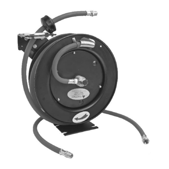
- Page 1 AUTO RETRACTABLE AIR HOSE REEL 3/8” x 30FT CT1056 ORIGINAL INSTRUCTIONS SAVE THESE INSTRUCTIONS AND PRECAUTIONS. READ ALL PRECAUTONS AND INSTRUCTIONS BEFORE USE. Cannon Tools Limited Address: 20 Station Road, Rowley Regis, West Midlands, B65 0JU.U.K.
-
Page 2: Ec Declaration Of Conformity
In case of alteration of the machine, not agreed upon by us, this declaration will lose its validity. Product description: AUTO RETRACTABLE AIR HOSE REEL Model: CT1056 Applicable EC Directives: EC Machinery Directive 2006/42/EC Harmonized standards EN ISO 12100:2010 20 Station Road, Rowley Regis, West Midlands, B65 0JU.U.K. -
Page 3: Specification
1. SPECIFICATION Model: CT1056 Air hose size: 3/8” x 30ft Air adaptor: 3/8” Max. Working pressure: 300PSI 2. IMPORTANT SAFETY INFORMATION WARNING - When using tools, basic precautions should always be followed, including the following: To reduce the risks of electric shock, fire, and injury to persons, read all the instructions before using the tool. - Page 4 Tool Use and Care 1.Do not force the tool. Use the correct tool for the application. The correct tool will do the job better and safer at the rate for which the tool is designed. 2.Disconnect the tool from the air source before making any adjustments, changing accessories, or storing the tool.
-
Page 5: Technical Description
3. TECHNICAL DESCRIPTION 4. UNPACKING AND CHECKING Carefully remove the product from the packaging and examine it for any sign of damage that may have happened during shipping. Lay the contents out and check them against the parts shown below. If any part is damaged or missing; please contact the seller and do not attempt to use the product. - Page 6 5. TYPICAL COMPRESSED AIR SYSTEM 6. OPERATING AIR HOSE REEL BEFORE MOUNTING AIR HOSE REEL, please take a few minutes to understand how the reel works. Practice operating the hose reel a few times, pulling hose out and retracting it back onto reel. This will familiarize you with basic functions and can help you understand where best to mount the air hose reel.
- Page 7 MOUNTING HOSE REEL Choosing a Location DO NOT MOUNT HOSE REEL OUTDOORS OR ON VEHICLE. This hose reel is not designed to resist constant exposure to weather or continuous vibration. Mount under cover in an area not directly exposed to weather. Reel can be mounted on the floor, ceiling, or wall, wherever it is convenient.
- Page 8 ADJUSTING THE GUIDE ARM 2. Remove the four bolts connecting 1. Pull out 3-4 feet of hose and guide arm to base. lock reel in position. 3. Rotate guide arm in 90 increments to desired position. Replace four bolts and tighten.
- Page 9 GENERAL OPERATING INSTRUCTIONS 1. Slowly pull hose from reel to desired length. A ratcheting mechanism inside reel makes a short series of clicking sounds every half revolution of reel. 2. To lock reel in position, listen for clicking sounds as hose is slowly pulled from reel.When reel clicks,stop pulling hose.
-
Page 10: Cleaning, Maintenance, And Lubrication
7. MAINTENANCE WARNING • To prevent serious injury: Detach air supply from this product before performing any inspection, maintenance, or cleaning procedures. • To prevent serious injury from tool failure: Do not use damaged equipment. If abnormal noise, vibration, or leaking air occurs, have the problem corrected before further use. - Page 11 8. SYMBOLS In this manual and/or on the machine the following symbols are used: Denotes risk of personal injury, loss of life or damage to the tool in case of non-observance of the instructions in this manual. Wear hearing protection. Wear safety goggles.
- Page 12 10. EXPLODED VIEW & PART LISTS Part Description Part Description Part Description Spring Canister Lock Washer Roller Guide Bracket Assembly Drum(air inlet side) Hose Stopper Assembly Drum (mounting Bolt Ratchet Locking bracket side) Gear Mounting Bracket Spacing Washer Guide Arm Clamp Retaining Ring Air lnlet Valve Body...