Advertisement
Quick Links
ALESIS
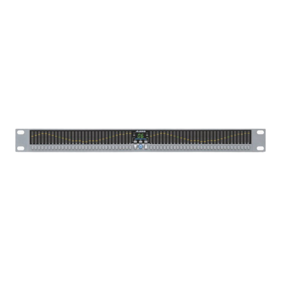
DEQ230 (ME2)
Service Manual
P/N: 8-31-0103-A
ATTENTION!
THIS DOCUMENT CONTAINS SENSITIVE
PROPRIETARY INFORMATION. ALL
RECIPIENTS MUST HAVE A CURRENT NON-
DISCLOSURE AGREEMENT ON FILE WITH
ALESIS DISTRIBUTION, LLC.
DO NOT DISTRIBUTE THIS DOCUMENT IN
ELECTRONIC FORM
The information in this document contains privileged and confidential information. It is
intended only for the use of those authorized by Alesis. If you are not the authorized,
intended recipient, you are hereby notified that any review, dissemination, distribution or
duplication of this document is strictly prohibited. If you are not authorized, please
contact Alesis and destroy all copies of this document. You may contact Alesis at
support@Alesis.com.
Copyright © 2002 Alesis Distribution, LLC
Confidential
Alesis Service Manual
8-31-0103-A
Advertisement

Related Manuals for Alesis DEQ230


Summary of Contents for Alesis DEQ230
- Page 1 The information in this document contains privileged and confidential information. It is intended only for the use of those authorized by Alesis. If you are not the authorized, intended recipient, you are hereby notified that any review, dissemination, distribution or duplication of this document is strictly prohibited.
- Page 2 Only Service Centers authorized by Alesis in writing are authorized to perform service and repairs covered by an Alesis warranty (if any), and transfer of the Manual to you does not authorize you to be an authorized Service Center. Therefore, if you perform, or if the Manual is used to perform, any service or repairs...
- Page 3 ALL REPAIRS DONE BY ANY ENTITY OTHER THAN AN AUTHORIZED ALESIS SERVICE CENTER SHALL BE SOLELY THE RESPONSIBILITY OF THAT ENTITY, AND ALESIS SHALL HAVE NO LIABILITY TO THAT ENTITY OR TO ANY OTHER PARTY FOR ANY REPAIRS BY THAT ENTITY.
- Page 4 The product is exposed to water or excessive moisture, The AC power supply plug or cord is damaged, The product shows an inappropriate change in performance or does not operate normally, or The enclosure of the product has been damaged. Confidential Alesis Service Manual 8-31-0103-A...
-
Page 5: General Troubleshooting
° Self Test - Alesis products that utilize microprocessor control contain built in test software which exercises many of the units' primary circuit functions. Self test should always be done following any repair to ensure basic functionality. -
Page 6: Specification
SERVICE MANUAL MODEL:DEQ-230 31.5 1.25K 1.6k 2.5k 3.15K 6.3k 12.5k 31.5 31 5 1.25k 1.6k 2.5k 3.15k 6.3k 12.5k SPECIFICATION Audio Input Key features: Input Connectors: 2 Impedance-Balanced 1/4”TRS • Up/down data buttons that serve dual purpose—to Jacks increment/decrement gain on a selected frequency Nominal Input Level: -10dBV (-15dBFS) band or to select a preset curve from memory... -
Page 7: Disassembly Procedures
DISASSEMBLY PROCEDURES 1. REMOVAL OF TOP COVER / FRONT PAREL (Fig1) (A) TAKE OUT THE 3PC SCREWS FROM WHICH THE REAR PAREL. (B) TAKE OUT THE 3PC SCREWS FROM WHICH THE TOP PAREL. (C) TAKE OUT THE 3PC SCREWS FROM WHICH THE BOTTOM CHASSIS. - Page 8 DISASSEMBLY PROCEDURES 3.REMOVAL OF FRONT PAREL P.C.B (Fig.3) (A.) REMOVE THE 3PC OF SUB-PANEL. Fig.3...
- Page 9 WIRING DIAGRAM (US/EU/UK/AUS NZ)
- Page 10 Packing Diagram (US/EU/AK/AUS/NZ)
- Page 11 Exploded View (US/AU/UK/AUS/NZ)
-
Page 12: Parts List
PARTS LIST (US/EU/UK/AUS NZ) NO. PARTS NAME PARTS NO. Q'TY SCREW SC0306AICI TOP COVER MT133010101 CUSHION RUBBER RU1304401 RACK EAR MT130440201 FRONT PANEL PT133000101 LENS NP613ALE01 BOTTOM CHASSIS MT133030101 MAIN P.C.B TWPC01C07401 SUB-PANEL MT1304401 10 ASSY FRONT PAREL PCB 9-79-0262 11 LED FRAME PT1304301 12 RUBBER KEYPAD... -
Page 13: Functionality Test
Panel Sub-Assembly and hold these buttons during Step 2. When started in this manner, the unit will enter Factory Test Mode. Plug the P3 type Alesis Power Supply into a power source and the barrel jack into the DUT Power In jack. - Page 14 Failure of this inspection indicate a serious problem with current firmware for production. The DUT cannot continue further testing, and the Alesis Engineers listed at the top of this document should be asked for current software or current version of this document before continuing production.
- Page 15 OR failed LED. Be sure to verify that BOTH LEDs turn on at the same time. Either type of problem indicate the test has FAILED. Failure of this inspection indicate that the DUT cannot continue further testing. Confidential Alesis Service Manual 8-31-0103-A...
- Page 16 Problems with no response or flickering LEDs indicates poor or failed switch, OR failed LED. Either type of problem indicate the test has FAILED. Failure of this inspection indicate that the DUT cannot continue further testing. Confidential Alesis Service Manual 8-31-0103-A...
- Page 17 Failure of this inspection indicate that the DUT cannot continue further testing. Unplug the power supply to the DUT. Then unplug all other cabling to the DUT. This is the end of the Front Panel Sub-Assembly electrical test. Confidential Alesis Service Manual 8-31-0103-A...
- Page 18 Make sure that all artwork is clear and correctly aligned. Quickly plug the unit into an Alesis P3 type power supply to ensure LEDs light and proper startup screen appears. While the LEDs are on, check to make sure that the front lens is clear and working as anticipated.
-
Page 19: Power Test
DUT is ready for testing. Continue with Power Test. Power Test Plug the P3 type Alesis Power Supply into a power source and the barrel jack into the Rear Panel Power In jack. Verify that the front panel LEDs show normal power up message, “DEQ”... - Page 20 Press the LINK/EXIT and BYPASS buttons on the DUT and hold these buttons during Step 2. When started in this manner, the unit will enter Factory Test Mode. Plug the P3 type Alesis Power Supply into a power source and the barrel jack into the DUT Power In jack.
- Page 21 Failure of this inspection indicate a serious problem with current firmware for production. The DUT cannot continue further testing, and the Alesis Engineers listed at the top of this document should be asked for current software or current version of this document before continuing production.
- Page 22 FAILED. Problems with the appearance of the LEDs also indicates the test has FAILED. Failure of this inspection indicate that the DUT cannot continue further testing. Confidential Alesis Service Manual 8-31-0103-A...
- Page 23 Failure of this inspection indicate that the DUT cannot continue further testing. Unplug the power supply to the DUT. Then unplug all other cabling to the DUT. This is the end of the Final Assembly QC test. Confidential Alesis Service Manual 8-31-0103-A...
-
Page 24: Items Required
Press the UP and DOWN buttons on the DUT and hold these buttons during Step 2. When started in this manner, the unit will RESET. Plug the P3 type Alesis Power Supply into a power source and the barrel jack into the DUT Power In jack. - Page 25 ALESIS DEQ230 (ME2) BOM, SCHEMATIC, PCB FILES, ECN HISTORY Confidential Alesis Service Manual 8-31-0103-A...
- Page 26 STICKER BARCODE S/N ME2 PACKOUT 7-52-0040-B STICKER ETL/FCC/CE/C-TICK & CAUTION 9-10-0056 BEZEL DISPLAY 3.3 THICK CLEAR ME2 PACKOUT 7-51-1219-B SHEET "WELCOME TO ALESIS FAMILY" 5 x 8" 7-91-1002 GEL SILICA 5G PACKET 7-80-0310 ENDCAP CARDBOARD/PRESSBOARD ME2 7-80-0311-A GIFT BOX ME2 7-80-0312-A...
- Page 27 WASHER FLAT #4 ZINC 0.25"OD 5-01-0029 U2 U5 NUT HEX 4-40 5-02-4402 9-40-0261-3 PCB REAR PANEL ME2 - REV 3 HEAT SINK, BLACK - ME2 INSTALL WITH U5 9-03-0142 LABOR LABOR 9-79-0262 ASSY PCB FRONT PANEL ME2 0-17-0101 RES CHIP ARRAY 4 x 100 OHM 1/16W 5% ISOLATED c-c=0.8mm R1-2 R19 0-17-0102 RES CHIP ARRAY 4 X 1K OHM 1/16W 5% ISOLATED c-c=0.8mm SMD...
- Page 28 ME2FP208a.sch-1 - Tue Sep 17 13:07:36 2002...
- Page 29 ME2FP208a.sch-2 - Tue Sep 17 13:07:47 2002...
- Page 30 ME2FP208a.sch-3 - Tue Sep 17 13:07:56 2002...
- Page 31 ME2FP208a.sch-4 - Tue Sep 17 13:08:05 2002...
- Page 32 ME2FP208a.sch-5 - Tue Sep 17 13:08:20 2002...
- Page 33 ME2FP208a.sch-6 - Tue Sep 17 13:08:28 2002...