ADC PAIRGAIN HiGain HDSL2 Manual
Hide thumbs
Also See for PAIRGAIN HiGain HDSL2:
- Manual (80 pages) ,
- Quick installation manual (7 pages) ,
- User manual (66 pages)

Related Manuals for ADC PAIRGAIN HiGain HDSL2


Summary of Contents for ADC PAIRGAIN HiGain HDSL2
- Page 1 HiGain HiGain HiGain HDSL2 Line Unit H2TU-C-231 List 1E Part Number: 150-2404-15 CLEI Code: VACH4VYC...
- Page 2 Contents herein are current as of the date of publication. ADC reserves the right to change the contents without prior notice. In no event shall ADC be liable for any damages resulting from loss of data, loss of use, or loss of profits, and ADC further disclaims any and all liability for indirect, incidental, special, consequential or other similar damages.
- Page 3 152-231-115-03, Issue 03 Using This Technical Practice SING ECHNICAL RACTICE The following conventions are used in this manual: • Monospace type indicates screen text. • Keys you press are indicated by small icons such as ENTER . Key combinations to be pressed simultaneously are indicated with a plus sign as follows: CTRL •...
- Page 4 Inspecting Shipment 152-231-115-03, Issue 03 April 21, 2000 H2TU-C-231...
-
Page 5: Table Of Contents
152-231-115-03, Revision 03 Table of Contents ABLE OF ONTENTS Overview ____________________________________________________________________________ 1 Features ..............................1 Compatibility .............................2 Applications ............................2 HiGain Regenerators..........................3 Front Panel __________________________________________________________________________ 4 Installation___________________________________________________________________________ 9 Verification ............................10 Verification without a Downstream Device ..............10 Verification with a Downstream Device ................10 Provisioning Requirements ......................11 Provisioning_________________________________________________________________________ 12 Using the MODE and SEL Buttons ....................12... - Page 6 Table of Contents 152-231-115-03, Revision 03 Alarm History at the HDSL2 Interface ................42 Using the Event Log to Track System Events................. 43 Testing _____________________________________________________________________________ 45 Front-Panel System Alarms......................45 Alarm Option for Digital Loop Carrier (DLC) Feed ............46 Retiring System Alarms ....................
- Page 7 152-231-115-03, Revision 03 Table of Contents H2TU-C-231 List 1E April 21, 2000...
- Page 8 List of Figures 152-231-115-03, Revision 03 IST OF IGURES 1. HDSL2 System Model ..........................3 2. H2TU-C-231 List 1E Front Panel......................... 4 3. Installing the H2TU-C-231List 1E into a Shelf .................... 9 4. Logon Screen .............................. 15 5. Configuration Menu - Date and Time......................16 6.
- Page 9 152-231-115-03, Revision 03 List of Tables IST OF ABLES 1. Front-panel Description..........................5 2. Front-panel Display Messages ........................6 3. Navigational Keys for the HiGain HDSL2 Maintenance Terminal Screens..........14 Logon Screen Menus...........................15 5. H2TU-C-231 List 1E Standard Config Screen Options................20 6. H2TU-C-231 List 1E PairGain Config Screen Options................21 7.
- Page 10 List of Tables 152-231-115-03, Revision 03 April 21, 2000 H2TU-C-231 List 1E...
-
Page 11: Overview
High- bit-rate Digital Subscriber Line 2 (HDSL2). ADC products are fully compliant with the HDSL2 standard. Providing full-rate T1 access using just a single copper pair, HDSL2 is a cost-effective solution that offers an open architecture. -
Page 12: Compatibility
Overview 152-231-115-03, Revision 03 • Payload (PL) and HiGain (HG) loopback source identification • Network Management and Administration (NMA) interface • Margin Alarm (MAL) threshold OMPATIBILITY The H2TU-C-231 is designed to mount in 220 mechanics shelves. For a list of compatible shelves see “Appendix C - Compatibility”... -
Page 13: Higain Regenerators
152-231-115-03, Revision 03 Overview Figure 1. HDSL2 System Model EGENERATORS For applications without regenerators (doublers), the H2TU-C-231 is directly connected to an H2TU-R remote unit by one HDSL2 cable pair. The H2TU-C-231 List 1E is compatible with all HiGain H2TU-Rs. For applications with regenerators, one to two regenerators may be used in the HDSL2 loop between the H2TU-C and H2TU-R. -
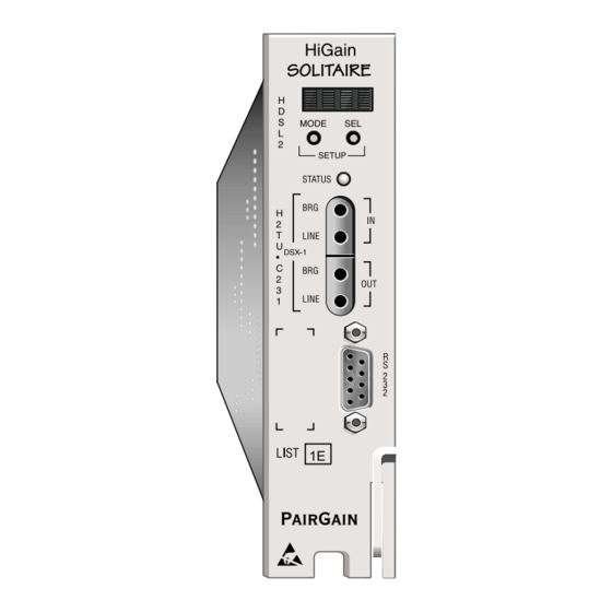
Page 14: Front Panel
Front Panel 152-231-115-03, Revision 03 RONT ANEL Figure 2 shows the H2TU-C-231 List 1E front panel. Table 1 on page 5 describes the front-panel components. For pinout diagrams of the H2TU-C card-edge connector and craft port, refer to “Appendix A - Specifications” on page Figure 2. - Page 15 152-231-115-03, Revision 03 Front Panel Table 1. Front-panel Description Front-panel Feature Function Front-panel display Displays four-character status, provisioning, and alarm system messages. The front-panel display illuminates when power is initially applied. To conserve power, the display only remains on for 5 minutes. Using the MODE or SEL buttons reactivates the display and restarts the 5-minute timer.
-
Page 16: Front-Panel Display Messages
Front Panel 152-231-115-03, Revision 03 Table 2 lists the front-panel display messages. The three- or four-character display reports the code of a pertinent alarm, loopback, or diagnostic message and, in some cases, is followed by a second four-character message that modifies the first message with a value or current configuration setting. - Page 17 152-231-115-03, Revision 03 Front Panel Table 2. Front-panel Display Messages (Cont.) Message Full Name Description LOOPBACK MESSAGES CRGn Customer Regenerator n Loopback Signal from customer is looped back to the customer at H2RUn, where n is the number of the regenerator. CLOC Customer Local Loopback Signal from customer is looped back to the customer at the...
- Page 18 Front Panel 152-231-115-03, Revision 03 Table 2. Front-panel Display Messages (Cont.) Message Full Name Description Synchronization n Loop The transceivers of the two devices on Span n are trying to establish contact with each other, where n is the number of the span. SYSTEM INFORMATION MESSAGES CODE xxxx Line Code: AMI, B8ZS...
-
Page 19: Installation
Upon receipt of the equipment, inspect the contents for signs of damage. If the equipment has been damaged in transit, immediately report the extent of damage to the transportation company and to ADC. Figure 3. Installing the H2TU-C-231List 1E into a Shelf When installing an H2TU-C in a chassis, be sure to wear an antistatic wrist strap. -
Page 20: Verification
Installation 152-231-115-03, Revision 03 ERIFICATION Once the H2TU-C-231 is installed, verify that it is operating properly. To do this, monitor the following: • Status LED • Status messages reported by the front-panel display (Table 2 on page Verification without a Downstream Device If there is no downstream device installed: Verify that the H2TU-C powers up. -
Page 21: Provisioning Requirements
152-231-115-03, Revision 03 Installation ROVISIONING EQUIREMENTS Refer to “Provisioning” on page 12 for instructions on configuring and monitoring the H2TU-C-231. The H2TU-C-231 List 1E can be provisioned by using the MODE and SEL buttons on the front panel or by accessing the HiGain HDSL2 maintenance screens. -
Page 22: Provisioning
Provisioning 152-231-115-03, Revision 03 ROVISIONING There are two methods for provisioning: • Use the MODE and SEL buttons on the front panel of the H2TU-C to: – Set system options – Reset the H2TU-C to its factory default settings for system options –... -
Page 23: Resetting To Factory Default Values
152-231-115-03, Revision 03 Provisioning Resetting to Factory Default Values All user options for the H2TU-C-231 List 1E (Table 6 on page 21) can be set to the factory default values using the MODE and SEL buttons. To set the user options to their default values: Press the SEL button for 6 seconds until the following message appears: DFLT NO Press the SEL button while the DFLT NO message is displayed. -
Page 24: Using A Maintenance Terminal
Provisioning 152-231-115-03, Revision 03 SING A AINTENANCE ERMINAL Connecting to a Maintenance Terminal The craft port on the front panel allows you to connect the H2TU-C-231 to a maintenance terminal (ASCII terminal or PC running a terminal emulation program). Once connected to a maintenance terminal, you can access the maintenance, provisioning, and performance screens. -
Page 25: Logon Screen
Help Provides a glossary of terms used in the HiGain HDSL2 maintenance screens, a list of navigational keys, and ADC contact information. H2TU-C-231 List 1E April 21, 2000... -
Page 26: Provisioning Tasks
Provisioning 152-231-115-03, Revision 03 ROVISIONING ASKS After H2TU-C-231 is successfully installed, perform these basic provisioning tasks. • Set date and time • Set circuit ID numbers • Make any necessary configuration changes • Clear history, alarm, and event log screens to remove miscellaneous data during startup Setting Date and Time Monitor Performance... -
Page 27: Setting Circuit Id Numbers
152-231-115-03, Revision 03 Provisioning Setting Circuit ID Numbers The Inventory screen provides product information on all units in the system and allows the setting of the circuit and unit identification numbers. Monitor Performance Event Log Config Inventory Rlogon Help -------------------------- Product Information ---------------------------- Unit... -
Page 28: Making Changes To The System Configuration
Provisioning 152-231-115-03, Revision 03 Making Changes to the System Configuration The Config menu (Figure 7) allows you to make the following types of system configuration changes: • Standard options (Figure 8 on page • PairGain options (Figure 9 on page •... -
Page 29: Configuration Menu - Standard Options (Defaults Shown)
152-231-115-03, Revision 03 Provisioning Monitor Performance Event Log Config Inventory Rlogon Help +----------------------+ Standard Options -> +---------------------------------------------------+ | Loopback Timeout (LBTO) : 120 min | | Loop Attenuation Threshold (LATT) [0-40]: 35 dB | Margin Threshold (MARG) [0-15]: 4 | DS1 Frame Formatting (FRMG) AUTO | DS1 Line coding (DS1) : B8ZS... -
Page 30: H2Tu-C-231 List 1E Standard Config Screen Options
Provisioning 152-231-115-03, Revision 03 Table 5 describes the Standard Config screen options and lists their front-panel display codes. Table 6 on page 21 describes the PairGain Config screen options and lists their front-panel display codes. Selections in bold typeface are the factory default settings. Table 5. -
Page 31: H2Tu-C-231 List 1E Pairgain Config Screen Options
152-231-115-03, Revision 03 Provisioning Table 5. H2TU-C-231 List 1E Standard Config Screen Options (Cont.) Front-panel System Settings Display Selection Description Screen Options Code H2TU-R TOS TLOS Enables a logic loopback at the H2TU-R when an LOS occurs at its DS1 input, Loopback if enabled at the H2TU-R. - Page 32 Provisioning 152-231-115-03, Revision 03 Table 6. H2TU-C-231 List 1E PairGain Config Screen Options (Cont.) Front-panel System Settings Display Selection Description Screen Options Code Minor Alarm Enables the generation of the output alarm on pins 20 and 21 when a system alarm condition occurs.
- Page 33 152-231-115-03, Revision 03 Provisioning HDSL2 BER Threshold (HBER) Option. The HBER option permits the monitoring of loop integrity and reporting of alarms when excessive errors are detected. The PM primitive used for this purpose is the CRC checksum performed on the HDSL2 frame for both directions of transmission. It is, therefore, called a block error rate rather than the bit error rate associated with the DS1 interface.
- Page 34 Provisioning 152-231-115-03, Revision 03 H2TU-R DS1 Frame Conversion (CONV) Option. Frame format conversion is only applicable to the remote H2TU-R, but selectable by the H2TU-C or H2TU-R. This option enables the network to be ESF, which is used to embed SPRM or NPRM into the datalink towards the network. During conversion, frame bit errors are regenerated to ensure transparency.
-
Page 35: Extended Superframe Format
152-231-115-03, Revision 03 Provisioning Table 9. Extended SuperFrame Format Frame Bits Framing Pattern Frame Bit for Datalink Cyclical Redundancy ESF Number Sequence (FPS) - 2 kb/s (FDL) - 4 kb/s Check (CRC) Bits - 2 kb/s H2TU-C-231 List 1E April 21, 2000... - Page 36 Provisioning 152-231-115-03, Revision 03 Table 10. SuperFrame Format Frame Bits SF Number Terminal Framing Bit SuperFrame Signaling Bit Fractional T1 Mode (FT1) Option. Fractional T1 circuits can be used in feeder networks to provide frame relay service. If such circuits are maintained by a DDS test group, then these circuits must respond to DDS/DS0 latching loopback commands, the only tool test groups have at their disposal.
-
Page 37: Higain Hdsl2 Loopback Vs. Latching Sequence
152-231-115-03, Revision 03 Provisioning The sequences in Table 11 are sent in timeslot 1. The S in the Network Code column is a “don’t care” bit. The loopback is activated after the detection of Sequence 6. Upon completion of the enable sequence, the Test Center continues to transmit FEV bytes in multiples of 20 until FEV confirmation bytes are returned or until about 2 seconds have elapsed. - Page 38 Provisioning 152-231-115-03, Revision 03 Table 13. Response of H2TU-C and H2TU-R to LOS and AIS H2TU-C Output Pattern H2TU-C H2TU-R H2TU-R Front-panel Framing Payload Case Option Input Input Output Status Screen Display 01111110 LOS/AIS 01111110 ALRM UNFR RLOS/RAIS RLOS/RAIS XMT IDLE 01111110 LOS/AIS 01111110...
-
Page 39: Configuration Menu - Reset To Factory Defaults
152-231-115-03, Revision 03 Provisioning Resetting the H2TU-C Resetting the H2TU-C to its original factory settings may cause interruption of service. To reset the H2TU-C-231 List 1E to its original factory defaults: Press to select the Config menu. ENTER Use the arrow keys to select Set Factory Defaults, then press ... -
Page 40: Clearing The History, Alarm, And Event Log Screens
Provisioning 152-231-115-03, Revision 03 Clearing the History, Alarm, and Event Log Screens Select Master Clear to clear the History, Alarm, and Event Log screens after the system has been installed and is functioning properly. This removes miscellaneous data acquired during the startup session and ensures that you have meaningful data thereafter. -
Page 41: Monitoring System Activity And Performance
152-231-115-03, Revision 03 Monitoring System Activity and Performance ONITORING YSTEM CTIVITY AND ERFORMANCE The H2TU-C-231 provides two sets of maintenance screens for monitoring system activity and assessing performance. • The Monitor screens provide a graphical representation of circuit activity and allow initiation of loopbacks. •... -
Page 42: Using The Monitor Screen To View System Activity
Monitoring System Activity and Performance 152-231-115-03, Revision 03 SING THE ONITOR CREEN TO YSTEM CTIVITY Press to view the system diagram. Figure 13 shows an armed circuit with an active loopback and alarms. Terms used on the system diagram are defined in the onscreen Help menu glossary. - Page 43 152-231-115-03, Revision 03 Monitoring System Activity and Performance Table 14. Monitor Screen Descriptions Field Description Active Loopback An active loopback is indicated on the lower third of the Monitor screen. Available loopbacks are indicated by gray text. See Table 21 on page 49 for a summary of the HiGain HDSL2 loopback codes and activation methods.
-
Page 44: Using The Performance Screens To View Performance Data
Monitoring System Activity and Performance 152-231-115-03, Revision 03 SING THE ERFORMANCE CREENS TO ERFORMANCE The Performance screens display: • CRC statistics for the HDSL2 or DS1 interface in 31-day, 48-hour, 25-hour and current history reports. • Alarm statistics for the HDSL2 (Figure 20) or DS1 interfaces (Figure 21 on page... -
Page 45: Performance History At The Ds1 Interface
152-231-115-03, Revision 03 Monitoring System Activity and Performance Performance History at the DS1 Interface Figure 14 Figure 15 are examples of an H2TU-R 31-day and H2TU-C 25-hour history DS1 performance screens, respectively, as viewed from the line unit. In addition, there are 48-hour, 25-hour, and current statistic screens for the DS1 interface for the H2TU-R, as well as the H2TU-C. - Page 46 Monitoring System Activity and Performance 152-231-115-03, Revision 03 Table 15. Error Acronyms Used on the DS1 Performance History Screens Error Acronym Description Error Acronym Description ES-L Errored Seconds - Line SES-P Severely errored seconds - Path Seconds with BPV ³1. Seconds with SES or CRC(ESF) ³320 or (SF) ³8 (F SES-L...
-
Page 47: Performance History At The Hdsl2 Interface
152-231-115-03, Revision 03 Monitoring System Activity and Performance Performance History at the HDSL2 Interface Figure 16 is an example of a 31-day HDSL2 performance screen as viewed from the H2TU-C. The HDSL2 interface has 31-day, 48-hour, 25-hour, and current statistic screens for the H2TU-C. Table 16 describes the acronyms used in the performance history screens. -
Page 48: Current Statistics Screens For The Ds1 Interface
Monitoring System Activity and Performance 152-231-115-03, Revision 03 Current Statistics Screens for the DS1 Interface Examples of current statistics screens are shown below. Figure 17 Figure 18 show statistics for the DS1 interface at the remote unit and line unit, respectively. These screens report 1-day, 1-hour, and 15-minute statistics. Refer to Table 15 on page 36 for descriptions of the kinds of errors reported on these screens. -
Page 49: Current Statistics For Hdsl2 Interface
152-231-115-03, Revision 03 Monitoring System Activity and Performance Current Statistics for HDSL2 Interface Figure 19 shows statistics for the HDSL2 interface at the H2TU-C. This screen reports 1-day, 1-hour, and 15-minute statistics. Refer to Table 16 on page 37 for descriptions of the kinds of errors reported on this screen. Monitor Performance Event Log... -
Page 50: Using The Performance Screens To View Alarm Data
Monitoring System Activity and Performance 152-231-115-03, Revision 03 SING THE ERFORMANCE CREENS TO LARM To access the alarm history screens: Press to select the Performance menu. Press the SPACEBAR to select an interface (H2TU-C DS1, H2TU-R DS1, H2TU-C HDSL2, or H2TU-R HDSL2), then press ENTER Press the... -
Page 51: H2Tu-R Ds1 Alarm History Screen
152-231-115-03, Revision 03 Monitoring System Activity and Performance Monitor Performance Event Log Config Inventory Rlogon Help H2TU-R DS-1 Alarm History ------------------------------------------------------------------------------ Alarm First Last Status Count RLOS 04/05/00 00:00 04/11/00 00:45 ALARM RAIS TX RAI-CI PRM-NE PRM-FE DBER 04/05/00 00:37 04/11/00 00:45 Press: C(l)ear Alarm History ------------------------------------------------------------------------------... -
Page 52: Alarm History At The Hdsl2 Interface
Monitoring System Activity and Performance 152-231-115-03, Revision 03 Alarm History at the HDSL2 Interface Figure 22 shows the H2TU-C HDSL2 alarm history, and Table 18 describes the alarms. Monitor Performance Event Log Config Inventory Rlogon Help H2TU-C HDSL2 Alarm History ------------------------------------------------------------------------------ Alarm First... -
Page 53: Using The Event Log To Track System Events
152-231-115-03, Revision 03 Monitoring System Activity and Performance SING THE VENT OG TO RACK YSTEM VENTS To view a running log of system events, press to select the Event Log. The Event Log displays the date and time of the 100 most recent events (most recent displayed first) and provides a description of each event. See Table 19 on page 44 for a complete list of event log messages. - Page 54 Monitoring System Activity and Performance 152-231-115-03, Revision 03 Table 19. Event Log Entry Messages List Event Log Messages Any DS1 Alarm History reset Any DS1 PM register reset Any HDSL2 Alarm History reset Any HDSL2 PM register reset Any Loop Down (any segment) Any Loop Up (any segment) Any provisioning option change: <provisioning mnemonic>: changed from <old>...
-
Page 55: Testing
152-231-115-03, Revision 03 Testing ESTING This section provides information about front-panel system alarms, LOS/AIS response, OCT55 test procedure, and loopback testing. RONT ANEL YSTEM LARMS Table 20 summarizes all possible HDSL2 system alarms (7 HDSL2 and 9 DS1) in order of priority as they appear on the front panel. -
Page 56: Alarm Option For Digital Loop Carrier (Dlc) Feed
Testing 152-231-115-03, Revision 03 Table 20. Front-Panel System Alarms Summary (Cont.) Front-panel Alarm Description To Inhibit Message PRMF Performance Report Indicates H2TU-R PRM-NE BER threshold is Set DBER threshold to DIS. Messaging - Far End exceeded. PRMN Performance Report Indicates H2TU-R PRM-NE BER threshold is Set DBER threshold to DIS. -
Page 57: Remote Los And Ais Response
152-231-115-03, Revision 03 Testing Remote LOS and AIS Response Figure 24 shows the different ways the H2TU-R can respond to the network, depending on the configuration of the TLOS, NLBP, AMLP, FT1, and NAIS configuration options described in Table 5 on page 20 Table 6 on page 21. -
Page 58: Loopback Operation
Testing 152-231-115-03, Revision 03 OOPBACK PERATION HiGain HDSL2 has a family of loopback options for analyzing circuit functionality. The loopback signal is transmitted and returned to the sending device for comparison. This allows you to verify the integrity of the HDSL2 channels to the H2TU-C, the H2TU-C DSX-1 interface, and the DS1 channels to the customer. - Page 59 152-231-115-03, Revision 03 Testing Table 21. Summary of HiGain HDSL2 Loopback Codes and Activation Methods Method of Activation Loopback Code Description Test Set Craft Port MODE/SEL NLOC 1111000 DSX-1 signal is looped back to the network at the H2TU-C. 4-in-7 NRG1 110000 DSX-1 signal is looped back to the network at the...
-
Page 60: Special Loopback Commands
Testing 152-231-115-03, Revision 03 Special Loopback Commands In addition to the GNLB loopback command mode, a HiGain HDSL2 system can be configured for one of three special loopback command modes. These are selected from the maintenance terminal System Settings screen (see Table 6 on page 21) or by using the MODE and SEL buttons (see Figure 26 on page... -
Page 61: Manual Loopback Session
152-231-115-03, Revision 03 Testing Manual Loopback Session A manual loopback session allows you to select any one of the HiGain HDSL2 loopbacks listed in Table 21 on page 49 with the exception of SmartJack loopbacks, which can only be issued by inband commands. Setting the Loopback Time-out Option Before initiating a loopback session, verify that the Loopback Time-out parameter is set to the desired setting. -
Page 62: Loopback Test Procedures
Testing 152-231-115-03, Revision 03 You can terminate loopbacks manually and exit the MAN LPBK mode by simultaneously pressing the MODE and SEL buttons for 3 or more seconds. If no loopback is active, the MAN LPBK mode automatically terminates after 30 seconds. -
Page 63: Loopback Modes
152-231-115-03, Revision 03 Testing Figure 26. Loopback Modes H2TU-C-231 List 1E April 21, 2000... -
Page 64: A2Lb Test Procedures
Testing 152-231-115-03, Revision 03 A2LB Test Procedures Using the codes listed in Table 22, a network tester can activate NLOC, NRG or NREM loopbacks (or SMJK, if enabled). A tester at the customer premises can activate CLOC, CRG, or CREM loopbacks. All loopbacks shown Table 22 can also be initiated from the H2TU-C front-panel MODE and SEL buttons (see “Setting Options... - Page 65 To avoid this uncertainty, ADC recommends sending unframed IR commands. The H2TU-C is now in logic loopback if the IOR NLOC loopback command was sent. The Time-out Override command or a Loopdown command can override the selection made for the loopback time-out (see “Setting the Loopback Time-out Option”...
- Page 66 Testing 152-231-115-03, Revision 03 The Time-out Override function is only valid for the current active loopback. The automatic time-out timer is restored during subsequent loopback sessions. Once the test is complete, do one of the following: • If the system is to loop down but remain Armed, send the IR LPDN code. •...
-
Page 67: A3Lb And A4Lb Test Procedures
152-231-115-03, Revision 03 Testing A3LB and A4LB Test Procedures The H2TU-C-231 can be looped back by sending the Addressable Office Repeater (AOR) LPBK activation code 1111-1111-0001-1110 (FF1E) for at least 5 seconds. This causes the H2TU-C to enter the NLOC state. The Loopback Time-out setting (see “Setting the Loopback Time-out Option”... -
Page 68: Appendix A - Specifications
Appendix A - Specifications 152-231-115-03, Revision 03 A - S PPENDIX PECIFICATIONS Power HDSL2 Span Voltage 0 or -185 Vdc CO Supply -48 Vdc nominal (-42.5 to -56.5 Vdc) (See “Power Consumption”, “Maximum Power Dissipation”, and “Maximum Current Drain” on page 59.) Electrical Protection Secondary surge and power cross-protection on HDSL2 ports. -
Page 69: Power Consumption
152-231-115-03, Revision 03 Appendix A - Specifications OWER ONSUMPTION The maximum power consumption and heat dissipation depends upon the type of remote and regenerator units in the system and the CPE power setting. The three most important power parameters of an H2TU-C are its maximum power consumption, maximum power dissipation, and maximum current drain. -
Page 70: H2Tu-C-231 List 1E Card Connector
The H2TU-C provides a Network Management Control Bus on pin 46 of the card-edge connector. This allows the various ADC Management System protocols to manage the H2TU-C through the HMU-319 HiGain Management Unit. Whenever the H2TU-C is under management, the MNGD message displays periodically on the front-panel display. -
Page 71: Fuse Alarm
152-231-115-03, Revision 03 Appendix A - Specifications Fuse Alarm Pin 32 on the card-edge connector is a fuse alarm that is driven to -48 Vdc through a diode whenever the onboard fuse opens. System Alarm Output Pins Pins 20 and 21 on the card-edge connector (see Figure 27 on page 60) are the H2TU-C-231 System Alarm output relay contacts. -
Page 72: Appendix B - Functional Operation
UNCTIONAL PERATION ADC HDSL2 technology provides full-duplex services at standard DS1 rates over copper wires between an H2TU-C and an H2TU-R, which comprise one HiGain HDSL2 system. HiGain HDSL2 systems use ADC Overlapped Pulse Amplitude Modulation (PAM) Transmission with Interlocking Spectra (OPTIS) transceiver systems to establish full-duplex, 1.552 kbps data channels between the H2TU-C-231 and a remotely located... -
Page 73: Timing
152-231-115-03, Revision 03 Appendix B - Functional Operation IMING The low-loop wander (0.3 UI max) of an H2TU-C, when used with compatible regenerators and remote units, allows the circuit to be used in all critical timing applications, including those that are used to transport Stratum 1 timing. -
Page 74: Appendixc - Compatibility
The HiGain HDSL2 system uses HDSL2 transmission technology as recommended by Bellcore TA-TSY-001210. HiGain HDSL2 complies with GR-63-CORE, TR-TSY-000499, and GR-1089-CORE. The H2TU-C-231 List 1E is compatible with the following T1 repeater shelves and associated equipment: • ADC HCS-417 (23” shelf) • ADC HCS-418 (19” shelf) •... -
Page 75: Appendix D - Product Support
UPPORT ADC Customer Service Group provides expert pre-sales and post-sales support and training for all its products. Technical support is available 24 hours a day, 7 days a week by contacting the ADC Technical Assistance Center (TAC). • Quotation Proposals Sales Assistance •... - Page 76 Appendix D - Product Support 152-231-115-03, Revision 03 April 21, 2000 H2TU-C-231 List 1E...
-
Page 77: Appendix E - Abbreviations
152-231-115-03, Revision 03 Appendix E - Abbreviations E - A PPENDIX BBREVIATIONS ACO: Alarm CutOff GNLB: Generic Loopback ACON: Auto Conversion of DS1 frame AIS: Alarm Indication Signal ALM: Alarm H2TU-C: Alternate Mark Inversion HiGain Solitaire Line Unit AWG: American Wire Gauge H2TU-R: HiGain Solitaire Remote Unit HBER: HDSL2 Block Error Rate... - Page 78 Appendix E - Abbreviations 152-231-115-03, Revision 03 OPTIS: Overlapped Pulse Amplitude Modulation Transmission SPRM: Supplemental Performance Report Messaging with Interlocking Spectra ORB: Office Repeater Bay OUT: Receive TLOS: Transmit Loss of Signal PDVS: Pulse Density Violation Seconds UAS: Unavailable Seconds Payload Loopback Command PRM-FE: Performance Report Messaging - Far End...
-
Page 79: Certification And Warranty
ADC during the 90-day warranty period is, at ADC’s option, either (a) return of the price paid or (b) repair or replace of the software. ADC also warrants that, for a period of thirty (30) days from the date of purchase, the media on which software is stored will be free from material defects under normal use. - Page 81 ADC DSL Systems, Inc. 14402 Franklin Avenue Tustin, CA 92780-7013 Tel: 714.832.9922 Fax: 714.832.9924 Technical Assistance Tel: 800.638.0031 Tel: 714.730.3222 Fax: 714.730.2400 ISO 9001/TL 9000 : 152-231-115-03 OCUMENT ´,0:¶9?¨ DNV Certification, Inc. REGISTERED FIRM 1216269...