Table of Contents
Advertisement
Quick Links
INSTALLER: Leave this manual with party responsible for use and operation.
OWNER: Retain this manual for future reference.
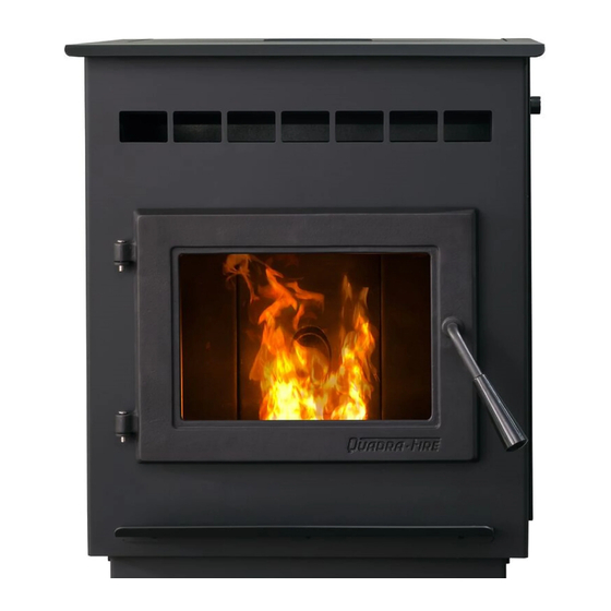
PELLET BURNING APPLIANCE
MODEL NUMBER:
OUTFITTER-I
Tested and approved for wood pellets, Burning of any
other type of fuel voids your warranty.
Installation and service of this appliance should be performed by
qualified personnel. Hearth & Home Technologies recommends
HHT Factory Trained or NFI certified professionals.
1
Installation Manual
Installation & Appliance Set-Up
NOTICE: DO NOT DISCARD THIS MANUAL
CAUTION
R
If the information in these instructions is
not followed exactly, a fire could result
causing property damage, personal injury,
or death.
• Do not store or use gasoline or other flammable vapors
and liquids in the vicinity of this or any other appliance.
• Do not over fire - If appliance or chimney connector
glows, you are over firing. Over firing will void
your warranty.
• Comply with all minimum clearances to combustibles
as specified.
Failure to comply may cause house fire.
Hot glass will cause burns.
• Do not touch glass until it is cooled
• NEVER allow children to touch glass
• Keep children away
• CAREFULLY SUPERVISE children in same room
as fireplace.
• Alert
children
high temperatures
• High temperatures may ignite clothing or other
flammable materials.
• Keep
clothing,
flammable materials away.
Check building codes prior to installation.
• Installation MUST comply with local, regional, state
and national codes and regulations.
• Consult local building, fire officials or authorities
having jurisdiction about restrictions, installation
inspection, and permits.
NOTE: To obtain a French translation of this manual,
please contact your dealer or visit www.quadrafire.com.
REMARQUE : Pour obtenir une traduction française de
ce manuel, s'il vous plaît contacter votre revendeur ou
visitez www.quadrafire.com.
8106-803B
WARNING
WARNING
HOT SURFACES!
Glass and other surfaces are hot
during operation AND cool down.
and
adults
to
furniture,
draperies
CAUTION
hazards
of
and
other
05/22
Advertisement
Table of Contents

Related Manuals for Quadra-Fire OUTFITTER-I

Summary of Contents for Quadra-Fire OUTFITTER-I
- Page 1 PELLET BURNING APPLIANCE or death. • Do not store or use gasoline or other flammable vapors MODEL NUMBER: and liquids in the vicinity of this or any other appliance. OUTFITTER-I • Do not over fire - If appliance or chimney connector glows, you are over firing. Over firing will void your warranty. • Comply with all minimum clearances to combustibles as specified.
-
Page 2: Table Of Contents
G. Equivalent Feet of Pipe ..... . . 14 H. Pipe Selection Chart ......14 Quadra-Fire is a registered trademark of Hearth & Home Technologies. 8106-803B... -
Page 3: Important Safety Information
*** A range of BTU outputs calculated using HHV efficiency and the burn rates from the EPA tests. **** Based on the maximum feed rate per hour multiplied The Outfitter-I is Certified to comply with by approximately 8600 BTU’s which is the average BTU’s 2020 particulate emission standards. from a pound of pellets. This pellet appliance needs periodic inspection and repair for proper operation. -
Page 4: Glass Specifications
D. Glass Specifications J. Stove Composition This appliance is equipped with 5mm ceramic glass. These pellet burning stoves are made of steel, cast iron or Replace glass only with 5mm ceramic glass. Please contact a combination of both with a ceramic viewing glass. These your dealer for replacement glass. stoves incorporate a self-feeding system including a fuel storage hopper and a mechanical feed system which is E. -
Page 5: Getting Started
Getting Started A. Design, Installation & Location Considerations Since pellet exhaust can contain ash, soot or sparks, you must consider the location of: 1. Appliance Location • Windows • Air Intakes NOTICE: Check building codes prior to installation. • Air Conditioner • Installation MUST comply with local, regional, state and • Overhang, soffits, porch roofs, adjacent walls national codes and regulations. -
Page 6: Thermostat Wall Control Location
B. Thermostat Wall Control Location WARNING The thermostat wall control’s location will have some affect on the appliance’s operation. • If you need to run more than 25’ make sure you use a Hearth & Home Technologies disclaims any continuous strand of 18 to 22 gauge thermostat wire. responsibility for, and the warranty will be • When located close to the appliance, it may require a voided by, the following actions: slightly higher temperature setting to keep the rest of the house comfortable. -
Page 7: Install Checklist
F. Install Checklist ATTENTION INSTALLER: Follow this Standard Work Checklist This standard work checklist is to be used by the installer in conjunction with, not instead of, the instructions contained in this installation manual. __________________________________________________________________________ Customer: ______________________________________________________________________ Date Installed: _______________________________________________________________________ Lot/Address: ________________________________________________________________ Location of Appliance:... -
Page 8: Dimensions And Clearances
Dimensions and Clearances A. Appliance Dimensions 21-3/4” (552mm) 3-1/2” (89mm) 11-3/8” 7-7/8” (289mm) (200mm) 33-3/4” (858mm) Figure 8.1 - Top View Figure 8.3 - Front View 22-1/8” (562mm) 12-7/8” (326mm) Figure 8.2 - Side View 8106-803B 05/22... -
Page 9: Clearances To Combustibles (Ul And Ulc)
B. Clearances to Combustibles (UL and ULC) NOTE: • Illustrations reflect typical installations and are FOR DESIGN PURPOSES ONLY. • Illustrations/diagrams are not drawn to scale. • Actual installation may vary due to individual design preference. C. Hearth Pad Requirements (UL and ULC) EMBER PROTECTION: It is necessary to install a Type I floor protector. Floor protector must be non-combustible material, extending beneath appliance with a minimum of 6 inches (152mm) in front of glass and 6 inches (152mm) to both sides of the... - Page 10 25” (635mm) 34-1/2” 3” 2” (876mm) (76mm) (51mm) (from side of appliance) 28-7/8” 42” (733mm) (1067mm) 6” (152mm) 13-5/8” 24-7/8” (from front of appliance) (632mm) (346mm) Figure 10.1 13-58” (346mm) 635mm Figure 10.3 51mm (from side of appliance) 76mm 876mm 733mm 1067mm 152mm...
-
Page 11: Vent Information
Vent Information A. Venting Termination Minimum Requirements Electrical Service Inside Corner FIXED FIXED OPEN CLOSED CLOSED OPEN J or K Termination Cap Air Supply Inlet Gas Meter Restricted Area All minimum clearances are listed with an Outside Air Kit (OAK) installed, unless otherwise noted in table below. Above Finish Grade (the grade surface 24 in. -
Page 12: Avoiding Smoke And Odors
B. Avoiding Smoke and Odors Vent Configurations When installing a pellet appliance with a horizontal vent Negative Pressure, Shut-Down Electrical configuration the frequency of power outages should Power Failure be considered: To reduce the probability of back-drafting or burn-back • Power outages during operation will cause the appliance in the pellet appliance during power failure or shut down to immediately turn off and may create conditions where conditions, it must be able to draft naturally without exhaust... -
Page 13: Negative Pressure
- Recessed lighting the 3 inch (76mm) vertical Top Vent Adapter Kit or the 3 - Attic hatch to 6 inch (76-152mm) Top Vent Offset Adapter, use Listed - Duct leaks double wall flue connector. A Quadra-Fire Outside Air Kit To minimize the effects of negative air pressure: must be used with manufactured home installations. • Install the outside air kit with the intake facing prevailing 3. Residential: The 3 inch (76mm) vertical Top Vent winds during the heating season... -
Page 14: Equivalent Feet Of Pipe
G. Equivalent Feet of Pipe CAUTION The table below can help you calculate the equivalent feet of pipe which is a method used to determine pellet vent Vent surfaces get HOT, can cause burns size (Figure 14.1). if touched. Non-combustible shielding or guards may be required. -
Page 15: Venting Systems
Venting Systems A. Through The Wall NOTE: In Canada, where passage through a wall or partition of combustible construction is desired, the Horizontal termination cap must be a minimum of 6 installation shall conform to CAN/CSA-B365 inches. (152mm) from the wall. Approved for mobile home installations. Must use 3 or 4 inch (76-102mm) “L” or “PL” listed pellet venting or Listed double wall pipe and an CAUTION authorized Outside Air Kit in mobile homes. -
Page 16: Vertical - Interior - Typical Installation
B. Vertical - Interior - Typical Installation D. Vertical into Existing Class A Chimney PREFERRED METHOD #1 Rain Cap Rain Cap Flashing 12 in. 12 in. (305mm) Minimum Flashing (305mm) Minimum Firestop Firestop 6 in. (152mm) Class A Chimney Connector Adapter Ceiling Support Follow vent manufacturer’s... -
Page 17: Masonry
E. Masonry Fireclay flue Concrete Cap Liner with Airspace Flashing 1 in. (25mm) Clearance with Firestop 1 in. (25mm) Clearance 3 in. (76mm) Minimum 6 in. (152mm) Minimum Sheathing Clean-Out Airtight Clean-Out Door Non-combustible Hearth Pad F. Alternate Masonry Fireclay Flue Liner with Airspace Concrete Cap Flashing... -
Page 18: Through The Wall
G. Through The Wall NOTE: In Canada, where passage through a wall or Horizontal termination cap must be a minimum of 6 partition of combustible construction is desired, the installation shall conform to CAN/CSA-B365 inches. (152mm) from the wall. Approved for mobile home installations. Must use 3 or 4 inch (76-102mm) “L” or “PL” listed pellet venting or Listed double wall pipe and an WARNING authorized Outside Air Kit in mobile homes. -
Page 19: Appliance Set-Up
Appliance Set-Up A. Outside Air Kit 1. Measure distance from floor to air vent opening in appliance and mark location on wall. Kit 811-0872 uses a 2 inch flex hose (which is included in 2. Use a saw to cut opening in wall: the kit) and uses hose clamps to secure the hose. - Cut a 2-1/2 to 3 inch opening on inside wall and a 3 to Parts Included in 2 inch Kit 811-0872: 3-1/2 inch opening on outside of house. -
Page 20: Thermostat Installation And Operation
B. Thermostat Installation and Operation There is a 4 screw terminal block located on the back lower left corner of the appliance directly above the power cord The kit comes with a programmable wall thermostat and inlet. The center 2 screws are for the thermostat wires. 25’ of thermostat wire. If you need to run more than 25’... -
Page 21: Mobile Home Installation
Mobile Home Installation You must use a Quadra-Fire Outside Air Kit for CAUTION installation in a mobile home. 1. An outside air inlet must be provided for the combustion THE STRUCTURAL INTEGRITY OF THE MOBILE air and must remain clear of leaves, debris, ice and/or HOME FLOOR, WALL AND CEILING/ROOF MUST snow. It must be unrestricted while the appliance is in... -
Page 22: Reference Materials
Reference Materials A. Service & Maintenance Log Date of Service Performed By Description of Service 8106-803B 05/22... - Page 23 Hearth & Home Technologies 352 Mountain House Road Halifax, PA 17032 Division of HNI INDUSTRIES Please contact your Quadra-Fire dealer with any questions or concerns. For the number of your nearest Quadra-Fire dealer log onto www.quadrafi re.com CAUTION DO NOT DISCARD THIS MANUAL •...