Advertisement
Quick Links
Electronic Seven Day Time Switch
With Photo Sensor Enable And Battery Powered Carryover
OWNER/ INSTALLER INSTRUCTION MANUAL
ATTENTION: READ CAREFULLY BEFORE ATTEMPTING TO INSTALL YOUR INTERMATIC
TIMER! FAILURE TO COMPLY WITH INSTRUCTIONS COULD RESULT IN PERSONAL INJURY
AND/OR PROPERTY DAMAGE! RETAIN FOR FUTURE REFERENCE.
FULL ONE YEAR WARRANTY
If within one (1) year from the date of purchase, this product fails due to
a defect in material or workmanship, Intermatic Incorporated will replace
or repair it free of charge.
The warranty does not apply to: (a) damage caused by accident, abuse,
mishandling, dropping; (b) units which have been subject to unauthorized
repair, opened, taken apart; (c)) units not used in accordance with direc-
tions; (d) damage exceeding the cost of the product. Some states do not
allow a limitation of damages, so the foregoing limitation may not apply to
you. This warranty gives you specific legal rights and you may also have
other rights which vary from state to state.
This warranty service is available by either (a) returning the product to the
dealer from whom the unit was purchased, or (b) mailing postage prepaid
to the authorized service station listed. Please be sure to wrap the prod-
uct securely when mailing to avoid damage. This warranty is made by
Intermatic Incorporated, Intermatic Plaza, Spring Grove, Illinois
60081-9698.
AUTHORIZED SERVICE STATION: INTERMATIC INCORPORATED,
INTERMATIC PLAZA, SPRING GROVE, IL 60081-9698.
®
-1-
ET716CK
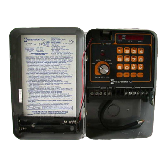
Description
The Intermatic Model ET716CK is an Electronic
Seven Day TIme Switch with Photo Sensor Enable.
Loads can be automatically switched ON or OFF
according to a programmed schedule, providing
appropriate light levels exist. The Photo Enable func-
tion ensures that loads are ON only if the ambient light
level is low enough to require lighting and only if the
user programmed schedule is switched ON. This timer
is not designed to directly switch loads over 5 amps or
tungsten (lamp) or other high inrush loads. The pro-
gram will allow up to 28 set points (14 ON/ 14 OFF)
with up to 196 set points by using repeat daily cycling
for a seven day schedule. The photo sensor assembly
includes a sliding bracket which can be adjusted to
partially shield the photo cell, thereby increasing the
light level at which the load will switch ON and OFF.
The photo sensor can be located up to 1,000 feet from
the electronic time switch using ordinary 18 AWG bell
wire.
CAUTION: Connections made to the photo sensor
inputs, must be made outside of the enclosure and
made using UL listed 14 to 18 AWG wire. DO NOT
apply power to the photo sensor inputs.
Time Switch Specifications
CLOCK VOLTAGE: 120, 240, 277 volt A.C. 60 Hz.
POWER CONSUMPTION: 3.5 Watts Max.
CONTACT RATING: 5 Amps. Resistive @ 24-277
V.A.C. DPDT Isolated Contacts.
SET POINTS: ("On" or "Off"): 28 Total
BATTERY POWERED CARRYOVER: 24 hours.
MIN: "ON" or "OFF" TIME: 1 Minute
MAX. "ON" or "OFF" TIME: 6 Days 23 hours 59
minutes.
SHIPPING WEIGHT: 2.9 Lbs. (1.32 Kg)
CASE: Drawn steel,; 7 3/4" (19.7 cm) high, 5"
(12.7cm) wide, 3" (7.6 cm) deep; gray finish w/lock-
able spring hasp.
KNOCKOUTS: Combination 1/2-3/4" (one on back
and each side, two on bottom)
Photo Sensor
Consists of photo cell light sensor. DO NOT apply
power to this sensor. Use only the supplied photo
sensor with the ET716CK time switch.
HOUSING: Completely sonic welded Lexan case.
WIRING: 2-12" Wire leads provided; additional low
voltage wiring for remote installations is required.
PHOTO SENSOR ACTIVATION: 2 to 15 FC "ON" and
2 to 15 FC "OFF" without the use of the sliding brack-
et. A built in hysteresis of 10% minimum ensures that
the ON and OFF switching levels are not the same.
REPLACEMENT PHOTO CONTROL ONLY: Order
Intermatic part #177ET144A
General Safety Information
WARNING: Disconnect all power before installing or
servicing this timer or its connected loads.
1. Follow all local electrical and safety codes, as well
as the National Electrical Code (NEC), and the
Occupational Safety and Health Act (OSHA).
2. If the power disconnect point is out of sight, lock it
in the "OFF" position and tag it to prevent unexpected
application of power.
3. This timer must be grounded.
4. Do not exceed the maximum current carrying
capacity of this timer.
5. Always replace the plastic insulator covering the
Advertisement

Related Manuals for Intermatic ET716CK


Summary of Contents for Intermatic ET716CK
-
Page 1: General Safety Information
FULL ONE YEAR WARRANTY If within one (1) year from the date of purchase, this product fails due to a defect in material or workmanship, Intermatic Incorporated will replace or repair it free of charge. The warranty does not apply to: (a) damage caused by accident, abuse, mishandling, dropping;... - Page 2 For inductive loads (lighting contactors, relays, etc.), it is necessary to install a surge suppressor across the time switch contacts. The surge suppressor selected must be of the same voltage as the load (contactor or relay coil) being controlled. Use Intermatic part...
- Page 3 Programming Steps WARNING: DO NOT PRESS RESET BUTTON WHILE PROGRAMMING OR THE ENTIRE PROGRAM WILL BE LOST. SET OR MODIFY THE TIME OF DAY: 1. Turn selector switch to “SET”. 2. Press the numbered button corresponding to the day. For examaple press ´2´...
-
Page 4: Trouble Shooting
277 VOLT 277 VOLT CONTACTOR COIL CONTACTOR COIL PHOTO SENSOR PHOTO SENSOR LOAD LOAD INTERMATIC INCORPORATED SPRING GROVE, ILLINOIS 60081-9698 CORRECTIVE ACTION TIMER POWER TIMER POWER 1 1 2 2 3 3 4 4 5 5 9 9 10 10 11...