Table of Contents
Advertisement
Quick Links
LIGHTING CONTROLS EQUIPMENT
Use this Installation Guide for relay panel hook-up directions.
Use the System Start-Up Guide for system-wide wiring and programming initialization.
READ, FOLLOW AND SAVE THIS INSTRUCTION MANUAL
TABLE OF CONTENTS
Installation Instructions ............................................2
Removing the Chasis ..............................................3
Control of Emergency Loads ...................................3
Line and Low Voltage Connections .........................4
Low Voltage Inputs ..................................................5
INSTALLATION GUIDE
INSTALLER - READ THIS FIRST:
Contact Closure Inputs ............................................5
Panel Overview .......................................................6
Internal Wiring Schematic........................................7
Trouble Shooting .....................................................8
The EM1400 series is a programmable relay panel
with 8 or 16 relays. A master panel can stand alone
or can control up to 16 digital devices: photocell
cards, digital switches, contact closure input cards
(DigiLinks), slave Blue Box panels or other digital
devices.
•
8 or 16 normally closed latching relays
•
14 optional programmable contact closure inputs
can control any relay(s) in any panel(s)
•
On-board manual override for each relay
•
32 individual 365 day astronomical and time-of-
day schedules can control any relay(s)
•
Clock schedules can be overridden by digital
switches through simple programming steps
INTERMATIC INCORPORATED
SPRING GROVE, IL 60081-9698
http://www.intermatic.com
EM1400 SERIES
INSTALLATION
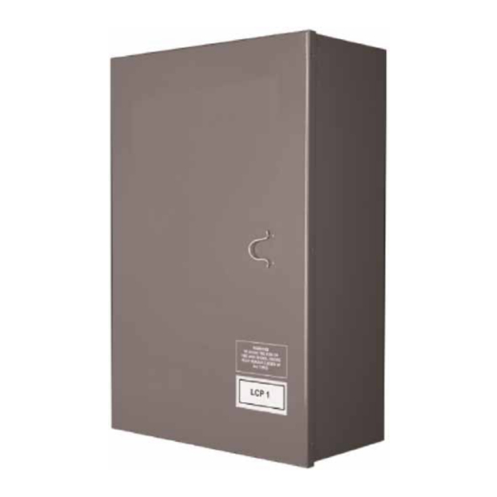
MANUAL
Advertisement
Table of Contents

Summary of Contents for Intermatic EM1400 SERIES
-
Page 1: Table Of Contents
Panel Overview ...6 Internal Wiring Schematic...7 Trouble Shooting ...8 The EM1400 series is a programmable relay panel with 8 or 16 relays. A master panel can stand alone or can control up to 16 digital devices: photocell cards, digital switches, contact closure input cards (DigiLinks), slave Blue Box panels or other digital devices. -
Page 2: Installation Instructions
Power supply should be supplied from a dedicated breaker. Land 120v or 277v on appropriate lugs and Neutral and Ground as indicated. EM1400 Series Installation Guide Do not power-up the panel electronics until the bus has been activated (see the Quick Start Guide). -
Page 3: Removing The Chasis
Normal Power Distribution Panel Emergency Power Distribution Panel The EM1400 series is listed for controlling emergency circuits (ETL Listed to UL 924), but may not control both normal and emergency loads in the same enclosure. When controlling emergency loads, use normal power... -
Page 4: Line And Low Voltage Connections
Pg. 4 Overview - Line & Low Voltage Connections The EM1400 digital bus allows up to 16 digital devices (not including photo- cells, or contact closures devices), and may be up to 4000 ft. in length. Refer to the System Planning Guide in your support CD when planning long bus lengths (over 500 ft.). -
Page 5: Low Voltage Inputs
Intermatic © Low Voltage Inputs Any EM1400 series relay panel may be used with “digital” switches that sit on the data bus and are connected with Cat. 5 cable with RJ45 connectors. Additionally, one may order the EM1400 with the op- tional contact closure inputs. -
Page 6: Panel Overview
(120v and 277v) in accordance with the NEC and local code requirements. Electronics Backplate High voltage - low voltage barrier High Voltage Backplate EM1400 Series Installation Guide Programming Buttons(in Master Panel only): Scroll and tab to access control features for the system... -
Page 7: Internal Wiring Schematic
Intermatic © Internal Wiring Schematic Internal jumpers and cables for the EM1400 series are shown below. All jumpers and internal wiring con- nections use depluggable connectors. Gently tug a connector after connecting to ensure a firm fit and then visually inspect that the connector is seated squarely. -
Page 8: Trouble Shooting
INTERMATIC INCORPORATED, SPRING GROVE, IL 60081-9698 To initiate an override (re-start the timer) from the control card, press the relay button once. Or use an override switch.


