Table of Contents
Advertisement
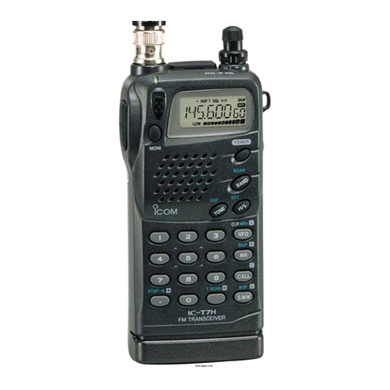
INSTRUCTION MANUAL
DUAL BAND FM TRANSCEIVER
iT7H
This device complies with Part 15 of the FCC rules. Operation is sub-
ject to the following two conditions: (1) This device may not cause
harmful interference, and (2) this device must accept any interference
received, including interference that may cause undesired operation.
Advertisement
Table of Contents

Related Manuals for Icom IC-T7H


Summary of Contents for Icom IC-T7H
- Page 1 INSTRUCTION MANUAL DUAL BAND FM TRANSCEIVER iT7H This device complies with Part 15 of the FCC rules. Operation is sub- ject to the following two conditions: (1) This device may not cause harmful interference, and (2) this device must accept any interference received, including interference that may cause undesired operation.
-
Page 2: Important
IMPORTANT READ ALL INSTRUCTIONS carefully and completely before using the transceiver. SAVE THIS INSTRUCTION MANUAL—This instruction man- ual contains important operating instructions for the IC-T7H. EXPLICIT DEFINITIONS The explicit definitions below apply to this instruction manual. WORD Personal injury, fire hazard or electric shock RWARNING may occur. -
Page 3: Unpacking
For U.S.A. only CAUTION: Changes or modifications to this device, not ex- pressly approved by Icom Inc., could void your authority to operate this device under FCC regulations. UNPACKING Accessories included with the transceiver: Antenna ...1 Handstrap ...1... -
Page 4: Table Of Contents
TABLE OF CONTENTS IMPORTANT ... i EXPLICIT DEFINITIONS ... i CAUTIONS ... i UNPACKING ... ii TABLE OF CONTENTS ... iii 1 PANEL DESCRIPTION ... 1 – 5 Switches, controls, keys and connectors ... 1 Function display ... 5 2 BATTERY PACKS AND ACCESSORIES ... 6 – 9 Battery pack charging ... -
Page 5: Panel Description
Switches, controls, keys and connectors [SP/MIC] [LOCK] [PTT] [BAND] [H/L] [TONE] PANEL DESCRIPTION [DIAL] [VOL] [RX/TX] [MONI] [POWER] [DC13.5V] LOCK MONI POWER SCAN CLR MHz SKIP CALL DTMF•M T SCAN S.MW... - Page 6 PANEL DESCRIPTION PTT SWITCH [PTT] (p. 12) Push and hold to transmit; release to receive. LOCK SWITCH [LOCK] Slide up to turn the lock function ON. • [PTT], [VOL], [H/L], [MONI] and [POWER] function even when the lock function is activated. ANTENNA CONNECTOR (p.
- Page 7 !1 OUTPUT POWER SWITCH [H/L(SET)] Push to toggle between low and high output power (p. 12). • “LOW” appears when low output power is selected. Push and hold to enter set mode. !2 TONE SWITCH [TONE(DUP)] Push this switch to activate the following func- tions in order (pgs.
- Page 8 PANEL DESCRIPTION !7 TONE SCAN KEY [TSCAN?] Push this key for 1 sec. to start and stop tone de- T SCAN code scan (p. 13). • When a subaudible tone is detected, the tone fre- quency is displayed and overwrites the prepro- grammed: tone squelch frequency when the tone squelch is in use;...
-
Page 9: Panel Description ............................................ 1
Function display DUPLEX INDICATORS (p. 13) Appear during semi-duplex operation. • “– DUP” appears for minus duplex; “DUP” only appears for plus duplex. TONE INDICATORS (p. 21) “T” appears when the subaudible tone encoder is in use, “T SQLS” appears during pocket beep operation and “T SQL”... -
Page 10: Battery Packs And Accessories
BATTERY PACKS AND ACCESSORIES Battery pack charging The supplied* BP-180 BATTERY PACK Ni-Cd batteries and can be charged approx. 300 times. Charge the battery pack before first operating the transceiver or when the battery pack becomes exhausted. *Optional for versions which come with the BP-170 If you want to be able to charge the battery pack more than 300 times, the following points should be observed: 1. -
Page 11: Charging Connections
Charging connections D Regular charging Attach the supplied* or optional battery pack; then, connect the supplied* wall charger via an AC outlet as shown below. *Optional for versions which include a battery case. To [DC13.5V] Charging periods: 15 hours (w/BP-171, BP-173 or BP-180) 20 hours (w/BP-172) BATTERY PACKS AND ACCESSORIES D Rapid charging with the BC-119... -
Page 12: Battery Case
BATTERY PACKS AND ACCESSORIES D Operation with an optional cable Connect an optional charger or cable to the transceiver as il- lustrated below. Be careful of battery overcharging as the con- nected battery is charged simultaneously. CAUTION: Remove dry cell batteries when the BP-170 is connected, otherwise the battery may BATTERY CASE leak and damage the transceiver. -
Page 13: Battery Packs And Accessories ................ 6
Accessory attachment D Antenna Insert the supplied antenna into the an- tenna connector and rotate the antenna as shown in the diagram below. Keep the jack cover attached when jacks are not in use to avoid bad con- tacts. CAUTION: Transmitting without the antenna may... -
Page 14: Basic Operation
BASIC OPERATION Power ON Push and hold [POWER] for 1 sec. to turn power • Current battery voltage is displayed for 2 sec. POWER for 1 sec. • The display shows the approx. volt- age in 0.5 V steps. • When the battery voltage is lower than 4.5 V, “LOW V”... -
Page 15: Setting Tuning Steps
D Via the keypad (other band directly) Push [VFO] to select VFO mode. Push 6 digit keys, starting from the 100 MHz digit. • The operating band changes automatically. • It’s not necessary to input the decimal point. D Other methods VIA THE DIAL: Rotate [DIAL] to change the frequency ac- cording to the set tuning steps. -
Page 16: Selecting A Memory Channel
BASIC OPERATION Selecting a memory channel Push [MR] to select memory mode. Push 2 digit keys to select the desired memory channel (or rotate [DIAL]). • The first nine memory chan- nels are preceded by a “0.” • To select scan edges 1A to 4B, use [ ] for “A”... -
Page 17: Repeater Operation
Repeater operation D General When using a repeater, the transmit frequency is shifted from the receive frequency by the offset frequency. It is convenient to program repeater information into memory channels (p. 15). Set the operating band and receive frequency (repeater output frequency). - Page 18 Auto low power When transmitting for 6 continuous min. at high power, the IC-T7H automatically selects low power. This function cannot be turned OFF and activates when the power supply is at ap- prox. 11 V or more. To return to high power on transmit, select receive, then switch back to transmit.
-
Page 19: Advanced Functions
Memory/call channels The transceiver has 70 memory channels (60 regular, 4 pairs of scan edge channels for mixed bands and 1 call channel for each band). Note that memory channels are not grouped ac- cording to band. In other words, a given memory channel can be programmed with either a VHF frequency or a UHF fre- quency. -
Page 20: Programming After Selection
ADVANCED FUNCTIONS D Programming after selection Select the memory channel to be programmed: Push [MR] to select memory mode. Rotate [DIAL] (or use the keypad) to select the memory channel. • Non-programmed channels cannot be selected. Set the desired frequency in VFO mode: Push [VFO] to select VFO mode. -
Page 21: Dtmf Memory Operation
DTMF memory operation D Programming a DTMF code The transceiver has 9 DTMF memory channels (D1 to D9) for storage of often-used DTMF codes of up to 16 digits. Push [ DTMF] for 1 sec. to enter • DTMF memory mode. Rotate [DIAL] to select the desired channel. -
Page 22: Scan Operation
ADVANCED FUNCTIONS Scan operation D Full/programmed scan FULL SCAN Band edge (e.g. 144.00) Scan Jump PROGRAMMED SCAN Band Scan edges edge Scan Jump FULL SCAN: Repeatedly scans all frequencies over an entire band (the 144 MHz band or the 430(440) MHz band). PROGRAMMED SCAN: Repeatedly scans between two user-programmed frequencies. - Page 23 D Memory (skip) scan ALL CHANNEL SCAN Not yet programmed Mch 2 Mch 3 Mch 4 Mch 5 Mch 1 Mch 60 Mch 11 Mch 10 Mch 9 BAND SELECT SCAN (Example: 144 MHz band) Not yet programmed Mch 2 Mch 3 Mch 4 Mch 5...
- Page 24 ADVANCED FUNCTIONS D Setting a skip channel Memory channels can be set to be skipped during memory scan. This is useful to speedup the memory scan interval. Select the memory channel to be programmed as a skip channel: Push [MR] to select memory mode. Rotate [DIAL] (or use the keypad) to select a memory channel.
-
Page 25: Subaudible Tone Operation
Subaudible tone operation D Tone squelch operation The tone squelch opens only when receiving a signal con- taining a matching subaudible tone. You can silently wait for calls from group members using the same tone. Set the operating frequency. Set the desired subaudible tone in set mode. •... -
Page 26: Pocket Beep Operation
ADVANCED FUNCTIONS D Pocket beep operation This function uses subaudible tones for calling and can be used as a “common pager” to inform you that someone has called while you were away from the transceiver. Set the operating frequency. Set the desired subaudible tone (same as that used for tone squelch operation, “CT”) in set mode. -
Page 27: Other Functions
Initial set mode Initial set mode is accessed at power ON and allows you to set seldom-changed settings. In this way you can “customize” transceiver operation to suit your preferences and operating style. D Entering initial set mode While pushing [ SET] push [POWER] to turn power (H/L) •... - Page 28 OTHER FUNCTIONS D Auto power OFF This item allows you to set a time at which the transceiver will automati- cally turn OFF. The power OFF time can be set to 20, 40, 60 min. or turned OFF. D Function display backlighting When set to AUTO, display backlight- ing automatically turns on when a key is pushed;...
-
Page 29: Dtmf Speed
D Power saver duty cycle This item sets the power saver duty cycle — the ratio of receive circuit ON to receive circuit OFF while standing by. The duty cycle can be set to AUTO, 1:4 or OFF. Setting to AUTO conserves the most battery power. -
Page 30: Channel Indication Mode
OTHER FUNCTIONS Channel indication mode Channel indication mode is used to simplify operation. In this mode only pre-programmed memory channel numbers are displayed and functions are limited ([POWER], [LOCK], [PTT], [MONI], [H/L], [SCAN] and the tuning dial are functional). While pushing [MR], push [POWER] to turn power ON. •... -
Page 31: Troubleshooting
If your transceiver seems to be malfunctioning, please check the following points before sending it to a service center. PROBLEM No power comes on. • The battery is exhausted. (A slight current flows in the circuits even when the power is OFF.) •... -
Page 32: Options
MB-30 MOUNTING BRACKET For mounting the transceiver on the inside door panel of a vehicle or on a wall. LC-136/LC-137 CARRYING CASES LC-136: for IC-T7H with BP-170/171/172. LC-137: for IC-T7H with BP-173/180. SP-13 EARPHONE Provides clear receive audio in noisy environments. -
Page 33: Specifications
Tx: 144–148 U.S.A. Rx: 118–174* Frequency Europe, U.K. 144–146 coverage (MHz) Tx: 144–148 Asia Rx: 118–174* Tx: 144–148 Italy Rx: 136–174* Guaranteed ranges are: 144–148 440–450 430–440 Mode FM (F3E) ±5 ppm Frequency stability (0°C to +50°C; +32°F to +122°F) Tuning steps (kHz) 5, 10, 12.5, 15, 20, 25, 30 or 50 Antenna connector... -
Page 34: Mode Arrangement
MODE ARRANGEMENT VFO MODE CALL CALL MODE SKIP POWER AT POWER ON NOTE: Displays for set and initial set modes show the de- fault settings—rotate [DIAL] to change the condition. MEMORY MODE CALL CHANNEL INDICATION MODE See p. 26 for details push for 1 sec. - Page 35 CTCSS tones (p. 21) CLR MHz POWER TO ENTER at power ON Auto power OFF (p. 24) MIC simple mode (p. 23) LCD contrast (p. 25) SET MODE Repeater tones (p. 14) T SQL Scan resume condition (p. 20) *Cannot be selected when entering set mode from a memory or call channel. INITIAL SET MODE LCD backlight (p.
- Page 36 A-5551S-1EX Printed in Japan 6-9-16 Kamihigashi, Hirano-ku, Osaka 547-0002 Japan © 1998 Icom Inc.